Key Facts
- •
MRI has superior contrast resolution to CT.
- •
CT, unlike MRI, can directly image trabecular and cortical bone.
- •
Computed tomography (CT) has greater spatial resolution than magnetic resonance imaging (MRI), so very small structures can be examined with excellent detail.
- •
Multidetector CT (MDCT) scanners are fast, producing image data sets of a body part in seconds.
- •
Isotropic imaging, in which all dimensions of the volume elements of the image are equal in size, allows production of high-resolution images in any plane after the initial source images are obtained.
- •
Intraarticular contrast injection (arthroCT) can evaluate internal derangement and is particularly useful in patients who cannot undergo MRI examination or have undergone joint surgery (e.g., articular cartilage or meniscal surgery).
- •
The radiation dose from MDCT can be relatively high.
- •
Three-dimensional displays may be helpful especially for analyzing complex fractures and lessening artifact accompanying orthopedic hardware.
Recent advances in multidetector computed tomography (MDCT) greatly affect musculoskeletal imaging . Current MDCT systems have unsurpassed spatial resolution, are capable of scanning through metal, and are lightning-fast. These attributes make the modality ideally suited for, among other things, assessing bone surfaces, the integrity of orthopedic hardware, and trauma patients. When used in combination with arthrography, MDCT is often preferable to magnetic resonance imaging (MRI) for evaluating internal derangement, especially in the postoperative setting. The essential features of these new systems that allow such imaging are the new detector arrays, improved software, and variable scan speed. This chapter will briefly address some of the technical aspects of MDCT and illustrate how this new technology contributes to patient care. MDCT radiation dose issues will be addressed as well.
MDCT TECHNOLOGY
All computed tomography (CT) relies on a photon beam passing through a patient and being detected after the passage by a detector; hence the circular, or doughnut, shape of CT systems. If the photon beam passes through dense material, such as bone, the detector senses a faint signal. Conversely, if the beam passes through mostly air, such as in the lungs, the detector senses a strong signal. After a scan is complete, a computer sorts out the various signals, or attenuation values, and constructs an image. Prior to MDCT, CT systems generated a single beam, which passed through the patient and was sensed by a single detector. Current MDCT systems generate multiple photon beams simultaneously that are sensed by broad detector arrays. Thus many slices may be obtained at once.
Current MDCT systems generate multiple photon beams simultaneously that are sensed by broad detector arrays. Thus many slices may be obtained at once.
In addition, the new detector arrays may be adjusted, or collimated, to select a greater variety of slice thicknesses. Another feature of MDCT systems that warrants mention is the table that the patient lies on. The speed of this table may be varied. For trauma imaging of an uncooperative patient, a fast table speed is desirable to minimize patient motion. Sometimes, such as when scanning through orthopedic hardware, a slow table speed is desired to scan through metal. These features of MDCT make the systems extremely versatile.
Current MDCT systems typically have matrix sizes of 512 × 512 or 1024 × 1024. The higher the matrix is, the greater the spatial resolution. For example, a scan with a field of view of 30 cm and a 512 × 512 matrix is made of a grid with squares that are less than 0.06 cm on each side. This defines the resolution in two planes, height (anteroposterior) and width (mediolateral). The resolution in the third plane (depth) is defined by the slice thickness. Current MDCT scanners produce slices as thin as 0.5 or 0.6 mm. The result is that MDCT systems can collect data in true cubes. More precisely, MDCT scanners can produce isometric data sets that have the same dimensions in all three planes. In turn, isometric data sets allow reformatted images to be produced in any plane without image degradation. Hence two-dimensional (2D) multiplanar reformatted (MPR) images look as though they were acquired directly and three-dimensional (3D) images have exquisite detail. Current software allows quick and easy data manipulation to produce reformatted images in any plane and angle.
The production of isometric data sets (identical length, width, and depth image information) allows images to be reformatted in any plane without image degradation and the production of exquisite 3D images.
To produce robust image data sets, overlapped slices are obtained during scanning. For example, a wrist scan, which requires high detail, will be obtained, using 0.6-mm slices at 0.2-mm or 0.3-mm intervals. Such scan overlap acquires data sets that produce seamless reformatted images. Another consequence of overlapping slices is increased mAs, or simply the number of photons that pass through a body part.
Overlapping slices, useful when imaging small structures, increase the number of photons that pass through a body part and therefore increase the radiation dose.
Large orthopedic devices can be scanned through using thick slices with 50% to 60% slice overlap. For example, a total hip prosthesis can be scanned through to evaluate for loosening. Such a scan might use 3-mm slices with 2-mm overlap and generate more than 500 mAs. Fortunately, new MDCT systems are increasingly efficient and reduce radiation dose to the patient. In addition, such a scan should be performed only in an older patient.
Many parameters can be manipulated in current MDCT systems. The result is an extremely versatile technology that can scan small body parts with high resolution as well as large body parts that may contain large orthopedic devices. If proper scanning technique is used, MPR or 3D images may be obtained in all cases. Examples of this technology’s clinical versatility and utility are presented below.
HOUNSFIELD UNITS
As noted earlier, computers generate MDCT images from the differing attenuation values of tissues. These attenuation values are measured in Hounsfield units. Dense tissues, like bone, have high Hounsfield unit values. Air, which has relatively low density, has an extremely low Hounsfield unit value. Tissues such as fat and muscle have intermediate values and vary according to their density ( Table 1-1 ; see Glossary). Cortical bone typically has values of 400 to 1000, while traebecular bone has values of 100 to 300. By contrast, air measures -400 to -600. An intermediate tissue like muscle typically has values of 40 to 80. Fat, which is less dense then muscle, has values of -60 to -100. Simple fluid, such as may be found in a simple renal cyst or uncomplicated joint effusion, has a density between muscle and fat. Accordingly, fluid has Hounsfield values of 10 to 20 or 30.
The Hounsfield values for blood vary depending on the age and location of the blood. Extravascular blood from an acute bleed typically will have values of 50 to 90. As a hematoma forms, portions of the clot may liquefy and have Hounsfield values that approach fluid (20 to 30). However, some portions may contain hemosiderin or dystrophic calcification and have Hounsfield values in the 90s or low 100s. Intravascular blood typically has Hounsfield values around 90, unless the patient has been given intravenous contrast. Many factors influence the Hounsfield value of contrast-enhanced blood, including the timing of the image acquisition relative to the injection and whether the blood is venous or arterial. In general, arterial blood has higher Hounsfield values (low to mid or high hundreds) than venous blood (low hundreds).
Assessing Cortical Surfaces
Radiographs are used first in the workup of cortical surfaces; they are an excellent first step and often all that is required. Radiographs can diagnose fractures, dislocations, erosions, osteomyelitis, and a host of other disorders. In addition, radiography is inexpensive and widely available. Unfortunately radiographs suffer limitations and sometimes fail to diagnose the abnormality in question. For example, scaphoid fractures are frequently missed with radiographs. Radiographs also can misdiagnose femoral head collapse in patients with osteonecrosis.
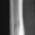
Scaphoid wrist fractures can have poor outcomes if they are not recognized and treated. Fractures of the waist or proximal pole of the bone can disrupt the blood supply and lead to osteonecrosis of the proximal pole. Because the scaphoid has cortical surfaces that run in many planes and at various angles, fractures of the bone may be radiographically occult. In patients with persistent symptoms but negative or equivocal radiographs, MDCT or MRI can be used to diagnose a radiographically occult fracture. Theoretically MRI may be more sensitive than MDCT for detecting occult fractures because of superior contrast resolution that allows edema and hemorrhage and the fracture line to be identified. Currently, however, MDCT has superior spatial resolution and can visualize directly the cortical surfaces. Because the management of scaphoid injury requires visualization of the cortical surfaces and any cortical offset or discontinuity, MDCT is frequently ordered to diagnose radiographically occult fractures. Our hand surgeons reserve MRI for cases where MDCT is negative and concern for fracture persists or if there is concern for soft tissue damage.
Because of its availability and ability to define cortical discontinuity and deformity, MDCT may be the imaging modality of choice for identifying acute, radiographically occult scaphoid fractures.
MDCT scanning for scaphoid fractures uses thin slices with overlap and a high-resolution filter for extreme bone detail. The images are acquired axially or oblique axially, and then MPRs are produced in the coronal and oblique sagittal planes, the latter along the long axis of the scaphoid ( Figures 1-1 and 1-2 ). If necessary, patients can be scanned without removing their casts or splints.


A CT scan can be obtained with the extremity in a cast or splint.
The management of osteonecrosis of the femoral head relies on cortical integrity as well. Some surgeons will consider core decompression or free fibular graft transplant in young patients with stage III disease. However, once the femoral head collapses, those interventions are no longer tenable. Frequently, femoral head collapse is difficult to see with radiography, but MDCT can detect collapse easily. Moderately thick slices with 50% overlap are obtained in the axial orientation. Subsequently, coronal and sagittal MPRs are obtained. Even large patients or patients with prosthetic devices in the contralateral hip can be scanned, although the slice thickness and other parameters may require adjustment to increase mAs ( Figure 1-3 ).


Imaging Patients with Orthopedic Hardware
Patients with orthopedic hardware devices frequently require imaging to evaluate the status of the device as well as the surrounding bone. For example, fixation devices for fractures can fail, and sometimes, even if the fixation device maintains its integrity, nonunion of the fracture can occur. Radiographs are frequently inconclusive, and magnetic resonance (MR) images can become badly degraded in the presence of metal. MDCT easily scans through such devices and can assess bone healing as well as the integrity of the device.
Small fixation devices require relatively high-resolution MDCT scans. Scans to evaluate scaphoid fracture fixation screws, for example, use thin, overlapping slices and high-resolution filters. The wrist is scanned axially or oblique axially, and MPRs are obtained coronally to the wrist and oblique sagittally to the long axis of the scaphoid or the fixation screw. Bony union or nonunion can be determined, and the status of the fixation screw can be assessed as well ( Figures 1-4 and 1-5 ).


Large fixation devices can be scanned as well, but these scans require imaging parameters, such as thicker slices, that produce higher mAs. A relatively low-resolution or soft-tissue filter is used. Again, the image data acquisition is axial, and MPR images are obtained in any desired plane. Because the scans are nearly isotropic and overlapping slices are used, the MPRs can be obliqued in any orientation without significant loss of spatial resolution ( Figure 1-6 ).


The total hip prosthesis presents perhaps the most difficult situation for imaging. These implants are made of dense metal, are thick, have an interface to allow movement, and have a curved geometry. Despite the problems that such devices present, the need for imaging is increasing because the use of these devices increases each year for indications such as end-stage osteoarthritis or inflammatory disorders, osteonecrosis, and trauma. Indications for imaging patients with total hip implants include suspected loosening, infection, particle disease, and fracture.
The nature of total hip prostheses necessitates high-mAs technique for adequate scanning. Relatively thick, overlapped slices are obtained axially with a low-resolution filter. However, with proper MDCT scanning parameters, high-quality source images and MPRs can be obtained, and the numerous causes of pain and failed hip prostheses can be evaluated ( Figures 1-7 and 1-8 ). Because of the high-mAs technique (and therefore high radiation dose), such scanning should be reserved for an appropriate patient population.


Imaging Trauma Patients
Trauma patients present many difficulties for imaging. Injured patients more often than not are in pain. Because of the pain, they may not remain still and may not assume ideal positions for imaging. If they have suffered head trauma, they may not be able to cooperate. In fact, they may be combative. Frequently they are on trauma boards and may have their injured limbs in slings or external fixation devices. These factors may create patient movement and difficulty in positioning body parts.
MDCT is ideally suited to image these patients. As noted previously, the patient table on these systems has a variable speed. By increasing table speed, scans may be acquired more quickly and the effect of patient movement minimized. Likewise, scan time can be shortened by decreasing slice overlap and increasing slice thickness. The effect of increasing table speed and decreasing slice overlap is loss of mAs. The effect of increasing slice thickness is loss of spatial resolution. These trade-offs are manageable and acceptable to obtain a diagnostic scan in a badly hurt or uncooperative patient. Using these strategies, injuries that require immediate attention can be identified.
MDCT deals with the difficulty of positioning trauma patients through the use of isotropic or nearly isotropic imaging. Even if the obliquity used to scan a limb is not ideal, MPRs can be obtained. Because relatively thicker slices with little or no overlap may be used on a trauma patient, the data set may not be isotropic. Nonetheless, MPRs of some sort should be obtainable for initial evaluation. Once the patient is stable, more definitive scans may be obtained if indicated.
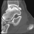
Even with trauma boards, splints, and external fixation devices in place, scans of injured limbs and joints may be obtained with appropriate MDCT technique. These scans are particularly valuable when assessing comminuted fractures around complex joints such as the shoulder, elbow, wrist, knee, and ankle. Spine trauma may be assessed as well. Again, the scanner’s ability to obtain isometric or nearly isometric data sets overcomes problems with patient positioning. The ability to concurrently generate high mAs overcomes the issue of external fixation devices and other orthopaedic hardware ( Figures 1-9 to 1-11 ).


Related posts:

Stay updated, free articles. Join our Telegram channel

Full access? Get Clinical Tree


