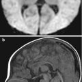
Fig. 2.1
Patient motion artifact. Axial CT image shows blurring of anatomical structures with apparent duplication of the nasal bones, mimicking fractures
Some scanner models use overscan mode for axial body scans, whereby an extra 10 % or so is added to the standard 360° rotation (Barrett and Keat 2004). The repeated projections are averaged, which helps reduce the severity of motion artifacts. The use of partial scan mode can also reduce motion artifacts, but this may be at the expense of poorer resolution. Most scanners, when used in body scan mode, automatically apply reduced weighting to the beginning and end views to suppress their contribution to the final image. However, this may lead to more noise in the vertical direction of the resultant image, depending on the shape of the patient. In addition, specialized motion correction is available on some scanners.
2.2.2 Ring Artifact
Ring or band artifacts are caused by a detector that is out of calibration and are seen in third-generation scanners (Barrett and Keat 2004). This tends to occur with solid-state detectors, as opposed to gas-filled detectors. Ring or band artifacts appear as bright or dark circular bands (Fig. 2.2). Furthermore, the rings can be complete or partial. Although these artifacts are unlikely to lead to a misdiagnosis, they can render the images nondiagnostic when extensive. The problem can be addressed by regular maintenance of calibration and minimizing exposure to temperature drifts.
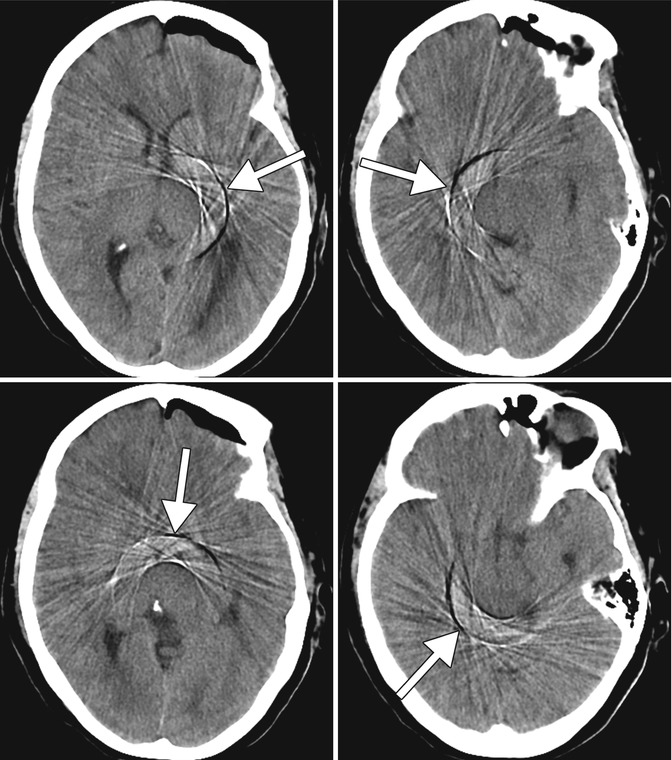
Fig. 2.2
Ring artifact. Sequential axial CT images of the brain show concentric light and dark rings in the middle of the images (arrows)
2.2.3 Beam-Hardening and Metal Streak Artifacts
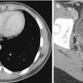
Beam hardening is the process by which the average energy of the polychromatic X-ray beam increases as it passes through an object due to preferential absorption of lower-energy photons (Popilock et al. 2008). This process manifests as a cupping or bloom artifact. Cupping appears as relatively darker toward the center of a rounded object as compared to the periphery, even if the object is uniform in attenuation. Bloom artifact appears as regional dark and bright bands emanating from particularly dense materials, such as bone, calcifications, and iodinated contrast agent. The streaks can obscure adjacent structures and mimic pathology, such as dissection (Fig. 2.3). Metal hardware, particularly stainless steel, can absorb so much of the incident X-rays that there is complete obscuration of the surrounding tissues. This process produces metal streak artifacts, which appear as bands of very low attenuation emanating from the hardware (Fig. 2.4).
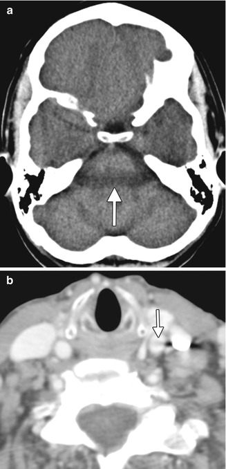
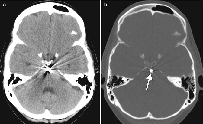
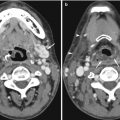
Fig. 2.3
Beam-hardening artifact. (a) Axial CT image of the brain shows a dark band between the petrous bones, which obscures a portion of the brain stem (arrow). (b) Axial CTA image of the neck shows a dark band across the left common carotid artery extending from the densely opacified adjacent internal jugular artery, potentially mimicking a dissection (arrow)
Fig. 2.4
Metal streak artifact. (a) Axial CT image taken in the “brain window” shows extensive bright and dark lines emanating from the coil mass within a basilar artery aneurysm, which obscure the underlying anatomic detail. (b) The artifact is less conspicuous on the corresponding “bone window” CT image. The metallic coil is arrowed
Beam hardening can be reduced through the use of filters that pre-harden the X-ray beam before entering the body. Additional bow-tie filters can be used to preferentially harden the X-ray beam at the edges since these are expected to pass through thinner parts of the body and otherwise undergo less beam hardening in the process compared to the more centrally directed X-rays. Beam-hardening artifact can also be reduced by calibrating the detectors using phantoms of variable sizes and using correction software based on an iterative algorithm. Finally, beam hardening related to intravenous contrast agent can be minimized by the use of saline flushing and caudo-cranial scanning.
2.2.4 Quantum Mottle
Quantum mottle or photon starvation refers to the dose-related image noise related to insufficient X-ray photons reaching the detector (Barrett and Keat 2004). The artifact appears as granular streaks, often in high-attenuation structures, such as those in the shoulder region (Fig. 2.5). Quantum mottle tends to be more pronounced in patients with a large body habitus. Using the appropriate tube current can avoid the effects of photon starvation. A generalized adaptive median filter can be used for noise suppression and edge preservation. Iterative reconstruction techniques are useful for maintaining image quality while minimizing the radiation dose, as described later in this chapter (see Sect. 2.4.2).
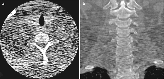
Fig. 2.5
Quantum mottle. (a) Axial and (b) coronal CT images of the cervical spine show poor anatomic definition, particularly at the level of the shoulders, due to large body habitus and photon starvation. In these images, the quantum mottle is accentuated due to poor signal-to-noise ratio
2.2.5 Aliasing
Undersampling due to excessively large intervals between projections can lead to aliasing (Barrett and Keat 2004). This phenomenon tends to occur at sharp edges and with small structures and manifests as fine bands. A particular form of aliasing that can occur with helical CT is the windmill artifact, in which there are multiple radially oriented alternating light and dark bands (Fig. 2.6). The windmill effect is exacerbated by the use of higher pitch. However, this artifact is usually not problematic unless fine detail is desired. The use of high-resolution techniques can minimize aliasing artifacts.
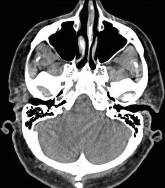
Fig. 2.6
Windmill artifact. Axial helically acquired CT of the brain shows numerous alternating dark and bright lines in a radiating pattern centered upon sharp bony structures
2.3 Misinterpretation Pitfalls
2.3.1 Suboptimal Contrast Bolus Timing
Contrast enhancement in CT is affected by several factors, including patient, contrast agent, and CT scanning. Perhaps the most significant patient-related factor that can affect the magnitude of vascular and parenchymal contrast enhancement is body weight. Typically, either the contrast agent volume and/or concentration is increased as body weight increases. However, increasing these proportionately to weight may be inaccurate. Rather, adjusting for the lean body weight or body surface area may be more appropriate. The timing of contrast enhancement is greatly dependent upon cardiac output and cardiovascular circulation. With lower cardiac output, there is a delayed contrast agent bolus arrival but more prominent peak arterial and parenchymal enhancement. Either scanning too early or too late can reduce the diagnostic sensitivity of CT angiography (CTA) and can even produce filling artifacts that can mimic thrombus, particularly in the head and neck veins (Fig. 2.7).
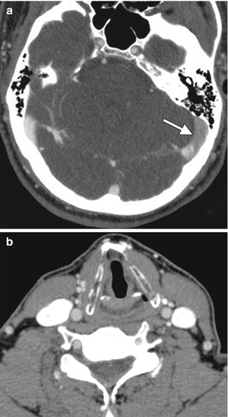
Fig. 2.7
Suboptimal contrast bolus timing. (a) Axial CT venogram of the brain that was acquired too early shows weak opacification of the left transverse sinus (arrow), thereby potentially mimicking venous sinus thrombosis. (b) Axial CTA of the neck in a different patient, performed for the evaluation of arterial structures, shows much greater opacification of the venous structures than the arterial structures, indicating that the scan was acquired too late
The appropriate CT scan delay can be estimated using a test-bolus or a bolus-tracking technique (Fig. 2.8) in order to account for differences in cardiac output among patients. The duration of injection also affects CT scan timing. Rapid injection of contrast agent is desirable to maximize arterial enhancement in CTA and to depict hypervascular tumors. Alternatively, concentrated contrast material can serve to increase iodine delivery rate, although this tends to be more viscous. A saline flush improves contrast enhancement and the efficiency of contrast material use, reduces artifacts, and is particularly beneficial when the total volume of contrast agent is small. The use of lower CT tube voltages, such as 80–100 kVp, yields stronger contrast enhancement for a given injection of contrast agent.
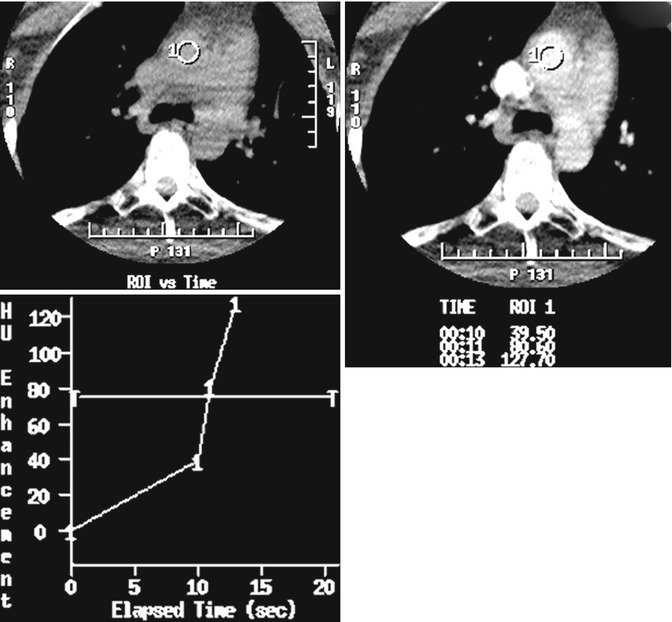
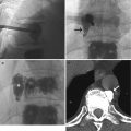
Fig. 2.8
Contrast bolus-tracking technique. Screen capture image in preparation for a neck CTA shows a region of interest drawn over the ascending aorta and a graph depicting the corresponding attenuation measurements (HU) at sequential time points. Once a threshold attenuation value is reached within the ascending aorta, scanning of the neck ensues in order to ensure adequate opacification of the neck vasculature
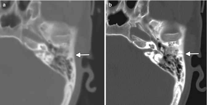
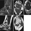
2.3.2 Improper Kernel Selection and Slice Thickness
Different reconstruction kernels (“filters” or “algorithms”) can be selected for the post-processing of raw data in the scanner. The two main types of reconstruction kernels are bone (sharp) and soft tissue (smooth) algorithms. The choice of kernel affects the image quality and there is a trade-off between spatial resolution and noise. A smooth kernel generates images with lower noise but with lower spatial resolution, while a sharp kernel generates images with higher spatial resolution but higher image noise. The selection of reconstruction kernel depends upon the clinical indication. Smooth kernels are especially useful for the evaluation of the brain and liver in order to minimize image noise and optimize the detection of lesions with intrinsic low contrast. On the other hand, sharp kernels are useful for the evaluation of bony structures due to the clinical requirement of high spatial resolution, especially fractures.
In general, lower radiation dose can be used in conjunction with sharp kernels than with smooth kernels. A related reconstruction parameter is slice thickness, which also has implications on spatial resolution, image noise, and radiation dose. The use of inappropriate reconstruction kernel can lead to diagnostic errors. For example, implementation of a soft tissue kernel with large slice thickness can obscure subtle fractures (Fig. 2.9). Conversely, the use of high-spatial-frequency reconstruction algorithms with peripheral edge enhancement can lead to a false-positive diagnosis of calcification in a small uncalcified lung nodule.