Fig. 50.1
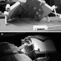
A typical setup for navigation using a C-arm is shown. The therapeutic object is positioned on the operating table, and dynamic reference bases (DRB) are affixed. The C-arm acquires the relevant images. The marker grid is attached to the image intensifier tube. It consists of two calibration plates for undistortion and calibration of the image and of reflective spheres to locate the spatial position of the C-arm in relation to the patients’ anatomy
One of the advantages of fluoroscopic navigation is its versatility. The image acquisition and registration process occur simultaneously. This means that the virtual object does not have to register to the therapeutic object in an additional step intraoperatively (see registration techniques below), but that the registration is replaced by a calibration process during image acquisition. The navigation system’s computer can combine the information regarding spatial orientation of the DRBs provided by the camera system and the imaging information supplied by the image intensifier equipped with the marker grid (Fig. 50.1) [18]. Through this feature, new images can be obtained repetitively during an intervention. This is especially useful in trauma surgery where the therapeutic object is not structurally stable and also in spine surgery where each vertebra is considered a solitary therapeutic and virtual object. Another advantage is the significant reduction of the radiation hazard to the patient and the operating room staff. In the light of the above-named advantages, yet several disadvantages have to be pointed out. First, despite computation, the actual image remains a 2D image that lacks the detailed information provided by true multiplanar images as derived from CT scans, for example. Sources of error furthermore can be found during image acquisition (poor quality, e.g., in obese patients, inadequate adjustment of the C-arm in regard to true lateral or anteroposterior plane), image calibration, and finally also computation of the calibrated images.
Iso-C 3D
With the evolution of imaging techniques, a C-arm image amplifier named Iso-C 3D (Siemens AG, Erlangen, Germany) was developed. The rationale behind this imaging modality was to combine advantages of computed tomography and fluoroscopy at the same time – the versatility of fluoroscopy and the three-dimensional dataset of a CT scan [19, 20].
Technically, the Iso-C 3D allows for acquisition of a three-dimensional image by performing a 190° orbital scan with the central beam at an isocentric position within the C-arm. During this scan, approximately 50–200 digital radiographs are obtained [21]. These projection images can then be mathematically converted into an image with similar resolution to a CT scan. Analogous to applications using fluoroscopy, Iso-C-based systems allow for ongoing reassessment of the situation, by enabling repetitive scans intraoperatively. Furthermore, just like the fluoroscopy-based navigation algorithms, a separate registration step is not needed, since an offline calibration process replaces it after image acquisition. Clinical application of Iso-C 3D-based navigation has been proven feasible in trauma surgery of the extremities and the cervical and thoracolumbar spine, where the isocentric scan can performed freely without interfering anatomic structures [20, 22, 23]. Disadvantages of this method include the need for a special fully radiolucent table; the decreased image quality, for example, at the cervicothoracic junction; the shoulder joint or in obese patients; and the technical fact that the field that can be encompassed by the isocentric scan is of limited size (approximately 12 cm3).
Image-Free Navigation Techniques
Some navigation applications do not employ pre- or intraoperative imaging; they are so-called image-free systems. These applications entirely rely on intraoperative acquisition of anatomical landmarks, which are digitized by tracked pointing devices and then used to represent the virtual object. This is also called surgeon-defined anatomy. The operating surgeon is prompted by the navigation application to provide information about the spatial location of predefined landmarks, e.g., the femoral condyles, the line of Whiteside’s, and the lateral and medial malleolus in image-free total knee arthroplasty. Besides landmark digitization using pointer devices, image-free navigation applications also use pivoting maneuvers in order to define inaccessible landmarks, e.g., the hip joint center as the center of femoral rotation. Combining information derived from landmark digitization and pivoting maneuvers, the navigation application is capable of correlating the positions in space and computing a virtual coordinate system without any other imaging information. With this information, parameters such as the mechanical axis and ligament balancing, as well as the flexion and extension cuts in total knee arthroplasty, can be controlled for.
A further developed and more sophisticated method of image-free navigation is the application of bone morphing [24, 25] by using statistical shape models [26–28]. Statistical shape models are derived from geometrical analysis from a set of shapes, in which statistics are used to describe morphogeometric properties of similar shapes, e.g., the human proximal femur. Usually, the data for calculation of statistical shape models is derived from high-resolution CT scans or laser surface scans from cadaveric bones. By employing a principle component analysis (PCA) a mean model of the anatomy and the main variations in shape can be computed and stored. Intraoperatively, sparse data, which can be collected by digitization of anatomical surface points, automatic segmented fluoroscopic images [29] or ultrasound images [27], can be used to extrapolate a virtual model of the patient-specific anatomy by calculating a linear combination, the mean shape, and the most significant variation modes. As stated above, digitization of the anatomy in terms of bone morphing is frequently used in commercially available navigation systems. The use of calibrated fluoroscopy and ultrasound for obtaining the sparse data is still rather experimental. However, being able to create an accurate virtual model without preoperative imaging and without the need to perform an extended surgical exposure in order to perform bone morphing holds a promising potential for application during arthroscopic or less-invasive surgical interventions.
Registration Techniques in Orthopedic Surgery
As stated above, surgical navigation systems utilize a virtual object that is derived from the therapeutic object by various means. During surgery, a dynamic reference base is rigidly attached to the patient’s anatomy. This DRB defines the coordinate system of the surgical object. By aligning the virtual object to the surgical object through computation of a transformation, the relationship between both objects is defined. This step is called registration or matching [29–31]. For performance of registration, different techniques are available which are divided into rigid and deformable registration techniques [32]. Most of the registration techniques used in orthopedic surgery are rigid registrations, since bone itself is a rigid and non-deformable structure. The geometric transformation is based on rotation and translation. Examples for rigid registration techniques include feature-based registration, fluoroscopic- and ISO-C 3D registration, and ultrasound registration. Deformable algorithms instead are used with the above-described statistical shape models. In these cases, there is no complete 3D dataset available for creation of the virtual model. Sparse data derived from bone morphing, ultrasound, or fluoroscopy is used for the registration procedure. The geometric transformation here cannot be simplified to rotation and translation, since spatial relations between two points are rather stretched and deformed.
Feature-Based Registration Techniques (Location of Fiducial Markers, Paired-Point-, Surface- and Restricted Surface Matching)
This registration technique was used in the first generation of surgical navigation systems in orthopedic surgery and is still widely employed in current applications [30]. It is based on recognition of paired points in the therapeutic and virtual object. These paired points may be fiducial markers that have been implanted prior to the preoperative imaging or prominent anatomic structures that can be easily assessed during surgery. Implantation of fiducial markers is medico-ethically questionable, since it requires an additional invasive procedure with all the associated risks. Hence, the digitization of anatomic structures is preferred. In order to perform any registration procedure, a DRB is affixed to the patient’s bone (Fig. 50.2). Afterwards, usually 3–5 points are defined on the virtual object, and subsequently the same points are digitized on the therapeutic object using a digitizing stylus (Figs. 50.2 and 50.3a). Another feature-based method of registration is the surface matching. While in paired-point matching the structures to digitize are defined, surface matching relies on an iterative closest point algorithm (ICP) [29–31], which means that scattered points distributed over the anatomy of the therapeutic object are approximated to the closest resembling points on the virtual object by geometrical transformation (Fig. 50.3b). In the absence of fiducial markers, the accuracy of paired-point matching alone may not be sufficient. This can be due to difficulties in recognizing the predefined points in situ or also due to soft tissue interferences. Surface matching based on the ICP algorithm may also lead to inaccurate results due to errative calculation during the iterative process. Hence, Bächler et al. introduced a so-called restricted surface matching, which combines and improves both presented registration techniques in order to meet the accuracy requirements in computer-assisted orthopedic surgery [33]. The advantage of feature-based registration algorithms is their accuracy. The disadvantage is that the anatomy needs to be exposed quite invasively in order to perform the digitization. Hence, it is not applicable to arthroscopic and many less-invasive procedures.
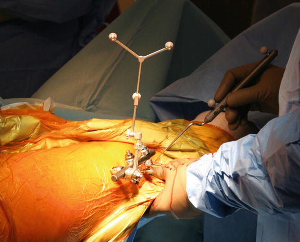
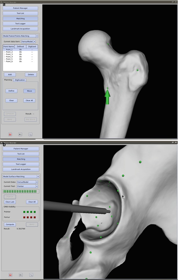
Fig. 50.2
The surgical site during a rigid registration procedure is shown. The dynamic reference base (DRB) is rigidly affixed to the patient’s bone. A digitizing stylus is used to locate anatomic paired points on the therapeutic object, which have been predefined on the virtual object. In this case, passively infrared light-reflecting spheres are attached to the DRB and stylus. Problems with these passive optical systems may derive from line-of-sight disturbance and interference by other light-emitting sources (OR lamp), and care has to be taken not to contaminate the spheres with blood, since the reflective capabilities are otherwise largely reduced
Fig. 50.3
(a) A screenshot of a paired-point matching procedure is depicted. The surgeon predefines prominent anatomic structures such as bumps and grooves on the virtual object, which are feasible to reach during the intervention. In this case, the chosen structures are represented by the green dots along the greater and lesser trochanter, as well as the femoral head-neck junction. After establishing the surgical exposure and at the time of registration, the navigation system prompts the surgeon to digitize the paired points on the therapeutic object (green arrow). This procedure may be error prone since it also depends on surgeon-machine interactivity. This is why it is frequently combined with a surface-matching procedure (b), then referred to as a restricted surface matching. (b) A screenshot of a surface-matching procedure at the pelvis is depicted. A scatter of points (green dots) around the region of interest is collected with a digitizing stylus. Through a mathematical similarity function, the most closely resembling points between therapeutic and virtual object can be calculated. The surface matching is frequently applied in addition to a previous paired-point matching (a), resulting in a restricted surface matching. In an iterative procedure registration accuracy can be improved
Fluoroscopic Registration and ISO-C 3D Registration
Apart from the invasive registration procedures described above, attempts have been made to integrate the C-arm into the registration process for noninvasive registration. Whereas merely fluoroscopy-based navigation does not have a registration step, tracked fluoroscopic images can be used to perform a 2D to 3D registration to a virtual object that has been generated from a preoperative CT scan [34–37]. The computer generates digital radiographic reconstructions (DRR) from the available 3D dataset, and the resulting 2D images are compared using a choice of similarity measure. The accuracy of the registration process is largely dependent on this calculation, which can be easily distorted by interventional instruments within the picture. Furthermore, a radiolucent table and preferably a prone or supine positioning of the patient are required in order to obtain images of sufficient quality. When using an ISO-C 3D for registration, a 3D image of the therapeutic object (obtained as described above) can be registered to the 3D virtual object derived from the preoperative CT scan. Since two sets of images with similar properties are being used, this is also called image fusion-based registration. Feasibility of this method has been proven [38]. Both 2D-3D and 3D-3D registration techniques do indeed not require invasiveness; however, in comparison to the above-described restricted surface matching, they lack robustness, accuracy, and reproducibility.
Ultrasound Registration
Ultrasound registration can be used similar to the above-described restricted surface matching due to its capability to percutaneously detect bony landmarks (e.g., the anterior superior iliac spine) and surfaces [39, 40]. The tracked images can then be registered to a preoperative CT scan [41] or even to statistical shape models [27] as a deformable registration (see below). Similar to the above-described less-invasive techniques, feasibility was proven, but current field of research is maintenance and improvement of reliability and reproducibility of those methods.
Deformable Registration Procedures
As stated above, the registration procedure is considered deformable, when no complete set of 3D data is available for construction of the virtual object. This is the case in image-free navigation applications. While systems that rely on surgeon-defined anatomy often only calculate an abstract virtual object, which is however providing sufficient information regarding spatial location of important points and angles, other systems employ statistical shape models (see above) in order to create the VO. The dataset available through these models is not complete, and during the registration procedure, the input data helps the computer to generate a sufficiently accurate virtual model. Methods of data input include bone morphing [24, 25], calibrated x-rays [42], or ultrasound [27, 43]. The mean information of the statistical model is taken and mathematically deformed to generate a model as similar as possible to the input data. Incorporated in commercially available navigation systems, especially bone morphing as a registration modality has found clinical acceptance.
Registration Accuracy
After establishment of the virtual model and performance of the registration procedure, it is mandatory to verify the registration accuracy before proceeding with navigation-dependent surgical steps. Although difficult to quantify, there are several error quantifications, which have been described for paired-point rigid registrations using fiducial markers [31]. The most frequently used parameter is the roots mean square error that is calculated for the error between the detected and the digitized fiducials during the registration procedure and displayed as an accuracy measure by most commercially available navigation systems. A more clinically applicable and simple approach is the use of a digitizing stylus to touch the therapeutic object or instruments with its tip that mostly has a known length. Should the tip be obviously off the target, then registration accuracy might not be sufficient and the registration procedure has to be repeated.
Finally, it needs to be stated that the position of the dynamic reference bases may not be changed after the registration process. This is not the case for general movement of the limb, since the reference bases are “dynamic” (see above) and also not for temporary detachment during the surgical steps that do not require navigation. It rather refers to the position of the base in regard to its affixation to the patient. Some systems use magnetic clamps or screw mechanisms in order to detach and reattach the DRB. When put back on, the DRBs need to have exactly the same orientation as before, which means that the bony anchorage (frequently Schanz screws) as well as the orientation of the clamping mechanism should not have changed. In case of accidental DRB dislocation during surgery, the registration procedure will have to be repeated. In the case of a CT-based navigation, this might not be possible, since TO and VO might not be the same anymore due to changes made during the operation. In this case, the navigation has to be aborted and the operation needs to be conducted conventionally.
Clinical Applications
Total Hip Arthroplasty
With the advent of surgical navigation, the application of these techniques to orthopedic surgery of the hip and pelvis initiated with navigation of pelvic osteotomies [3] and later computer-assisted placement of the acetabular and femoral component in total hip arthroplasty [44, 45].
The impetus for the developing applications of surgical navigation to hip arthroplasty derived primarily from the difficulty in ensuring correct acetabular component positioning. Malpositioning of the acetabular component is the most common technical problem associated with total hip arthroplasty and is clearly associated with increased incidences of prosthetic impingement, hip dislocation, wear, wear-associated peri-prosthetic bone resorption, and component loosening [45–48]. Acetabular component positioning is compromised by the fact that the pelvis moves significantly during surgery [45] and the patient is frequently malpositioned at the time of acetabular component insertion [49]. Although some newer and more sophisticated mechanical tools showed good results [50], conventional mechanical jigs to guide acetabular component insertion are clearly inadequate [51]. Apart from acetabular orientation, implantation depth and version of the femoral component is another parameter to control for [52]. Associated with femoral and acetabular component positioning is the intraoperative assessment of leg-length change during surgery. Equal leg length is important, since excessive lengthening or shortening leads to patient dissatisfaction and some degree of dysfunction, hip instability, and at the worst premature failure of the prosthetic construct [52–55].
Application of surgical navigation to total hip arthroplasty proved to be a valid means to control for the abovementioned parameters. Meta-analyses and comparative studies between total hip arthroplasty performed with and without surgical navigation have shown that component positioning was more tightly controlled using navigation and that malpositioning-related complications, such as early dislocations, could be significantly reduced [7, 56–62]. Performing total hip arthroplasty with the aid of surgical navigation hence has a clear benefit for patient safety and long-term outcome of this procedure.
Total Knee Arthroplasty
The goal of total knee arthroplasty is to relieve pain and symptoms from gonarthrosis and to regain function by replacing the arthritic joint surfaces and by restoring mechanical axes and alignment of the limb. Frequently, progression of arthritis in the knee joint has not only led to a multi-compartmental loss of cartilage. Due to the permanent inflammatory process within the joint, the surgeon frequently encounters grossly changed mechanical axes in the valgus and varus direction as well as associated contracture of the ligaments and joint capsule. Hence, important parameters influencing clinical outcome and longevity of the prosthesis include accurate component placement and restoration of the limb axis [63], as well as balancing of the soft tissue structures [64, 65] surrounding the knee joint. Conventional techniques for performance of total knee arthroplasty employ intramedullary rods and jigs to control for the tibial and femoral cuts correcting alignment and slope, as well as mechanical tension devices to control for ligament balance. The use of surgical navigation systems in total knee arthroplasty was intended to improve control over these crucial parameters during surgery. It also anticipated that employment of such systems would create benefits in terms of reduced blood loss and embolism since the medullary canal remains closed [66]. Furthermore, it is deemed possible to improve component positioning, especially by reduction of rotational malpositioning. Finally, the possibility to accurately perform ligament balancing [67] was proposed.
However, meta-analyses and comparative studies have failed to show a significant advantage of navigated total knee arthroplasty compared to conventional techniques [66, 68, 69]. This might be due to the fact, that in contrast to total hip replacement, the outcome of total knee arthroplasty is more dependent on a balance between component positioning and tension of the surrounding soft tissue. The latter seems to be reliably adjusted using mechanical tensioning devices. Still, in the absence of significance, surgical navigation aided in reducing radiographic outliers of component positioning. Whether this will have an effect of long-term outcome remains to be seen.
Sports Medicine
Surgical navigation has not been widely used in sports medicine [70]. Fields of application include ligamentous surgery around the knee joint [71]. Especially, tunnel placement during reconstruction of the anterior cruciate ligament can be performed with the help of computer assistance [72–74]. While comparative studies have shown improved consistency of tunnel placement when using surgical navigation, clinical outcome was not significantly improved. Again, long-term implications of this finding are subject to further research. Besides ACL surgery, computer assistance has also been used as a measurement means during high tibial osteotomies [75–77]. In the absence of comparative randomized trials, an increased accuracy in regard to achieving the preoperatively planned correction angles, as well as a decreased variability in terms of deviation from the preoperative plan, has been reported for the navigated procedures.
Spine
Together with acetabular component orientation in total hip arthroplasty, pedicle screw placement was among the first surgical orthopedic techniques realized with the assistance of a navigation system [2]. The basic principle for application to spine surgery is universal. The navigation system is used to assist the surgeon during placement of screws by visualizing parameters such as entry point and screw trajectory. While the lumbar vertebrae provide comparably broad pedicles, where establishment of the screw canal can be estimated through tactile information using the finder, the thoracic and especially cervical spine challenge the surgeon with narrow and either less or more convergent pedicles, increasing the rate of possible screw malpositioning. In the upper cervical spine, surgical navigation can be used for fusion of C1 and C2 in traumatic or degenerative instabilities using the Magerl technique or for fracture stabilization of C2 using the Judet technique [78]. In the thoracic and lumbar spine, navigation assists during pedicle screw placement in corrective surgery of congenital deformities [79] or during posterior stabilization in trauma or degenerative disease [15, 22, 23, 80]. Regarding the type of navigation, the methods of choice include fluoroscopic, CT-based, and ISO-C 3D-based algorithms. It needs to be stated that each vertebra has to be treated like a single therapeutic object and thus needs to be registered or calibrated separately. For surgery at the cervical spine or cervicothoracic junction, CT-based methods have proven more accurate than fluoroscopic methods. However, with the advent of the ISO-C 3D technique, the possibility to intraoperatively obtain 3D images of comparable quality has equalized this advantage [15, 22, 23, 78, 81]. In addition ISO-C 3D offers the chance to react to trauma-related changes of the anatomy, which might occur, e.g., during positioning of the patient. As already shown for the other fields of application for surgical navigation, meta-analyses and comparative studies between navigated and non-navigated spine surgery procedures proved, that regardless of the type of navigation, the accuracy of pedicle screw placement was higher and the number of outliers was reduced [80].
Trauma Surgery
Application of surgical navigation to select cases of musculoskeletal trauma offers several advantages compared to treatment using conventional methods. In general, navigation allows for fracture reduction and fixation, positioning of implants, and guidance for screw trajectories by providing multiplanar views to the surgeon. At the same time, it reduces radiation exposure intraoperatively and promotes the use of less-invasive techniques due to improved orientation [82].
As stated above for spine surgery, fluoroscopic or ISO-C 3D-based applications have established in trauma surgery. This is simply due to the fact, that in contrast to CT-based applications, which rely on a rigid preoperative CT scan, these algorithms respect morphologic changes of the fractured bone, which might occur during patient transport, imaging, and preoperative positioning. The ability to repeatedly acquire new images, even in 3D when using ISO-C 3D, is hence a tremendous asset.
At the femur and tibia, surgical navigation is used for screw placement during reduction and internal fixation of femoral neck fractures, reduction and screw fixation of tibial plateau fractures, entry point definition and distal locking of intramedullary nails, as well as fracture reduction and fixation of the long bones with different plates [11, 12, 82–85]. At the pelvis, sacroiliac screw stabilization for disrupture of the posterior pelvic ring and osteosynthesis of some acetabular fractures can be performed percutaneously guided by surgical navigation. In these two interventions, accuracy of screw placement is crucial, since the corridors for safe placement are quite narrow [86]. Traditionally, numerous inlet or outlet images of the pelvis are necessary intraoperatively in order to assess reduction and screw placement. Minimization of radiation hazard is thus certainly benefit [87, 88].
In trauma surgery probably more than in the elective surgery cases, a clear disadvantage of surgical navigation might be the additional time needed to set up the system and perform the necessary image acquisition, registration, or calibration. In cases where the surgeon is confronted with a life-threatening situation and where damage control surgery is the treatment of choice, it is obvious that surgical navigation is not a suitable alternative.
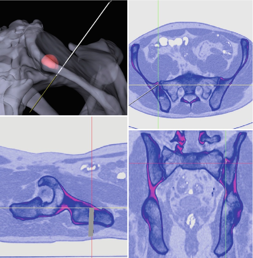
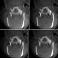
Resection of Musculoskeletal Tumors
After successful evaluation in reconstructive orthopedics and trauma, surgical navigation has recently been introduced to orthopedic tumor surgery [89–94]. Few research groups have succeeded in performing navigated resection of malignant tumors with the help of a surgical navigation system. Krettek et al. [91, 92] present two cases – one periacetabular chondrosarcoma and one sacral chordoma, resected with the guidance of CT-based navigation. They were able to perform a restricted surface matching with a registration accuracy of less than 1 mm and histopathologically achieved an R0-resection. So et al. [93] developed a workflow for computer-assisted resection of bone tumors. They operated on 18 patients with various tumors at various locations, including the long bones and pelvis and sacrum. They acquired preoperative CT and MRI images and performed image fusion. The BrainLAB VectorVision spine software (BrainLAB Ltd., Hong Kong) was used. Two different registration modalities were used – restricted surface matching, as well as intraoperative CT-fluoro matching was performed, and a registration accuracy of <1.9 mm was accepted. All the patients had an R0-resection. The CT-fluoro group was more accurate, whereas they noted two failed restricted surface-matching procedures. In two other studies by Cho et al. [89, 90], one osteosarcoma of the proximal femur, one malignant fibrous histiocytoma of the proximal femur, and one sacral chondrosarcoma were resected with computer assistance. For preoperative imaging, K-wires were implanted as fiducial markers around the region of interest, and a CT scan was performed thereafter. Additional MRI data was used for image fusion. The navigation system used was an In2Fusion System (Cybermed, Seoul, Korea). For intraoperative registration they used a paired-point matching done by digitization of R0-resection was achieved. Ecker et al. performed computer-assisted resection of a sacral mass [95]. A custom-made CT-based navigation application was used (Fig. 50.4). A restricted surface matching with an RMS error of 0.3 mm was applied, and the mass was resected in toto. Summarizing, application of surgical navigation to orthopedic tumor surgery is an emerging trend. It may aid in safely achieving curative resection of musculoskeletal tumors, especially when located remotely, or in vicinity of neurovascular structures.