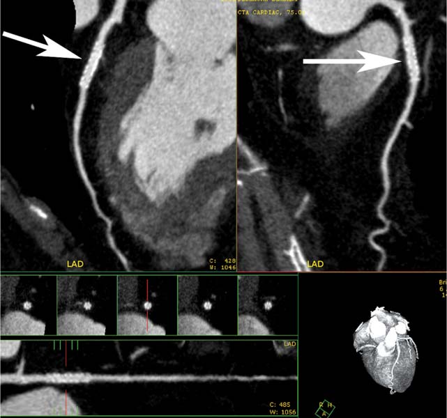
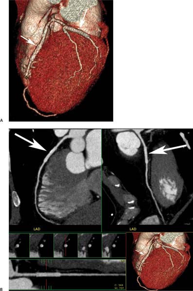
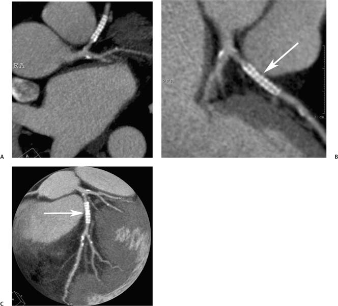
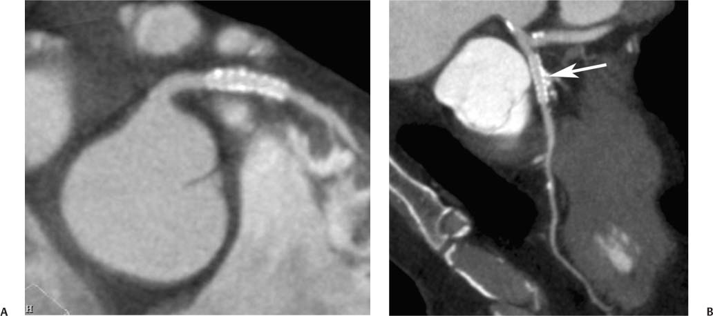
7 The introduction of percutaneous transluminal coronary angioplasty (PTCA) to clinical practice by Grüntzig in 1977 offered a less invasive alternative to conventional bypass surgery for patients in need of coronary artery revascularization.1 Early comparative studies suggested that even in cases of multivessel coronary artery disease long-term mortality rates of patients treated by PTCA were similar to those undergoing more invasive surgical bypass procedures.2,3 Enthusiasm for these results was tempered by high rates of restenosis following PTCA, often resulting in a need for repeat revascularization procedures. Implantation of metal stents during PTCA, first performed by Sigwart and Puel in 1986, became standard during the 1990s as a result of the associated improvements in procedural and clinical outcomes. Despite this advance, restenosis occurred in 22.0 to 31.6% of stented patients, often resulting in a need for repeat invasive procedures.4,5 Even with the dramatically reduced rates of restenosis for newer drug-eluting stents, many patients require repeat catheterization. Recent data suggest that late thrombosis of drug-eluting stents occurs more frequently than initially reported, often with devastating consequences.6 Acute thrombosis invariably presents with signs of epicardial injury that is best treated by urgent catheterization, but restenosis usually presents subacutely. CT has emerged as a diagnostic alternative to invasive coronary angiography for assessment of coronary artery disease and can often provide interpretable images of stented coronary vessels (Fig. 7.1). CT imaging of stented segments remains subject to technical limitations. Early electron-beam computed tomography (EBCT) studies imaged coronary calcium and used quantitative calcium scoring to predict restenosis following angioplasty. In a study of 28 coronary arteries treated by PTCA, there was a 71% three-month restenosis rate among 17 vessels with moderate or heavy calcification but not a single case of restenosis among 11 noncalcified or only mildly calcified vessels.7 A calcium score of 27 or greater predicts restenosis within 6 months (sensitivity 73%, specificity 67%).8 Furthermore, an increase in the incidence of periprocedural complications has been described for angioplasty of calcified vessels. Visualization of the stent lumen with EBCT is limited. EBCT protocols have relied on coronary flow distal to stents to determine patency.9–12 This technique is subject to several limitations. Foremost, resting coronary flow is not significantly diminished in the post-stenotic segment until obstruction exceeds 85%, even when lesser degrees of stenosis are clinically important. Furthermore, collateral blood flow may result in opacification of a vessel beyond an occlusion. In vitro studies have highlighted the tendency of EBCT to underestimate stent length and overestimate diameter, with resulting poor sensitivity (65%) and positive predictive value (69%) for in-stent stenosis.11 Although multislice–multidetector computed tomography (MDCT) offers improvements in spatial and temporal resolution, imaging of stents with this newer technology is also limited by technical issues related to stent architecture and CT imaging. CT imaging of stents is complicated by variations in stent composition and structure that result in differences in radiopacity and CT appearance.13 Most stents in use today are made of 316L surgical stainless steel, an alloy composed primarily of iron with a small amount of nickel.14,15 Other metals, including cobalt alloys, nitinol, and tantalum, are used in a smaller percentage of commercially available stents.13 Many stents are coated with compounds—most commonly heparin, gold, phosphorylcholin, carbon, or chromium oxide—intended to reduce biological activity and improve biocompatibility.15,16 In addition, there is considerable variability between stents with respect to size, mesh design, and radiopacity.14 Stent materials result in variable degrees of CT artifact. Radiopaque metals, although helpful to the cineangiographer in the cardiac catheterization laboratory, result in artifact and decreased visibility of the stent lumen when imaged by CT (Fig. 7.2). Stent densities, when imaged by CT, range from 600 to more than 1500 Hounsfield units (HU).14,15,17 Higher attenuation values are associated with greater CT artifact, limiting visualization of the internal stent lumen. Tantalum in particular results in a greater amount of artifact than stainless steel or nitinol.13,16 Stent weight and strut diameter have been shown to correlate with artifactual luminal narrowing on CT.16 Radiopaque markers at stent margins, intended to aid cineangiographic visualization, significantly decrease lumen visibility.18,19 Mahnken and colleagues examined, in vitro, 10 different coronary artery stents, including a novel biodegradable stent made from polylactide with a microcellular foam structure.18 No beam hardening occurred with the polylactide stent because of its construction from a low-attenuation material. As a result, the polylactide stent showed greater luminal visibility than the metal stents. A more recent in vitro evaluation of 29 different stent types with dual-source CT demonstrated magnesium to be a more favorable stent material compared with more common materials, including steel, cobalt–chromium, or tantalum. In this analysis a magnesium stent exhibited the least artifacts, with a lumen visibility of 90%. Most other stents exhibited a lumen visibility of 50 to 59%.20 Fig. 7.1 Patent left anterior descending artery (LAD) and circumflex stents. (A) Volume-rendered surface display demonstrates the presence of stents in the LAD and circumflex arteries (arrows) but does not provide an evaluation of the internal stent lumen. (B) Curved maximum intensity projection images based on vessel tracking in the LAD clearly demonstrate a patent stent (arrows) with mild overexpansion of the LAD. Fig. 7.2 Patent stent in the proximal left anterior descending artery (LAD). Images are compromised by blooming artifact. (A,B) Maximum intensity projection (MIP) images demonstrate a patent stent in the proximal LAD (arrow). The stent lumen appears narrowed by blooming artifact from the stent wall. (C) Globe MIP with thin-section depiction of the LAD. The internal lumen is obscured by ridges from blooming artifact (arrow). RA, right atrium. Stent size plays a particularly important role, as the blooming effect created by high-density stent material tends to be a relatively static phenomenon, resulting in greater degrees of luminal obscuration with smaller stents.17 Artifact from high-density stent material leads to increased intraluminal density, overestimation of stent outer diameters, and underestimation of inner lumen diameters. As a result, the lumen of larger stents may appear artifactually smaller, whereas the lumen of smaller stents may appear to be occluded.17 CT-generated artifical luminal narrowing in stainless steel stents may be as great as 62 to 94.3%, depending on stent size.16 In clinical practice, most coronary stents are 3 mm or smaller.4 In vitro studies have tended to include a disproportionate number of larger-diameter stents, thus overestimating the ability of MDCT to characterize stent lumens and detect in-stent restenosis.17,21 Schuijf and colleagues imaged 68 stents in 22 patients using 16-slice MDCT. Of 15 uninterpretable stents, 13 had diameters 3 mm or smaller, whereas only 2 of 19 larger stents were uninterpretable. Additionally, stent strut thickness of 140 μm or greater was associated with significantly decreased lumen interpretability. Another study reported that only 50% of stents 3 mm or smaller were interpretable, compared with 81% of larger stents.22 In a study of left main coronary artery stents, 27 of 29 (93%) stents with a mean diameter of 3.9 mm were of sufficient quality to permit lumen visualization.23 The progression from 4- to 64-slice MDCT has been accompanied by progressive improvements in spatial and temporal resolution.16,17 Early case reports suggested that even with lower-resolution scanners (1.25-mm slice thickness), MDCT has utility to visualize the lumens of stents in larger coronary arteries, such as the left main and proximal left anterior descending.24–26 However, visualization of the stent lumen is limited by partial volume effects and beam hardening.27 Comparisons of 4- and 16-slice MDCT have demonstrated only a modest improvement in stent lumen visualization with 16-slice collimation.18,28 Newer 64-detector row CT scanners provide improved z-axis resolution with isotropic pixels (resolution about 0.5–0.6 mm in all directions). Isotropic imaging minimizes the importance of stent orientation, and improved resolution minimizes blooming artifact. In one study, stent lumen diameter imaged by 64-slice CT at multiple stent orientations averaged 53.4% of the true lumen as confirmed by standardized caliper measurements, representing a 10% improvement over 16-slice CT.19 Seifarth and colleagues compared 16- and 64-slice scanning of 15 different coronary stents at various orientations. The 64-slice scanner provided better overall images, with decreased artificial luminal narrowing and similar luminal attenuation values for stented and unstented segments (Figs. 7.3 and 7.4). Images obtained with the 64-slice scanner did not appear to be significantly affected by stent orientation.29 A more recent investigation focused on imaging of coronary stents with a prototype flat-panel detector computed tomography (FPCT). Isotropic images with slice thickness of 0.25 mm resulted in artificial lumen narrowing of only 16.1% compared with standardized caliper measurements. The superior spatial resolution of FPCT allowed for delineation of stent struts with minimal blooming artifact. Currently, FPCT remains subject to significant technical limitations, including poor temporal resolution, which does not allow in vivo cardiac imaging. Application of this technology to clinical patients remains a future consideration.30 Fig. 7.3 Proximal left anterior descending artery (LAD) stent. Two orthogonal curved maximum intensity projection views demonstrate a stent within the proximal LAD. The stent is widely patent without narrowing (arrow). At the bottom of the figure, there is a straightened lumen view of the LAD with short-axis (cross-sectional) views through the stent demonstrating the patent lumen. Fig. 7.4 Proximal left anterior descending artery (LAD) stent. Slab maximum intensity projection (MIP) versus curved reformat with tracking. (A) MIP image demonstrates patency of the proximal LAD stent. (B) Curved reformat image obtained by automated tracking of the LAD. This image demonstrates excellent visualization of the stent lumen because the tracked image depicts a thin section through the center of the stent (arrow). Thin-section images are required to view the lumen of a coronary stent. Slab maximum intensity projection images with a slab thickness of 0.5 to 1.0 mm may be centered within the stent lumen. However, the lumen of a stented segment, particularly the lumen of a long stented segment, may not be optimally visualized in a single plane. In many patients, tracked reconstructions with thin-section curved reformats may be useful to visualize optimally vessel lumen within a stent (Fig. 7.4). The use of an extended CT scale technique (ECTS) has been shown to improve visualization adjacent to cobalt screws and steel plates in porcine femur specimens.27 Most in vitro coronary stent imaging studies have used a standardized window width of 700 HU. Increasing window width to 1500 HU clearly decreases blooming artifact (Figs. 7.5 and 7.6), but clinical improvements in accuracy of stent assessment with ECTS have not yet been evaluated in a controlled study.29 Dedicated sharp-kernel reconstruction improves stent imaging by MDCT. A sharp kernel (B46) used in a phantom study with 16-slice MDCT increased mean visible lumen diameter from 31% to 54% of caliper-obtained measurements and decreased average luminal attenuation from 349 to 250 HU.28 Visualization and classification of artificial stenoses were poor using a standard kernel, with more than half of all stents either uninterpretable or interpreted with low certainty. Reconstruction with the sharp kernel significantly increased diagnostic accuracy; all stents were correctly classified as stenosed or nonstenosed, and 75 to 85% were classified with high certainty. Similar findings have been reported with 64-slice MDCT stent images, including significantly improved visualization of stent lumen and decreased overall lumen attenuation with the addition of a high-resolution kernel (Fig. 7.7).13 Patient-based protocols have reported decreases in artificial luminal narrowing from 27 to 37% down to 16 to 29% with a dedicated sharp reconstruction kernel.31,32 Both subcentimeter collimation and the use of a sharp kernel reconstruction result in increased image noise.13 Image noise may be reduced to levels approaching those associated with standard reconstruction kernels by use of noise-reduction filters.32 Improvements in stent lumen visualization and decreases in attenuation with the sharp kernel are maintained after processing with a noise-reduction filter. Dual-energy CT (DECT) is a promising technology that may improve the differentiation of tissues based on synchronous CT data obtained at two different tube energies.33
Coronary Stents
 Percutaneous Coronary Interventions
 Electron Beam Versus Multidetector CT
 Stent Characteristics
 CT Technical Factors
Number of Detectors and Z-Axis Resolution
Viewing Technique
Reconstruction Kernel
Dual Energy
![]()
Stay updated, free articles. Join our Telegram channel

Full access? Get Clinical Tree


