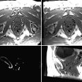
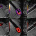
Fig. 12.1
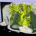
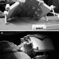
The overall setup for a CT-guided interventional procedure. The patient is positioned on the CT table (left) and scanned from the radiation-shielded control room (middle). The probe is aligned with respect to the lesion (right) and advanced under CT guidance
Any CT-guided procedure (e.g., a biopsy or RF ablation) can be divided into four steps as shown in Fig. 12.2. In the trajectory planning stage, the access route for the instrument is decided based on prior imaging and a current scan. A needle or a probe is then placed on the patient. In the third step, the needle/probe is oriented and inserted towards the lesion. Finally, a sample is taken; the lesion is sampled or ablated, or a catheter is deployed depending on the procedure being conducted. These steps are further detailed in the following paragraphs.


Fig. 12.2
Four steps in a CT-guided procedure
For trajectory planning, the patient is positioned either prone or supine depending on the location of the lesion and the preferred route of access. A single anteroposterior localizer radiograph is typically acquired to plan the scan in the region of interest. Typical scan parameters are 120 kVp, effective mAs of 90–300, 0.5 s gantry rotation time, 20 × 1.2 mm detector configuration, 1:1 pitch, 2.4 mm reconstructed slice thickness, 2.4 mm inter-slice interval, and reconstruction kernel (sharp vs. smooth) depending on the anatomy being visualized (effective mAs is defined as the product of tube current (mA) and time (s), divided by the pitch). Generally, the initial scan series is acquired at high dose, and with an extended scan length, to properly visualize and localize the lesion. Subsequent scan series are limited to the region of interest for the procedure being performed and are acquired at a reduced effective mAs to limit the radiation dose.
Intravenous conscious sedation is administered as required. The skin is aseptically prepared and draped, and 1 % lidocaine (Xylocaine; Astra, Wilmington, DE, USA) is administered locally to induce local anesthesia. Many times, a coaxial system composed of 19-gauge introducer needle (e.g., Chiba, Cook, Bloomington, IN, USA) and a 22-gauge aspiration needle (Cook) is used to gain access.
After a scout scan, a CT scan is performed with a radiopaque grid (e.g., E-Z-EM Fast Find Grid, E-Z-EM Inc., Westbury, NY, USA) placed on the patient to determine the access trajectory and skin insertion point. Then, a small incision is made at the insertion point to facilitate the needle, probe, or catheter entry. The shortest and most direct path is preferred, when feasible. Often the CT gantry is tilted so as to aid in negotiating through the structures along the way and to provide a clear path to the lesion. Most often, a hypodermic needle is first placed at the desired skin insertion point and a subsequent scan is performed to confirm the selected insertion point and the approach angle. Sometimes, multiple scans of the hypodermic needle are performed when the location/orientation of the hypodermic needle is changed or the CT gantry is tilted to optimize the access trajectory.
Once acceptable access trajectory and insertion site are selected, the hypodermic needle is replaced by the actual biopsy needle, the interventional probe, or any other instrument that is needed to be advanced under CT guidance. The desired needle or probe is advanced incrementally with intermittent CT scanning to assess the trajectory with small angular corrections performed when necessary. Once the target is reached, the action performed is procedure specific. For example, it may consist of fine needle aspiration, deployment of RF ablation probe, or placement of a drainage catheter. A final CT scan is typically performed after removal of the instrument to verify the appearance of the lesion and to check for any additional complications such as hemorrhage or pneumothorax.
Factors Affecting Procedure Complexity
In one study of CT-guided lung biopsy, it was shown that the needle orientation and insertion step accounts for over 50 % of the acquired CT scan series, illustrating that this is the most challenging part of the procedure [5]. The analysis also showed that the majority of scan series (and hence needle manipulations) were performed when the needle was outside the lung, illustrating that the strategy has the correct needle alignment before puncture of the pleura. Overall this study highlighted the sensitivity of targeting small, deeply situated lesions associated with a larger number of acquired CT scan series. This is due to the fact that small angular alignment errors result in large lateral displacements of the distal needle tip. As an example, an angular error of only 3° will result in a radiologist missing a 1-cm lesion at a 10-cm depth when aiming at its center.
Needle alignment for these procedures consists of aligning the needle in two angles. As was mentioned, the radiologist typically first aligns the CT scanner gantry so that a clear path to the target can be visualized, followed by alignment of the needle within the resulting scan plane. Selecting the correct gantry angle is difficult, because the radiologist has to mentally determine the correct needle angle in the craniocaudal direction in order to make the lesion, the skin insertion site, and the needle coplanar. As a result, the radiologist is often forced to adjust the gantry angle repeatedly and rescan in order to settle on a clear, non-vertical path to the target [5]. Once the correct gantry angle has been selected, precisely aligning the needle along the desired trajectory is difficult due to the effects of limited operator precision, gravity, tissue tension, and respiratory motion. Often this difficulty is exacerbated of limited subcutaneous soft tissue to adequately support the needle, and a number of clinical techniques are employed to support the needle (e.g., towels placed between needle and patient). Further, the needle has to be adjusted about a pivot point at the skin surface that may be several centimeters away from the lesion, making it difficult to accurately predict how manipulations of the needle outside the body will change the needle tip position inside. Apart from angular alignment errors, another potential source of error is the deflection of the needle due to the reaction force of the tissue acting on the asymmetric beveled tip as the needle is being inserted. Overall, these errors result in the inability of the radiologist to place the distal tip of the needle to the desired target within even an order of magnitude of the submillimeter and sub-degree measurements from the CT display. Figure 12.3 illustrates how alignment errors and needle bending result in the needle not hitting the desired target.
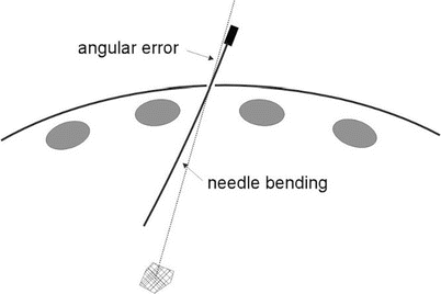

Fig. 12.3
Sources of targeting errors in image-guided, percutaneous interventions
During a CT-guided needle insertion, a radiologist may end up with the needle inserted deep into the body and then want to reposition the tip of the needle to a nearby point. For example, based on the aforementioned difficulties during needle insertion, there is a need for physicians to be able to correct for target errors in order to accurately sample tissue or treat disease. Another reason why a physician would want to reposition the distal tip of the needle would be to target a number of adjacent points in a tumor. This could be used to ablate multiple adjacent points in a tumor when treating a large or irregularly shaped tumor, or to sample a number of points in a tumor as a result of inconclusive diagnosis when examined by cytology or pathology because of the sampling regions of necrotic tissue. However, accurate reorientation of the needle inside the body is difficult, if not impossible, as there are forces from the tissue that resist the needle motion. Radiologists currently have two options; they can try and overcompensate when realigning the needle, or they can retract the needle and attempt to reinsert it along the correct trajectory.
CT Dosimetry
For interventional CT-guided procedures, the entire ionization effect is concentrated in a few slices (e.g., a small segment of the thorax for the lung biopsy). Therefore, it is important to consider both stochastic and deterministic effects of this mode of dose delivery. Historical data suggests that the stochastic risk associated with radiation exposure (e.g., tumor induction and hereditary effects) has no threshold for cancer occurrence: the risk increases linearly with patient dose. However, deterministic effects (direct damage to organs or tissue) have a threshold below which no direct radiation-induced damage to the body will occur; for skin 2 Gy or higher is required for local skin damage (acute skin reactions like erythema and epilation) to occur [6, 7].
The effective dose (E) is typically used to quantify the stochastic dose because it takes into account the doses received by all radiosensitive organs weighted according to their individual radiosensitivity [8]. The entrance skin dose (ESD) is the metric chosen to represent the deterministic dose to the skin of the patient [8].
Multiple tools for patient dose calculations are available. The ImPACT CT Patient Dosimetry Calculator (CTDosimetry.xls, www.impactscan.org) is a commonly used tool. This program contains the CTDI values normalized per 100 mAs for air (nCTDIair) and for the center (nCTDIc) and periphery (nCTDIp) of both body and head phantoms for a variety of scanners. To obtain the effective dose (E), the corresponding anatomic region scanned on a patient is noted from the CT images and prescribed on the mathematic phantom included in the program. The entrance skin dose can then be estimated using the CTDIp value that refers to the dose at 1 cm below the surface of a standard 32-cm body phantom. The anatomic location of the maximum entrance skin dose (ESDM) can be calculated by determining the overlap of all scans and their respective entrance skin dose.
There have been a number of recent studies that quantify the contributions of the CT scanning to the entrance skin dose and effective dose received by the patient [5, 8]. During interventional CT-guided procedures, the amount of acquired CT scan series is directly correlated with the maximum entrance skin dose. However, the effective dose is most largely influenced by the first planning scan since it covers such a large area of the body, and the subsequent more localized scans have less of an effect. For each procedure, it is essential that the above calculations are performed for typical parameter settings and scan lengths. One can also perform the dose calculations for any prior CT-guided procedure as all parameters needed for the calculation are readily available from the archived image data (provided all scans acquired during the procedure are saved and pushed to the PACS). This exercise is essential to ensure that the dose is below the required level for induction of erythema, epilation, and other deterministic and stochastic effects of radiation.
Recent Trends and Advanced Applications
C-Arm CT for Interventional Procedures
As mentioned earlier, radiography and fluoroscopy (R&F), C-arm angiography, and CT are the three main modalities used for interventional guidance. Traditionally, these modalities have remained separate and are available in separate interventional suites. Recently introduced digital flat-panel detectors could potentially satisfy the disparate demands of these three different modalities, making a combined 3-in-1 “omniscanning” machine possible. Early results demonstrate that C-arm CT using an area detector mounted on a C-arm gantry can deliver the image quality required for intraoperative workup of vascular and musculoskeletal questions encountered in routine neuro-interventions [9]. The clinical utility of this new modality is currently evolving, and the indications for its use, and the associated protocols, are still being developed.
This section will discuss the applications of flat-panel detector-based C-arm CT in image-guided interventions. After a brief description of the flat-panel detector technology and its integration with the C-arm gantry, we will review examples that highlight the efficacy of this modality as an intraoperative problem-solving tool during interventions.
Digital Flat-Panel Detectors
A digital flat-panel detector uses a scintillator film, typically evaporated cesium iodide (CsI), to convert incident X-ray energy into visible light. The generated light is sensed by a photosensitive imaging array fabricated on a 2D amorphous silicon flat-panel which replaces the photographic film of conventional radiography. The scintillator is deposited directly on the photosensitive elements to ensure intimate optical contact which, when combined with the novel columnar structure of the CsI, serves to significantly enhance the efficacy with which the information in the X-ray image is preserved in the electronic image. Each pixel in these imagers contains a photosensitive diode, which generates and stores a signal charge, and a thin-film field effect transistor to transfer the collected charge to external circuits [10].
With the advent of such amorphous silicon-based digital X-ray flat-panel detectors, it is possible to capture video frame rate, two-dimensional digital X-ray images that preserve high image contrast. Remarkably, this lightweight, compact profile detector can deliver a matrix of square detector elements, with 200 μm pitch, over an area as large as 41 × 41 cm2. As a result of this detector technology, the technological gap that existed between various X-ray modalities, and the prime reason for their separation, can now be filled potentially [11]. Both C-arm gantries and standard CT gantries have been used to house this detector assembly to make tomographic images available.
C-Arm Gantries Employing Flat-Panel Detectors
All major imaging equipment vendors now provide C-arm scanners that employ digital flat-panel detectors integrated with a C-arm gantry. The C-arm platform offers open architecture and easy patient access. As usual, one can use the C-arm for fluoroscopy and angiography. However, by putting the C-arm in a fast-spin mode while acquiring images, one can obtain projection data that can be converted into high-quality CT images. Therefore, it is now feasible to perform angiography, fluoroscopy, and volumetric CT imaging on the same platform, enabling a seamless integration of these heretofore-separate modalities.
For volumetric CT, the projection data is acquired using a detector pitch of 200 μm in the transverse direction and 200 μm in the vertical slice direction. Typically, 600–900 views are collected during a single rotation of the gantry. The flat-panel detector acquires data in real-time at the rate of 30 frames per second for full-panel readout at the native resolution of the panel [12]. Since approximately 600–900 projection views are required for adequate reconstruction, the volumetric image acquisition has to be carried out over 20–30 s. The projection data are corrected for gantry motion and beam hardening and are reconstructed with the Feldkamp cone-beam algorithm.
The native resolution of the flat-panel is typically 200 μm. After accounting for magnification and X-ray focal spot size, this yields an isotropic voxel resolution of approximately 150 μm. Generally, the flat-panel is operated in a 2 × 2 binning mode (i.e., the neighboring 4 pixels are averaged to increase the signal to noise ratio), and the resolution is of the order of 200 μm isotropic [13]. Therefore, compared to conventional MDCT scanners, these flat-panel-based C-arm CT improve the spatial resolution almost by a factor of 12 on a voxel-by-voxel basis.
Flat-panel-based C-arm CT also provides volumetric coverage: the entire head or neck can be scanned with an isotropic resolution of 200 μm (both in-plane and along the slice direction) in one rotation of the gantry. For the first time, this scanner opens the possibility of visualizing pathology as a resolution close to what is amenable histologically.
Imaging protocols that enable use of all three modes of a C-arm (fluoroscopy, angiography, and CT) interchangeably in the same procedure are currently being developed. Synchronization details between these three modes and the use interface are currently being investigated. When these modes are fully developed, complex scanning scenarios will be feasible [14]. For example, using the tomography mode, one will be able to compute a slice through the anatomy of interest. During the fluoroscopy mode, one will be able to view the location of a point prescribed on the tomographic slice. Such a facility will be useful in drilling or guiding a needle to a particular location on the CT slice, while exposing the patient to markedly reduced radiation from a fluoroscopic examination. The following features make these gantries an ideal imaging machine for image-guided interventions:
Ultrahigh, isometric resolution that is ideally suited for various pathologies
Open gantry design, enabling quick access to acutely sick patients. The C-arm gantry design also lends itself for full-body survey.
The machine combines features and functions of three types of imagers: standard R and F machine, computed tomography, and interventional angiography. The capability of the omniscanner eliminates the imaging dilemma that is often faced by interventionists when capabilities of another modality are required intraoperatively.
These advantages lead themselves to many interventional applications. A partial list is given below:
Vascular Applications
C-arms are routinely used for vascular procedures. The integration of different modalities in a single system enables a completely new spectrum of applications. For example, one can advance a catheter under fluoroscopic guidance. The position of the tip of the catheter can then be confirmed using high-resolution CT. If the catheter tip is found to be in the correct position, one can then inject contrast, embolic agents, or drugs and follow their distribution using dynamic CT scanning. Availability of C-arm CT enables many newer imaging modes such as intraoperative 3D vessel mapping and 3D surface mapping for better demonstration of aneurysm sac morphology [15]. C-arm CT has superior metal artifact profile as compared with conventional CT. This can be used in the advantage of intravascular stent deployment.
Intraoperative Applications
Neurosurgery and orthopedics suites are often equipped with C-arm imagers to assist in evaluation of the relative position of the instruments compared to the anatomy in question. Fluoroscopic guidance is often sufficient; however, additional information attainable from CT images would at times be extremely useful. The omniscanning capability of the newer C-arm system can therefore significantly enhance the accuracy and efficiency of the procedure. For example, C-arm CT is currently being used for transpedicular placement of orthopedic screws and other interventions. In fact, dedicated machines such as the O-arm (Medtronic Inc., St Paul, MN) are being developed to make convenient, portable intraoperative tomographic imaging attainable.
MSK Applications
Traditionally, vertebral augmentation procedures such as vertebroplasty or kyphoplasty are performed under fluoroscopic guidance. Through a transpedicular or a para-pedicular approach, percutaneous access is gained into the desired vertebral body. This may be done unilaterally, or via both pedicles. Bone cement is then deposited at appropriate location to augment the osteoporotic or fractured vertebral body. With the advent of C-arm CT, one can confirm the placement of the needle tip using tomographic imaging in addition to the standard fluoroscopic projections. Figures 12.4 and 12.5 show multiple views from two different vertebroplasty procedures. C-arm CT (DynaCT, Siemen figures Medical Solutions, Erlangen, Germany) was employed for intraoperative 3D imaging.
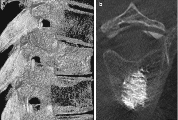
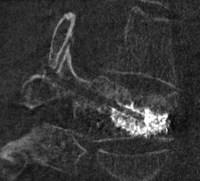

Fig. 12.4
(a) A sagittal section through the 3D stack obtained from DynaCT (Siemens Medical Solutions, Erlangen, Germany). Note the degree of osteoporosis in the upper and the lower vertebral body surrounding the one with bone cement. (b) An axial section through the vertebral body showing the distribution of bone cement

Fig. 12.5
An oblique section through the 3D stack obtained from DynaCT (Siemens Medical Solutions, Erlangen, Germany). Note the access track and the degree of osteoporotic compression fracture in the vertebral body
Other Procedures
Integrated scanning modes that combine R&F, angiography, and CT may also be useful in other interventional procedures such as TIPS and chemoembolization of tumors. Performance of percutaneous biopsy will also be enhanced by this technique. While many interventional procedures can be easily performed in a plain fluoroscopic mode, the integrated mode provides additional flexibility: in those patients where cross-sectional imaging is necessary, it will be available intraoperatively. Potentially, with the omniscanning systems currently being developed, a procedure could start in conventional fluoroscopic mode and, if necessary, switch to CT.
Current Limitations and Future Directions
Currently the projection data has to be transferred from one computer system to another for 3D reconstruction. This is less than ideal. A new software environment needs to be developed that allows angiography, fluoroscopy, and ultrahigh-resolution CT scanning in a unified user interface. Using this interface, one can seamlessly interchange from one mode to another without moving the patient.
Ultrahigh-Resolution Flat-Panel CT
Digital flat-panel-based volume CT (fpVCT) represents a variation of the C-arm-based CT concept described earlier. In these, scanners use a standard CT gantry capable of continuous rotation by virtue of its slip rings. The usual arc of detector rows is replaced by a flat-panel detector to enable cone-beam CT in a standard setup. Because of the stability of the gantry and its ability to acquire data continuously as it rotates around the patient, this unique design is capable of ultrahigh spatial resolution and dynamic CT scanning [16].
This innovation, when fully developed, has the promise of opening a unique window on human anatomy and physiology. For example, one can directly visualize the trabecular structure of bone using fpVCT, enabling assessment of trabecular architecture [17]. It is possible to tomographically observe the perfusion of an organ (e.g., after transplant or an ischemic event). Our early ex vivo experiments have shown the ability of fpVCT to assess diverse phenomena such as microcirculation of cardiac muscle, internal composition of vulnerable plaque, stone fragmentation after lithotripsy, hairline fractures through carpal bones, integrity of middle ear prostheses, and placement of individual electrodes of a cochlear implant.
Stay updated, free articles. Join our Telegram channel

Full access? Get Clinical Tree


