and John P. Deveikis2
(1)
Department of Surgery, Division of Neurosurgery, and Departments of Radiology and Neurology, University of Alabama, Birmingham, AL, USA
(2)
Bayfront Medical Center, St. Petersburg, FL, USA
Abstract
Catheter angiography is still considered the gold standard for imaging cerebral vasculature. Diagnostic angiography is also typically done as the first step during neurointerventional procedures. Mastery of diagnostic angiography is a prerequisite for neurointerventional training. Training standards formulated by the American Society of Interventional and Therapeutic Neuroradiology (ASITN), the Joint Section of Cerebrovascular Neurosurgery, and the American Society of Neuroradiology (ASNR) recommend the performance of at least 100 diagnostic angiograms before entering neuroendovascular training. This handbook authors’ preference, however, is for a neurointerventionalist-in-training to perform at least 250 diagnostic cerebral angiograms prior to becoming the lead operator in neurointerventional cases.
Catheter angiography is still considered the gold standard for imaging cerebral vasculature. Diagnostic angiography is also typically done as the first step during neurointerventional procedures. Mastery of diagnostic angiography is a prerequisite for neurointerventional training. Training standards formulated by the American Society of Interventional and Therapeutic Neuroradiology (ASITN), the Joint Section of Cerebrovascular Neurosurgery, and the American Society of Neuroradiology (ASNR) recommend the performance of at least 100 diagnostic angiograms before entering neuroendovascular training.1 This handbook authors’ preference, however, is for a neurointerventionalist-in-training to perform at least 250 diagnostic cerebral angiograms prior to becoming the lead operator in neurointerventional cases.
2.1 Indications
1.
Diagnosis of primary neurovascular disease (e.g., intracranial aneurysms, arteriovenous malformations, dural arteriovenous fistulas, atherosclerotic stenosis, vasculopathy, cerebral vasospasm, acute ischemic stroke)
2.
Planning for neurointerventional procedures
3.
Intra-operative assistance with aneurysm surgery
4.
Follow-up imaging after treatment (e.g., after aneurysm coiling or clipping, treatment of arteriovenous fistulas)
2.2 A Brief History of Cerebral Angiography
The first report of X-ray angiography of blood vessels was in 1896. In Vienna, E. Haschek and O.T. Lindenthal obtained x-rays of blood vessels by injecting a mixture of petroleum, quicklime, and mercuric sulfide into the hand of a cadaver.2 António de Egas Moniz, a Portuguese neurologist, is credited with the introduction of cerebral angiography. Moniz was interested in developing “arterial encephalography” as a means to localize brain tumors. He obtained cerebral angiograms in cadavers using a solution of strontium bromide and sodium iodide. These early studies demonstrated universal branching patterns among the intracranial arteries, which were contrary to popular theories based on cadaver dissection. After studies in dogs and monkeys, Moniz and his pupil Almeida Lima, performed the first angiogram on living human patients in 1927.3 The initial attempts were done using percutaneous injections of strontium bromide failed to show any opacified vessels.4 In later attempts, cervical internal carotid artery was surgically exposed and temporarily occluded with a ligature while a total of 5 mL of a solution of 25% sodium iodide was injected into the vessel. Flow was restored in the artery while simultaneously obtaining an X-ray. After the ninth attempt, successful visualization of the vessels was obtained. Monitz reportedly declared: “Nous avons realise notre desideratum.” 4 (Very loosely translated: “Now that’s what I needed.”) Although no complications were noted during the procedure, one patient died 2 days later in status epilepticus.5 Moniz went on to obtain successful angiograms in other patients with epilepsy, brain tumors, and postencephalitic Parkinsonism.6,7 The first cerebral venogram was accomplished in 1931 when an inadvertent delay in photographing an angiographic plate led to an image of the venous angiographic phase, which Moniz termed a “cerebral phlebogram.”
The technique became fully developed in the 1930s. By then, cerebral angiography involved direct percutaneous puncture of the carotid artery and injection of iodinated organic contrast media.8 Despite a flurry of publications about cerebral angiography over the ensuing decade, many by Moniz himself, ventriculography and encephalography remained more popular as methods to image intracranial pathology.9 Moniz was awarded the Nobel Prize in Physiology and Medicine in 1949 for his work on frontal leukotomy for psychiatric disorders, which, unlike cerebral angiography, gained early and widespread acceptance by the medical community.10 The popularity of cerebral angiography did rise significantly by the 1950s, becoming the premier method to image the intracranial space. The neurosurgeon Gazi Yasargil performed some 10,000 angiograms between 1953 and 1964.9
Direct percutaneous puncture of the cervical carotid artery remained the primary technique for cerebral angiography in the 1950s and 1960s. Direct puncture of the vertebral artery was reported in 1956;11 the posterior circulation was also imaged by puncture of the right brachial artery and retrograde injection of the contrast into the vertebral artery.12,13 The movie The Exorcist (1973) featured a graphic (and realistic) depiction of a direct carotid stick. The transition from direct puncture of the cervical vessels to transfemoral artery arteriography began in the late 1960s14 and became widespread in the 1970s.
The introduction of computed tomography (CT) in the early 1970s sharply reduced the demand for diagnostic angiography, although the field continued to develop because of the advent of interventional cardiology and other interventional fields. Metrizamide, introduced in the 1970s, was the first nonionic isosmolar iodinated contrast medium. Nonionic contrast media improved the safety and comfort of angiographic procedures considerably.
Digital subtraction angiography (DSA) was introduced in the 1980s as a method for intravenous injection of contrast for imaging the arterial system, as the contrast in the arterial system following intravenous injection was too dilute to be imaged with standard X-rays. Over the ensuing decade, the spatial resolution of DSA imaging improved to the extent that it began to rival the resolution of unsubtracted X-ray images. Further technical refinements in recent years include rotational angiography, 3D angiography, and flat panel detectors for imaging.
2.2.1 Global Gem
Europe was the cradle of cerebral angiography. After Moniz introduced cerebral angiography in Portugal, numerous other Old World pioneers contributed to the early development of the technique, including Herbert Olivecrona, Erik Lysholm, Georg Schönander, and Sven-Ivar Seldinger (Sweden); Norman Dott (Scotland); Arne Torkildsen (Norway); Sigurd Wende (Germany); Fedor Serbinenko (Russia); Georg Salamon and René Djindjian (France); and George Ziedses des Plantes (the Netherlands).
2.3 Complications of Diagnostic Cerebral Angiography
Informed consent prior to an angiogram should include an estimate of the risk of complications.
2.3.1 Neurological Complications
Neurological complications in cerebral angiography are most commonly cerebral ischemic events that occur as a result of thromboembolism or air emboli from catheters and wires. Other causes include disruption of atherosclerotic plaques and vessel dissection. Less common neurological complications include transient cortical blindness15,16 and amnesia.17
In a prospective analysis of 2,899 diagnostic cerebral angiograms, the largest recent series published to date, Willinsky and colleagues reported an overall rate of neurological complications of 1.3%.18 Of these, 0.9% were transient or reversible, and 0.5% were permanent. The Asymptomatic Carotid Atherosclerosis Study (ACAS) reported an often quoted neurological complication rate of 1.2% with angiography.19
The risk of complications appears to be related to the underlying disease process. Patients with atherosclerotic carotid disease have been reported to be at elevated risk of neurological complications with cerebral angiography.20 Other risk factors for neurological complications include a recent cerebral ischemic event,21,22 advanced age,18,20 a long angiography procedure time,20,23,24 and a diagnosis of hypertension,24 diabetes24 or renal insufficiency.25
The risk of neurological complications in patients with subarachnoid hemorrhage, intracranial aneurysms, and arteriovenous malformations was found to be relatively low in a meta-analysis of prospective studies of angiography.22 For these patients, the overall rate of neurological complications was 0.8%, and the rate of permanent neurological complications was 0.07%. The Joint Standards of Practice Task Force of the Society of Interventional Radiology, the American Society of Interventional and Therapeutic Neuroradiology, and the American Society of Neuroradiology reviewed the complications reported in clinical series and produced guidelines for expected complication rates in neuroangiography (Table 2.1).26 The figures in these guidelines can be quoted to patients during informed consent.
Table 2.1
Quality improvement guidelines for adult diagnostic neuroangiography
Suggested complication – specific threshold (%) | ||
|---|---|---|
Neurological complications | Reversible neurologic deficit | 2.5 |
Permanent neurologic deficit | 1 | |
Non-neurologic complications | Renal failure | 0.2 |
Arterial occlusion requiring surgical thrombectomy or thrombolysis | 0.2 | |
Arteriovenous fistula/pseudoaneurysm | 0.2 | |
Hematoma requiring transfusion or surgical evacuation | 0.5 | |
All major complications | 2 |
2.3.2 Nonneurological Complications
Nonneurological complications of cerebral angiography via the femoral artery include groin and retroperitoneal hematoma, allergic reactions, femoral artery pseudoaneurysm, thromboembolism of the lower extremity, nephropathy, and pulmonary embolism.27 In a review of 2,899 cerebral angiograms, hematomas occurred in 0.4% of procedures, allergic cutaneous reactions occurred in 0.1%, and a pseudoaneurysm occurred after one (0.03%) procedure.18
2.4 Cerebral Angiography: Basic Concepts
2.4.1 Preprocedure Evaluation
1.
A brief neurological exam must be conducted to establish a baseline, should a neurologic change occur during or after the procedure.
2.
The patient should be asked if he or she has had a history of iodinated contrast reactions.
3.
The femoral pulse, as well as the dorsalis pedis and posterior tibialis pulses, should be examined.
4.
Blood work, including a serum creatinine level and coagulation parameters, should be reviewed.
2.4.2 Pre-angiogram Orders
1.
NPO except medications for 6 h prior to the procedure.
2.
Place 1 peripheral IV (2 if an intervention is anticipated).
3.
Place foley catheter (only if an intervention is anticipated).
2.4.3 Contrast Agents
Nonionic contrast agents are safer and less allergenic than ionic preparations.28–31 Iohexol (Omnipaque®, GE Healthcare, Princeton, NJ), a low osmolality, nonionic contrast agent, is relatively inexpensive and probably the most commonly used agent in cerebral angiography.
1.
Diagnostic angiogram: Omnipaque®, 300 mg I/mL
2.
Neurointerventional procedure: Omnipaque®, 240 mg I/mL
Patients with normal renal function can tolerate as much as 400–800 mL of Omnipaque®, 300 mg I/mL without adverse effects.32
2.4.4 Femoral Artery Sheath (vs. No Sheath)
Trans-femoral angiography can be done with or without a sheath.
2.4.4.1 Sheath
1.
Allows for the rapid exchange of catheters and less potential for trauma to the arteriotomy site.
2.
Shown in a randomized trial to lessen the frequency of intraprocedural bleeding at the puncture site, and to ease catheter manipulation.33
3.
Short sheath (10–13-cm arterial sheath) is used most commonly.
4.
Longer sheath (25 cm) is useful when ileofemoral artery tortuosity or atherosclerosis might impair catheter navigation.
5.
Technique: A 5F sheath (Check-Flo® Performer® Introducer set; Cook, Bloomington, IN) is slowly and continuously perfused with heparinized saline (10,000 U heparin per liter of saline) under arterial pressure.
6.
Sheaths come in sizes 4F up to 10F or larger. The size refers to the inner diameter. The outer diameter is 1.5–2.0F larger than the stated size.
2.4.4.2 No Sheath
1.
Slightly smaller arteriotomy and permitting earlier ambulation.
3.
Technique: After the Potts needle enters the femoral artery, a 145 cm 0.035 in. J-tipped wire (for most 4F catheters) or a 145 cm 0.038 in. J-tipped wire (for most 5F catheters) is introduced instead of a short J-wire. The Potts needle is then exchanged for an appropriately sized dilator, which is then exchanged for the diagnostic catheter.
4.
Note: If a 4F or smaller catheter is going to be used without a sheath, use an appropriately sized micropuncture set, because a standard 18 gauge Potts needle creates an arteriotomy larger than the catheter, resulting in bleeding around the catheter.
2.4.5 Sedation/Analgesia
1.
Midazolam (Versed®) 1–2 mg IV for sedation; lasts approximately 2 h
2.
Fentanyl (Sublimaze®) 25–50 μg IV for analgesia; lasts 20–30 min
The use of sedation should be minimized, as over-sedation makes it hard to detect subtle neurological changes during the procedure. Paradoxical agitation has been reported in up to 10.2% of patients35, particularly elderly patients and patients with a history of alcohol abuse or psychological problems.36 Flumazenil (Romazicon®) 0.2–0.3 mg IV can reverse this effect.37
2.4.6 Suggested Wires and Catheters for Diagnostic Cerebral Angiography
2.4.6.1 Hydrophilic Wires
1.
The 0.035 in. angled Glidewire® (Terumo Medical, Somerset, NJ) is soft, flexible, and steerable.
2.
The 0.038 in. angled Glidewire® (Terumo Medical, Somerset, NJ) is slightly stiffer than the 0.035 in., making it helpful when added wire support is needed.
3.
Extra-stiff versions of these wires are available for even more support, but they should be used with extreme caution because of the tendency of the tip to dissect vessels.
2.4.6.2 Catheters
Many catheters are suitable for cerebral angiography (Fig. 2.1). As a general rule, use 100 cm long catheters that have a curve that allows selection of the vessels from the arch. Simpler curves (e.g. Berenstein curve) are adaptable to many anatomic situations and are most appropriate for young patients with straighter vessels. More complicated curves (e.g. Simmons curve) help deal with more difficult aortic arch anatomy.
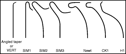

Fig. 2.1
Recommended diagnostic catheters: 5F Angled Taper, Good all-purpose diagnostic catheter. 4 or 5F Vertebral, Good all-purpose diagnostic catheter, slightly stiffer than the Angled Taper but similar in shape. 4 or 5F Simmons 1, Spinal angiography. 4 or 5F Simmons 2 or 3, Left common carotid artery; bovine configuration; tortuous aortic arch; patient’s age > 50. 5F CK-1 (aka HN-5), Left common carotid or right vertebral artery. 5F H1 (aka Headhunter), Right subclavian artery; right vertebral artery. 4 or 5F Newton, Tortuous anatomy, patients >65.
Measurement systems |
|---|
Needles: Gauge, which is a measurement system too obscure for the human mind to grasp. The larger the gauge, the smaller the needle |
Catheters: French (F), defined as the outer diameter of a catheter measured as a multiple of thirds of a millimeter (French number/3 = outer diameter in mm) |
Wires: Measured in thousandths of an inch. (a 0.035 wire is 0.035 in. thick) |
2.4.6.2.1 Global Gem! The French System
The French system comes from Joseph-Frédéric-Benoît Charrière, a nineteenth-century Parisian maker of surgical instruments.38 A urinary catheter 5 mm in diameter was made by rolling a 15 mm wide strip of rubber into a tube. The diameter (circumference/π, or ∼15 mm/3.14) was roughly equal to three times the width of the strip plus the glue to hold it together. The incomprehensible gauge system was developed by the British.
2.5 Catheter Navigation
Diagnostic catheters should usually be advanced over a hydrophilic wire. The wire keeps the catheter tip from rubbing against the wall of the vessel and causing a dissection. When advancing the wire and catheter toward the aortic arch from the femoral artery, the tip of the wire should be followed by direct fluoroscopic visualization. The catheter/wire assembly should never be advanced with <8–10 cm of wire extending from the tip, as a short length of leading wire can act as a spear and cause injury to the intima. A catheter/wire assembly with only a few cm of wire sticking out can resemble a Roman short sword (Fig. 2.2).
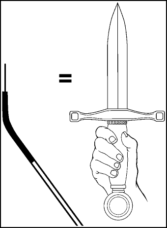

Fig. 2.2
Roman short sword.
2.6 Roadmapping
Roadmapping should be used when engaging the vertebral arteries, and the internal and external carotid arteries. Roadmapping is essential during intracranial navigation. In some angiography suites, a “false roadmap” can be created using a regular digital subtraction angiogram; a frame from an angiographic run is selected, then inverted (i.e., vessels are turned white against a black background). This technique conserves contrast and reduces radiation exposure.
2.7 Double Flushing
Double flushing consists of aspiration of the contents of the catheter with one 10-mL syringe of heparinized saline, followed by partial aspiration and irrigation with a second syringe of saline. This maneuver clears clots and air bubbles from the catheter, and should be done every time a wire is removed from the catheter, prior to the injection of contrast. Meticulous attention to detail is required to prevent blood from sitting in the catheter lumen, where it can coagulate into potential emboli. Any air bubbles in the system can also occlude small vessels if injected intravascularly.
2.8 Continuous Saline Infusion
A three-way stopcock or manifold can be used to provide a heparinized saline drip through the catheter. This continuous drip is particularly useful if there is any delay between injections of contrast, because it keeps the catheter lumen free of blood products. Careful double flushing is still required if a wire is inserted and removed or if any blood is present in the lumen. Use of stopcocks and continuous infusion is mandatory for any therapeutic intervention.
2.9 Hand Injection
A 10-mL syringe containing contrast should be attached to the catheter, and the syringe should be snapped with the middle finger several times to release bubbles stuck to the inside surface. The syringe should be held in a vertical position, with the plunger directed upward, to allow bubbles to rise away from the catheter (Fig. 2.3). For larger vessels, like the common carotid artery, the plunger on the syringe can be depressed with the palm of the hand in order to generate enough force; for smaller vessels, like the vertebral arteries, thumb-depression of the plunger is sufficient. An adequate angiographic run can be done with a single swift injection of 4–6 mL of contrast (70%) mixed with saline (30%). The patient should be instructed to stop breathing (“Don’t move, don’t breath, don’t swallow”) for several seconds during the angiogram, then told to start breathing again.
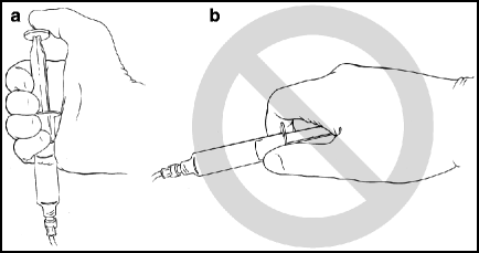

Fig. 2.3
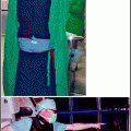
Syringe holding method for hand injections. Correct method (a): the syringe is grasped in the palm of the hand when it is attached to the catheter; this position places the plunger in an upright position to allow bubbles to rise away from the attachment to the catheter. Incorrect method (b): the syringe is held in a horizontal position, like a weapon. Bubbles can go any which way.
A Poetic Interlude
Bubbles
I love ‘em in my lager.
I love ‘em in my stout.
But when they get inside my head
I want to get them out!
I hate them in carotids.
I hate them in the “verts.”
They end up doing something bad.
Oh yes, it really hurts!
The small ones make me stupid.
The big ones make me dead.
‘Cause when they get inside me
They dance around my head!
The little doctors search and search
And shake out all they find.
The ones they missed
(It makes me pissed!)
Will make me lose my mind!
They find them in my saline.
They find them everywhere!
And superficial temporal ones
Will make me lose my hair!
2.9.1 Prevention of Cerebral Air Emboli
Use meticulous technique for flushing and contrast injections (see above).
Whenever possible, flush the catheter in the descending aorta to keep bubbles away from the cerebral circulation.
After filling a syringe, allowing it to sit for a few minutes before injection will allow bubbles to come out of suspension and become visible.39
A slower flush is less likely to cause bubbles than a rapid flush.39
1.2 μm Intrapur® filter (B. Braun Medical, Bethlehem, PA) or Posidyne® filter (Pall Medical, Port Washington, NY) in the tubing for contrast or saline injections can reduce the risk of air emboli.40
2.9.2 Management of Cerebral Air Emboli
Prevention is best, but if air emboli are suspected, urgent treatment is required to prevent stroke caused by occlusion of flow in vessels due to the surface tension produced by the interface between air and blood.
If the gas embolus is large enough to be detected fluoroscopically, and the vessel is easily accessible, a microcatheter may be used to aspirate the gas embolus and flush the vessel with heparinized saline to break up the remaining bubbles.
Quick and readily available (though unproven) methods include the use of transcranial Doppler (to agitate and break up bubbles), heparinization (to prevent clot from forming in vessels stagnating from the air), and administration of oxygen and induction of hypertension (as in vasospasm therapy).
If available, hyperbaric oxygen chambers have been shown (anecdotally and in small series) to result in good outcomes.41–44 One report indicated a benefit even after a delay in initiated hyperbaric therapy.45
However, a larger series showed 67% good outcome when hyperbaric treatment was started within 6 h after the onset of symptoms, versus only 35% good outcomes when treatment began later.46
Induction of retrograde cerebral flow by infusing arterial blood under pressure in the jugular vein has been shown to limit ischemic damage to the brain.47
When in doubt, a variety of methods can be used simultaneously, including hyperbaric oxygen plus retrograde cerebral flow plus induction of barbiturate coma to attempt to protect the brain.48
The most important thing is to recognize that air emboli have occurred and then use whatever treatment modalities that are available.
2.10 Mechanical Injection
A power contrast injector is necessary for aortic arch angiograms, and some operators prefer to use an injector routinely for other vessels as well. Mechanical injection can lower radiation exposure to the operator’s hands and body.49 The pressure (pounds per square inch, psi) and flow rate during the injection should not exceed the rated pressure or flow rate of the catheter. Likewise, if a stopcock is used, the psi during injection should not exceed the rated pressure and flow rate. Common power injector settings for selective catheter digital subtraction diagnostic angiograms using a 5F catheter are listed in Table 2.2. The term “rate rise” refers to a setting on the mechanical injector that causes it to gradually increase the rate of contrast flow during the injection, to prevent the catheter tip from being kicked out of the vessel it is in. Rate rise is defined as the time required during the injection to reach the maximum flow rate. If the vessel is smaller than average, occluded, or if the catheter is in an unstable position within the vessel, a rate rise of 0.3–0.5 s should be used. Power injector settings are different (longer) when a 3D angiogram is done; typical settings for 3D images are 3 mL/s, total of 18 mL or 4 mL/s; total of 24 mL.
Table 2.2
Standard power injector settings
Vessel | Power injector settings |
|---|---|
Aortic arch | 20 mL/s; total of 25 mL |
Common carotid artery | 8 mL/s; total of 12 mL |
Subclavian artery | 6 mL/s; total of 15 mL |
Internal carotid artery | 6 mL/s; total of 8 mL |
External carotid artery | 3 mL/s; total of 6 mL |
Vertebral artery | 6 mL/s; total of 8 mL |
2.11 Vessel Selection
A cerebral angiogram should begin with the vessel of interest first, so that the most important vessels can be imaged in case problems with the equipment or the patient prevent completion of the entire angiogram. Following catheterization of the vessel of interest, it is usually easiest to navigate from right to left (i.e., the right vertebral artery, followed by the right common carotid artery, etc.).
2.11.1 Angiographic Images and Standard Views
1)
Biplane angiography is the standard of care for cerebral angiography. It allows for orthogonal images to be simultaneously obtained with a single contrast injection, limiting the time and amount of contrast needed to adequately visualize the cerebral vasculature. Monoplanar cerebral angiography is acceptable only when biplane equipment is not available; the use of monoplane imaging is limited by its inability to perform automatic optical calibration and to image from orthogonal views simultaneously.
2)
When viewing the angiographic images, the contrast and brightness of the image should be adjusted so that vessels are semitransparent; this can allow visualization of aneurysms, branches, or filling defects (e.g., intraluminal thrombus), which may otherwise not be visible.
3)
Other imaging features worthy of attention during the performance of a cerebral angiogram:
a)
Vessel contour and size (“angioarchitecture”)
b)
Contrast flow patterns
c)
Presence or absence of a vascular blush
d)
Venous phase (i.e., do not forget to examine the venous phase)
e)
Bony anatomy
Standard skull views are illustrated in Fig. 2.4. The “standard” postero-anterior (PA) projection angulates the X-ray tube usually 15–20° in a cranial direction to superimpose the roof of the orbits and top of the petrous ridges. This has been the traditional angiographic view for the carotid injections since it gives good overview of the arterial structures and allows a standard projection regardless of how much the patient’s head is angulated on the table. A straight PA view may place the petrous ridges at variable relationships with the roof of the orbits, with resultant variable appearance of the intracranial vessels depending on how the patient is positioned. This view is frequently used since it requires no angulation of the X-ray C-arm. The Caldwell projection is usually done with approximately 25° caudal angulation of the X-ray tube. It aligns the petrous ridges with the bottom third of the orbits to provide a view of orbital and supratentorial structures unobstructed by the petrous ridges. The Towne’s view, with 30–40° cranial angulation aligns the petrous ridges below the superior rim of the orbits and is the standard PA view for imaging the posterior fossa, since it elongates the posterior cerebral arteries. The patient can be asked to tuck his or her chin to the chest to optimize the cranial angulation. The Water’s view is inclined 45° caudal and positions the petrous ridges some distance below the orbits; this is a good view for imaging the maxillary sinuses, and is an excellent view to show the full length of the basilar artery. Sub-mentovertex (aka basal or axial) view requires very steep caudal angulation such that the image intensifier is often touching the patient’s chest. It helps to tilt the patient’s head back to obtain this view. This is a very useful view for the middle cerebral bifurcation and Acomm. Lateral views should line up the floor of the anterior fossa and external auditory canals bilaterally to ensure a true lateral view.
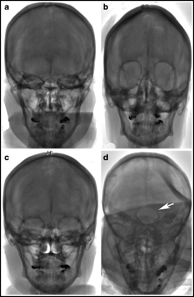
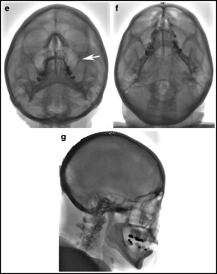


Fig. 2.4
Standard PA and lateral projections. (a) Standard PA. The petrous bones line up with the upper margin of the orbits. Elderly angiographers prefer this traditional view for intracranial anterior circulation angiography. (b) Straight PA. No cranial, or caudal angulation is done. In this case, the petrous bones are at the lower edge of the orbits. Younger angiographers prefer this view to the “standard PA” view. (c) Caldwell. 25° caudal angulation. The petrous bones are about one third of the way up the orbits. (d) Towne. 35° cranial angulation. The foramen magnum (arrow) can be seen through the calvarium. (e) Water. The view is from below with 45° caudal angulation; the maxillary sinuses (arrow) can be seen clearly. (f) Submentovertex. The view is from way below, with as much caudal angulation as possible; the vertex of the skull should be framed by the mandible. (g) Lateral. On a straight lateral view, the floor of the left and right anterior fossa directly overlap.
The Haughton projection is a lateral view and is helpful for imaging the carotid siphon and the middle cerebral bifurcation (Fig. 2.5). The patient’s head is inclined away from the side of the injected carotid artery;50 this view opens up the carotid siphon. Specific views commonly used to optimize display of certain anatomic structures are listed in Table 2.3. All of these views should be done with tight collimation of the X-ray source over the area of interest to limit scatter radiation and with the imaging detector as close to the head as possible to minimize image degradation from geometric magnification.
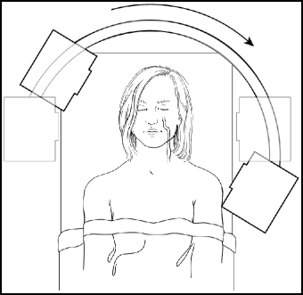

Fig. 2.5
Haughton view for imaging the left carotid siphon and MCA candelabra. The carotid siphon and MCA candelabra can often be seen most clearly by positioning the lateral arc as if the patient’s head is tilted away from the side of injection. A mnemonic to remember this is: “The X-ray tube should touch the shoulder on the side of interest”.
Table 2.3
Standard views
Target | Optimal views | Additional views/comments |
|---|---|---|
Carotid bifurcation | Standard PA | Ipsilateral oblique |
Lateral | ||
Anterior intracranial circulation | Standard PA | |
Lateral | ||
ICA cavernous segment | Caldwell | Haughton |
Lateral | ||
ICA ophthalmic segment | Caldwell | Transorbital oblique |
Lateral | ||
Posterior communicating artery aneurysms | Haughton | Lateral |
Transorbital oblique | ||
ICA bifurcation | Transorbital oblique | |
Anterior communicating artery aneurysms | Transorbital oblique | Sometimes submentovertex |
Middle cerebral artery aneurysms | Transorbital oblique | |
Submentovertex | ||
Middle cerebral artery candelabra | Lateral with Haughton | |
Waters with oblique | ||
Vertebral artery origin | Towne | The vertebral artery arises from the posterior aspect of the subclavian artery |
Posterior circulation | Water | Ipsilateral oblique |
Lateral | ||
Basilar artery | Water | Ipsilateral oblique |
Lateral | Water will “elongate” the basilar artery trunk | |
PCA, SCA, AICA, PICA | Towne | Towne elongates PCA. Ipsilateral oblique helps |
Lateral | Caveat: Paired vessels overlap | |
Basilar apex aneurysms | Water | Ipsilateral oblique |
Lateral |
2.11.1.1 Pearl
Mnemonic for remembering the relative positions of the standard PA projections: The Water(s) runs beneath the Town(e). Caldwell is in between.
2.11.2 Frame Rates for Digital Subtraction Angiography
Most cerebral angiography can be done with 3–5 fps. Higher rates (e.g., 8–20 fps) are useful for imaging arteriovenous malformations and other high-flow lesions. Usually, a variable frame rate may be used to limit radiation dose, since a higher frame rate (3/s) is needed in the arterial phase, whereas a lower rate (0.5–1/s) can be used in the venous phase. For standard cerebral arteriography, a 10–12 s imaging sequence allows for visualization of arterial, capillary, and venous phases.
2.11.3 Calibration and Measurement
Biplanar angiography units are capable of auto-calibration by analysis of simultaneous orthogonal images. Monoplanar angiography requires placement of a marker on or in the patient. A United States dime is 18 mm in diameter and can be taped to the patient’s face or head; however a marker on the surface of the patient’s body can be inaccurate in the measurement of internal structures because of magnification. Magnification error can lead to errors in linear measurement of up to 13%.51 Markers on intravascular catheters and wires, placed close to the angiographic target, are more accurate. The ATW™ Marker Wire (Cordis, Miami Lakes, FL) has radio-opaque markers that are 1-mm wide and spaced 10 mm apart. “Two-tipped” microcatheters for detachable coil deployment have markers that are spaced 3 cm apart. To maximize accuracy, the calibration marker and the structure being measured should be as close to the center of the image as possible to minimize the effect of X-ray beam divergence.
2.12 Procedures
2.12.1 Femoral Artery Puncture
1)
Prepare and drape the groin area.
2)
Palpate the femoral pulse at the inguinal crease, and infiltrate local anesthesia (2% lidocaine), first by raising a wheal and then injecting deeply toward the artery.
Caveat: Do not inject anesthesia too laterally: Injecting directly in the nerve can cause a femoral neuropathy that persists for hours.
3)
Make a 5 mm incision parallel to the inguinal crease with an 11-blade scalpel.
4)
Insert a Potts needle with the bevel facing upward. Advance it at a 45° angle to the skin, pointing toward the patient’s opposite shoulder.
5)
Attempt a single-wall puncture especially if heparin or antiplatelet agents are used. Do it by looking for blood return from the hollow stylet of the Potts needle. Advance the needle 1–2 mm after the first blood return since the stylet protrudes that far beyond the tip of the needle.
6)
Make a two-wall puncture by advancing the needle through-and-through both vessel walls, remove the stylet, and slowly withdraw the needle until pulsatile blood return is obtained.
7)
When bright red, pulsatile arterial blood is encountered, gently advance a J-wire through the needle for 8–10 cm.
8)
Exchange the needle for a 5F sheath, and secured it with a silk stitch.
2.12.1.1 Pearls
If the artery is difficult to locate, try the following tricks:
After inserting the Potts needle, let go of it. If the needle pulsates medially or laterally, the artery is usually located to the side that the needle is pulsating toward.
Fluoroscopic bony landmarks. On PA fluoroscopy, the femoral artery is located 1 cm medial to the center of the femoral head (Fig. 2.6).
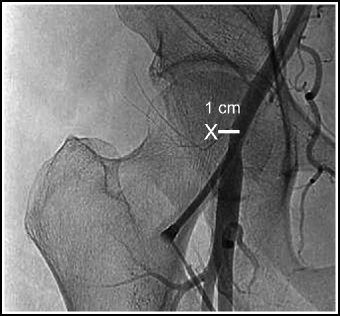
Fig. 2.6
Fluoroscopic landmarks for femoral artery puncture. The femoral artery is located approximately 1 cm medial to the center of the femoral head. The X indicates the center of the femoral head.
Use a micropuncture set (see instructions below). An atherosclerotic femoral artery can be heavily calcified and deflect larger needles; a smaller needle can sometimes be helpful.
Use a needle with a Doppler ultrasound stylet (Smart-needle®, Vascular Solutions, Minneapolis, MN) (20 gauge or smaller) to allow puncture of a non-palpable vessel.
Try the opposite groin or the upper extremity approach.
Puncturing vascular grafts can be difficult due to extensive scar tissue. This may require use of a stiff Amplatz guidewire, use of dilators one size larger than the inserted catheter or sheath, and certain soft catheters should not be used because they may fracture. In general, it is best to use a sheath in Gore Tex® grafts (W.L. Gore, Flagstaff, AZ).
2.12.1.2 Micropuncture Technique
1.
Obtain micropuncture set appropriately sized (4 or 5F).
2.
Insert the 21 gauge needle in same fashion as a Potts needle.
3.
Insert 0.018 in. microwire.
4.
Exchange 21 gauge needle for the dilator.
5.
Exchange dilator for the sheath.
2.12.1.3 The Buffalo Scale for Procedural Blood Loss Estimation*
A Novel Method
A Number One: We’re having fun.
A Number Two: It’s on the shoe.
A Number Three: It’s on your knee.
A Number Four: It’s on the floor.
A Number Five: It’s in the sky.
A Number Six: Can’t be fixed.
A Number Seven: Patient’s going to heaven.
A Number Eight: Call for a crate.
*Developed and validated during the fellowship of one this handbook’s authors.
2.12.2 Aortic Arch Imaging
1)
Guide a 4F or 5F pigtail catheter over a hydrophilic wire into the ascending part of the aortic arch.
2)
Place the image intensifier (II) on low magnification and rotate 30° to the left.
3)
The patient’s head is thus rotated to the left, so that his or her face is facing the II (this position will permit visualization of the cervical vessels).
4)
Use a power injector to administer contrast.
5)
Supplement standard left anterior oblique (LAO) view with a lateral view by rotating the II 30° to the right.
2.12.3 Carotid Artery Catheterization
1)
Advance an angled diagnostic catheter over a hydrophilic wire over the aortic arch to a position proximal to the innominate artery.
2)
Bring back the wire into the catheter, and gently pull the catheter back, with the tip of the catheter facing superiorly, until the innominate artery is engaged. Advance the wire superiorly in the right common carotid artery, followed by the catheter.
3)
To engage the left common carotid artery, pull the catheter gently and slowly out of the innominate artery, with the wire inside the catheter and the tip facing to the patient’s left, until the catheter “clicks” into the left common carotid. Then advance the wire superiorly, followed by the catheter.
4)
For older patients (>50 years), and those with a bovine arch configuration, the Simmons II catheter is helpful for accessing the left common carotid.
5)
If selective internal carotid artery catheterization is planned, first do angiography of the cervical carotid system to check for internal carotid artery stenosis in any patient at risk of atherosclerosis. Catheterization of the internal carotid artery should be done under roadmap guidance.
6)
Turning the patient’s head away from the carotid being catheterized may allow the wire and/or catheter to enter the vessel more easily.
7)
Once the common carotid is catheterized, turning the head away from the side being catheterized facilitates internal carotid catheterization, and turning toward the ipsilateral side facilitates external carotid catheterization.
8)
When the wire or catheter does not advance easily into the vessel of interest, ask the patient to cough. It often bounces the catheter into position.
2.12.4 Vertebral Artery Catheterization
1)
Place an angled diagnostic catheter over a hydrophilic wire and into the subclavian artery. Intermittent “puffing” of contrast will allow identification of the vertebral artery origin.
2)


Make a road map and pass the wire into the vertebral artery until the tip of the wire is in the upper third of the cervical portion of the vessel. Placing the wire relatively high in the vertebral artery provides adequate purchase for advancement of the catheter, will help straighten out any kinks in the artery that may be present near the origin, and will also facilitate smooth passage of the catheter past the entrance of the of artery into the foramen transversarium at C6. The C6 foramen transversarium is where the vertebral artery makes a transition from free-floating to fixed, and is a region at risk for iatrogenic dissection if the catheter is allowed to scrape against the wall of the vessel.
Stay updated, free articles. Join our Telegram channel

Full access? Get Clinical Tree


