Figure 2.1
Transducer placement RUQ: Place the transducer over the patient’s right flank between the mid-axillary and anterior axillary line with the transducer marker directed toward the patient’s head
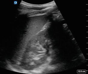
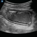
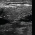
Figure 2.2
RUQ normal EFAST: Normal RUQ EFAST showing no free fluid. Imaging should include the tip of the liver, area between the liver and right kidney, and the diaphragm above the liver
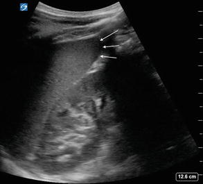
Figure 2.3
EFAST liver tip: RUQ view demonstrating the liver tip above the right kidney. Hemoperitoneum can be detected first around the liver tip; therefore, it is important to image this specific area of the RUQ
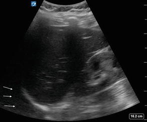
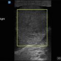
Figure 2.4
RUQ EFAST view with hemithorax: Evaluation of the RUQ should include the right hemithorax, visualized above the liver and hyperechoic diaphragm
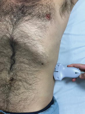
Figure 2.5
Transducer placement LUQ: Place the transducer over the patient’s left flank between the mid-axillary and posterior axillary line near the 10th rib space with the marker pointed toward the patient’s head
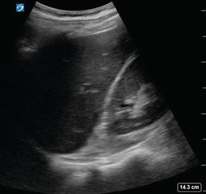
Figure 2.6
LUQ standard view: LUQ EFAST view showing no free fluid. Imaging should include the spleen, area between the spleen and left kidney, and views of the diaphragm above the spleen
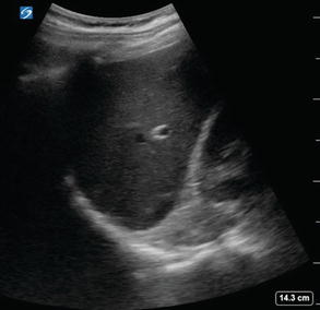
Figure 2.7
LUQ EFAST imaging above the spleen: Free fluid will typically accumulate above the spleen first in the LUQ making it important to always image this area
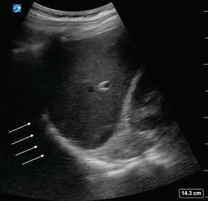
Figure 2.8
LUQ EFAST view with left hemithorax: Evaluation of the LUQ should include the left hemithorax, visualized above the spleen and hyperechoic diaphragm
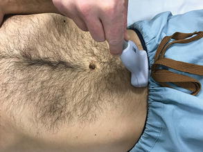
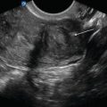
Figure 2.9
Transducer placement pelvis, transverse: Place the transducer superior to the pubic bone angled inferiorly with the transducer marker pointed toward the patient’s right in the transverse plane
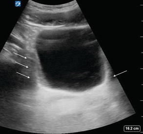
Fig 2.10
Paracolic gutters in transverse: Normal pelvis and bladder EFAST view in a transverse plane. Note bilateral paracolic gutters on each side of the bladder
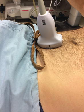
Figure 2.11
Transducer placement bladder in sagittal: From a transverse position, rotate the transducer 90° clockwise to image the pelvis in sagittal plane with the transducer marker pointed to patient’s head
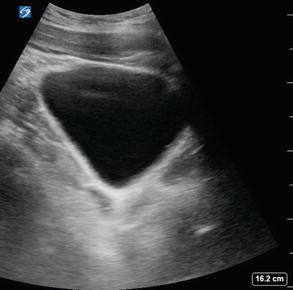
Fig 2.12
Sagittal view of bladder: Normal pelvis and bladder EFAST view in a sagittal plane
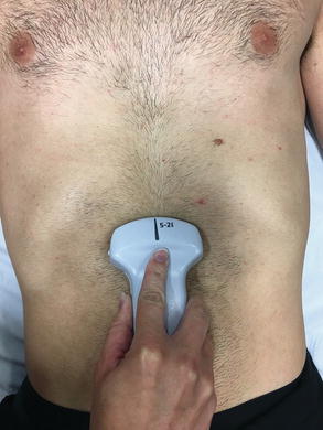
Fig 2.13
Subxiphoid EFAST transducer placement: Place the transducer inferior to the xiphoid process with the marker oriented toward the patient’s right. Place operator’s hand on top of the transducer, use a moderate amount of force to press the transducer into the patient’s abdomen, and angle the transducer superior and leftward toward the left shoulder
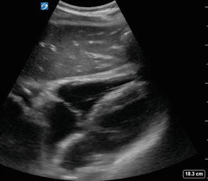
Figure 2.14
Subxiphoid EFAST view: Normal EFAST demonstrating a subxiphoid view of the heart. The liver is used as the acoustic window to view cardiac structures and pericardium. The right heart sits closest to the liver
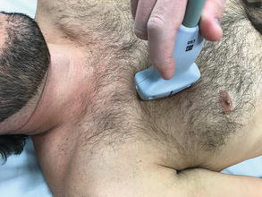
Fig 2.15
Transducer placement lungs: Place the transducer on the anterior chest in a sagittal orientation with the marker pointed toward the patient’s head over the 2nd intercostal space
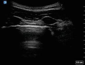
Figure 2.16
Lung view EFAST: Normal EFAST demonstrating lung sliding. Note two anechoic ribs with posterior acoustic shadowing and the hyperechoic pleural line between them
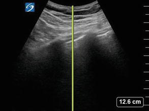
Figure 2.17
M-mode spike position: The M-mode spike should be placed between the two rib shadows overlying the hyperechoic pleural line
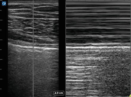
Figure 2.18
Normal sliding lung M-mode: M-mode ultrasonography of a normal lung demonstrates the static chest wall in the top half of image and movement of the lungs in the bottom half consistent with normal respiration. Sometimes referred to as “seashore” sign
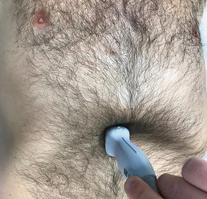
Figure 2.19
Transducer placement IVC: Place the transducer inferior to the xiphoid process, slightly to the right of midline, with the marker oriented toward the patient’s head
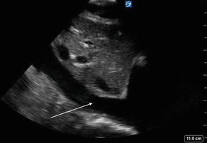
Figure 2.20
IVC view: Normal EFAST view of the IVC as it passes by the liver and drains into the right atrium of the heart
EFAST Pathology
- (a)
Hemoperitoneum
Get Clinical Tree app for offline access
Accumulation of blood within the peritoneum.
Blood will be seen as an anechoic, hypoechoic, or echogenic fluid collection:
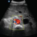
Between the liver and kidney
Figure 2.21—Positive EFAST Morrison’s pouch
Video 2.9—Positive EFAST Morrison’s pouch
Around the liver tip
Figure 2.22—Positive EFAST liver tip
Video 2.10—Positive EFAST liver tip
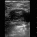
Between the spleen and kidney
Figure 2.23—Positive EFAST LUQ
Video 2.11—Positive EFAST LUQ
Between the spleen and diaphragm
Figure 2.24—Positive EFAST LUQ above the spleenRelated posts:

Stay updated, free articles. Join our Telegram channel

Full access? Get Clinical Tree