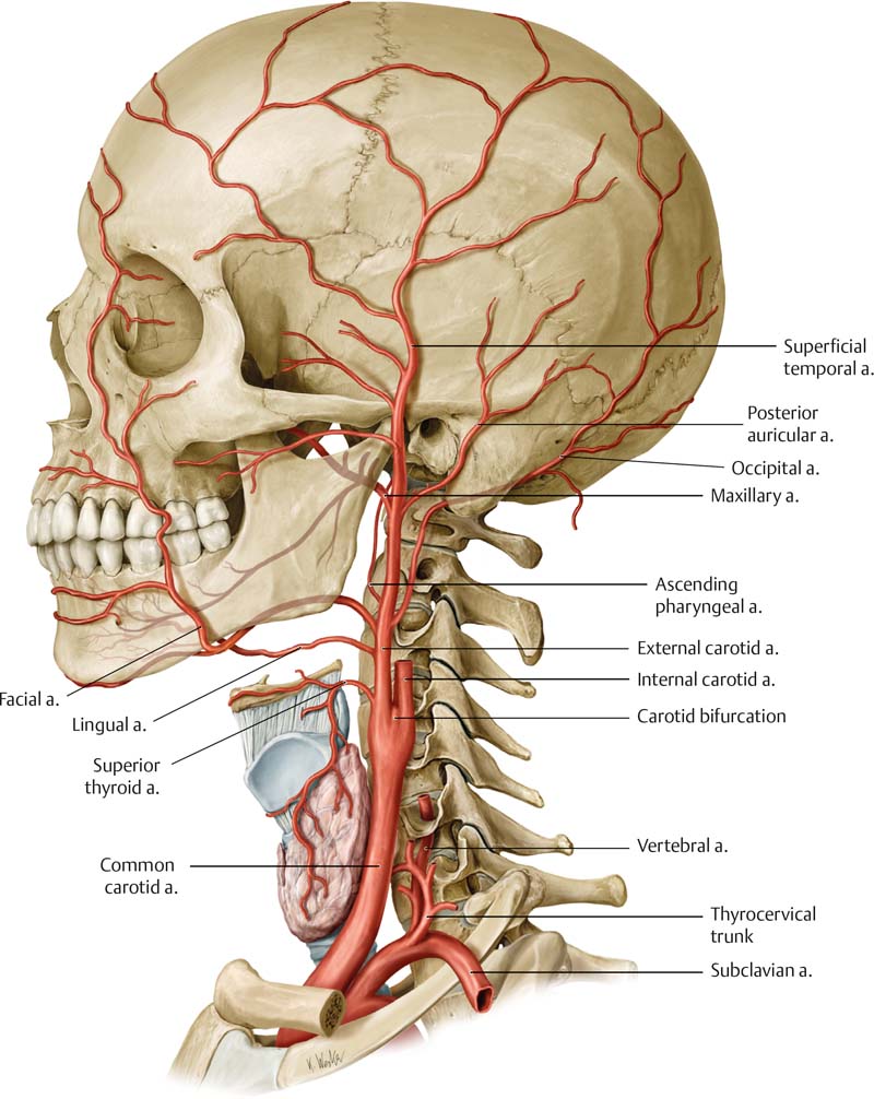
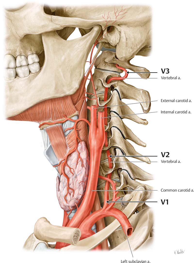
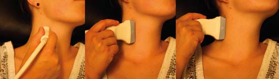
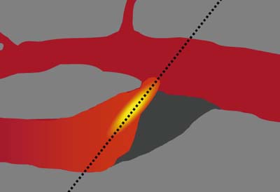
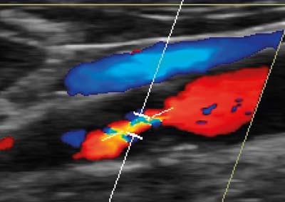
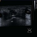
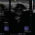
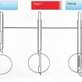
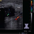
13 Extracranial Vessels Atherosclerotic lesions of the extracranial arteries are responsible for ischemic strokes in many cases. In Germany, approximately 200 000– 300 000 patients suffer from ischemic stroke every year.1 Ultrasonography has become a routine imaging method because it is a precise noninvasive imaging technique for detecting these lesions. The extracranial carotids are superficial and can be detected precisely by ultrasound. Correct imaging techniques and protocols are necessary, however, to avoid misinterpretation of the images. Ultrasonography must be reliable and reproducible, as it is the primary imaging technique that will lead to consequences for treatment. There are many important factors to be considered, such as intimal thickness and intimal structure, plaque morphology, and—last, but not least—the grade of stenosis. The common carotid artery (CCA) will be found anterolaterally in the neck medial to the internal jugular vein. In the carotid sheath there are three main structures: the carotid artery, the internal jugular vein, and the vagal nerve. Up to the carotid bifurcation there are no branches; however, sometimes the superior thyroid originates from the CCA. The CCA divides into two branches, the internal carotid artery (ICA) and the external carotid artery (ECA). The location of the carotid bifurcation is at the height of the fourth vertebral body, but this may vary according to individual anatomical proportions (Fig. 13.1). Differences may be seen between the right and left bifurcation. Fig. 13.1 Lateral view at the carotid bifurcation. The common carotid artery is divided into the external and internal carotid arteries. The external carotid artery is in many cases the smaller of the two terminal branches of the CCA and it continues anteromedial to the ICA in more than 80% of cases. There may be also a lateral course at the bifurcation, which may lead to a more difficult imaging. The division into its major branches varies considerably. In most cases the division into major branches is seen very well by ultrasound with B-mode imaging. The ICA will not demonstrate a comparable division, which is a very valuable distinguishing feature in B-mode images. The internal carotid artery is larger than the ECA and has no cervical branches. There might be some variants in very rare cases. These are persistent fetal anastomoses between the ICA and vertebrobasilar arteries, for example the proatlantal arteries that correspond with the C1 and C2 segmental arteries.2, 3 The ICA can be divided into four major sections: the cervical, petrous, cavernous, and cerebral sections. Only the cervical part can be examined by extracranial ultrasound imaging. The ICA normally exhibits a small bulb at its origin. This is seen as a small dilatation in B-mode imaging. The ICA normally follows the internal jugular vein to the skull. Its course is straight up to the base, but may also vary and demonstrate minor or major elongations, coilings (360°) and even kinks, preferentially in older people with arterial hypertension (Fig. 13.2). The vertebral artery (VA) is the first branch of the subclavian artery (Fig. 13.3). In rare cases its origin is the aortic arch. The VA is divided into four segments: the V1 segment (proximal or ostial segment) from the origin to its entry into the transverse canal at the C6 level; the V2 segment (transversal segment) from its entry into the transverse canal at C6 to the transverse foramen of C2; the V3 segment (suboccipital segment) from the transverse foramen of C2 to its dural penetration at the level of the foramen magnum; and the V4 segment (intracranial segment) from its dural penetration to the vertebrobasilar junction. In 40% of cases the vertebral arteries are not equal in diameter. This asymmetry will be seen on B-mode ultrasound. The VA is described as dominant or minor. There are variations in the course of the VA; the level of entry into the transverse canal is important for ultrasonography. From this point there is discontinuous imaging of the VA due to artifacts of the cervical bones.4 The internal jugular vein (IJV) begins at the base of the skull at the jugular foramen and joins the subclavian vein to form the brachiocephalic vein. It is a large vein with valves ( The position of the patient may be supine or semisupine with the head rotated and hyperextended to the contralateral side of the examiner. The position of the examiner is beside the patient, close to the ultrasound machine, or, alternatively, at the head of the patient. A transducer with a high frequency (at least 7.5 MHz, up to 13 MHz in certain cases) is used to detect the superficial vessels. A high transducer frequency guarantees high-resolution imaging. This is important for plaque imaging methods. In most cases, a linear transducer gives a good visualization of the carotid arteries. In patients with a short neck, a curved-array transducer might be necessary to obtain adequate imaging of the more cranial portions of the ICA. The imaging of the vessel wall is done by high-resolution B-mode imaging. Fig. 13.2 Lateral view at the carotid bifurcation. The internal carotid artery goes straight cranially from the carotid bulb. An elongated course, even with coiling, is possible in the extracranial part. From Atlas of Anatomy, © Thieme 2008; illustration by Karl Wesker. Fig. 13.3 Lateral view at the arteries of the neck. The vertebral artery is divided at the neck into three portions (V1–V3). The longitudinal imaging of the carotid arteries is done in different planes to provide an optimal view of the bifurcation (Fig. 13.4). In many cases there are acoustic shadows that prevent exact visualization of the stenosis using only one plane. Duplex ultrasound combines two-dimensional real-time imaging with Doppler flow analysis to measure blood flow velocities. The method does not directly measure the diameter of the artery or stenotic lesion. Instead, blood flow velocities are used as indicators of the severity of stenosis.6 The orientation of the cervical vessels is optimal in a transverse section. For longitudinal imaging of the cervical vessels there are three standardized longitudinal projections1: positioning of the transducer between the larynx and sternocleidomastoid muscle for sagittal anteroposterior sections2; a lateral approach through the sternocleidomastoid muscle; and a posterolateral approach with the transducer behind the sternocleidomastoid muscle.7 The first step of B-mode imaging is the transverse section and imaging of the vessel wall. The three anatomical layers of the vessel wall (intima, media, and adventitia) are not represented in the B-mode images; B-mode images will not discriminate the intimal layer from the media. Color Doppler imaging of the arterial circulation is used to demonstrate regions of flow disturbances and abnormal blood flow direction. No measurements are made by color analysis. Pulsed-wave (PW) Doppler is used to perform spectral analysis and measurements of blood flow velocities. The examination of both the ECA and the ICA avoids misinterpretation as comparison of the two spectra will improve the discrimination of the vessels at the carotid bifurcation. All flow measurements are performed in a longitudinal section by PW Doppler. Color Doppler demonstrates regions of stenosis by aliasing. These images are helpful for catching the lesion in the PW mode. If there is suspected occlusion of a carotid artery, a colorless lumen will be seen. Color imaging demonstrates coiling and kinking of vessels by a changeover of color. PW Doppler is used for flow velocity measurements. All measurements should be obtained with the best possible angulation. The lower the Doppler angle, the better is the Doppler shift that is achieved. No Doppler shift will be registered with an angle of 90°. The insonation angle should be less than 60° to avoid a critical error in velocity measurements. In many cases angulation below 60° is possible with linear transducers. Especially in patients with a more cranially located bifurcation and a short neck, the insonation angle will be optimized using a curved-array transducer. An insonation angle of 45° is preferred, if possible. The Doppler angle is adjusted to the vector of blood flow, not to the anatomical course of the vessel (Figs. 13.5, 13.6). Exact positioning of the sample volume box is necessary to get the optimal signal. To avoid false high velocities, the sample volume box should not be placed in a curved, nondiseased segment. Fig. 13.4 Position of the transducer during examination in the longitudinal view. Left: the sagittal anteroposterior view with the transducer between the larynx and the sternocleidomastoid muscle. Middle: lateral approach through the sternocleidomastoid muscle. Right: posterolateral view with the transducer behind the sternocleidomastoid muscle. Under normal conditions there is a pulsation of the arteries in B-mode ultrasound. Gentle compression of the neck by the transducer demonstrates a more elliptical shape of the IJV (Fig. 13.7; Intima–media thickness (IMT) of extracranial carotid arteries, measured by B-mode sonography, is considered to be a marker of subclinical atherosclerosis. It is a noninvasive and simple B-mode ultrasound examination that can be done very simply. There is a positive correlation between IMT and well-known risk factors of coronary heart disease (CHD). Carotid IMT is a strong predictor of future vascular events.8 IMT is measured in the far wall of the CCA. If possible, the internal jugular vein is used to achieve better visualization by amplifying the acoustic signal. The transducer is placed perpendicular to the long axis of the vessel wall of the CCA. The leading-edge method is used to obtain thickness measurements (Figs. 13.19, 13.20). The best imaging will be obtained by a high-frequency linear transducer of >10 MHz. Serial IMT measurements should always be performed at the same position, with a distance of ~2 cm to the carotid bifurcation. Only the echogenic layer of the intima and the echo-poor layer of the media are included in the calculation (Figs. 13.21, 13.22, 13.23). Imaging should be frozen during the diastolic cycle. Normal values are between 0.5 and 0.7 mm; critical values are 0.9 mm and above. Fig. 13.5 Demonstration of angle correction. The Doppler angle is applied to the vector of blood velocity, which is demonstrated best with color Doppler mode. The bright color visualizes the direction of blood flow in the stenotic region. Fig. 13.6 Demonstration of angle correction in color-coded duplex sonography. Note the aliasing in the high-grade stenosis, demonstrating a high velocity. The direction of flow is well demonstrated by color mode.
Introduction
Anatomy
 Video 13.1) close to its end and collects many external branches. It is located at the lateral side of the CCA, but anatomical findings demonstrate a variety of locations in relation to the CCA (anterolateral and lateral) and there is a relationship between weight and internal jugular diameter.5
Carotid Arteries
Examination
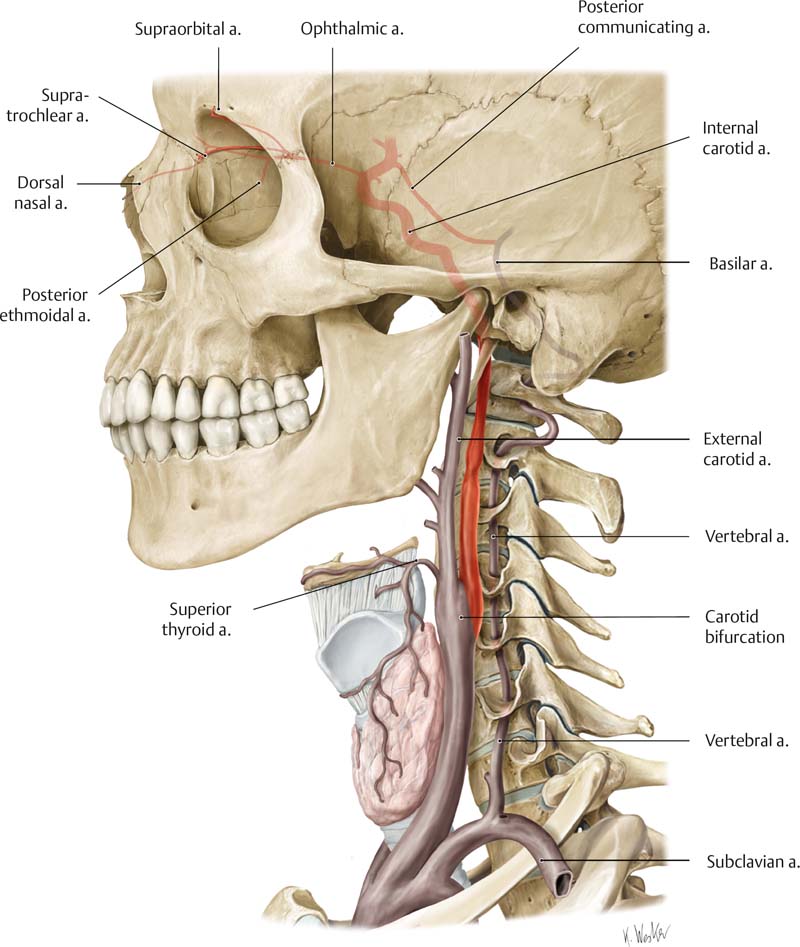
From Atlas of Anatomy, © Thieme 2008; illustration by Karl Wesker.
Normal Imaging
 Video 13.2). In color Doppler mode the transverse view with an angulated transducer demonstrates the different flow characteristics of the internal and external carotid arteries (Fig. 13.8;
  Video 13.3). The flow characteristics of the ICA are typically a constant flow forward during the systolic and diastolic cycles (Figs. 13.9, 13.10;
  Video 13.4). The ECA is more pulsatile as a result of a higher peripheral resistance (Figs. 13.11, 13.12, 13.13;
  Video 13.5). The CCA signal is a “mixture” of both the ECA and the ICA spectra (Figs. 13.14, 13.15, 13.16, 13.17;
  Videos 13.6, 13.7, 13.8). The anatomical position of the ECA cannot be used to discriminate between the ICA and ECA. There might be misinterpretation of the broad diastolic flow of the ECA in cases of stenosis and occlusion of the ICA that will form a large collateral flow via the ECA. In case of doubt, a rhythmic tapping of the superficial temporal artery in front of the tragus will give typical alterations in the waveform that can easily be demonstrated in the Doppler spectrum. The carotid bulb shows a typical reverse flow, indicated by a changeover of color from red to blue (Fig. 13.18). In color mode a reversed coloration will be seen in some zones of the carotid bulb opposite the ECA.
Intima–Media Thickness
Atherosclerotic Disease
Plaque imaging
Related posts:
Stay updated, free articles. Join our Telegram channel

Full access? Get Clinical Tree


