Hand and Wrist
Thomas H. Berquist
Protocols
Routine radiographs
Hand: posteroanterior (PA), lateral, oblique views
Wrist: PA, lateral, scaphoid views
Wrist motion (instability) series: PA views with radial deviation, ulnar deviation, and clenched fist; lateral views with dorsal and palmar flexion
Computed tomography (CT)
Two- to 3-mm axial and direct coronal or sagittal images for conventional studies. Axial images at 1- and 0.5-mm intervals for coronal and sagittal reformatting or three-dimensional reconstruction.
Magnetic resonance imaging (MRI)
Field of view: 8 to 12 cm
Coil: wrist coil or flat 5-inch coil (motion studies)
Patient position: arm at side when possible; otherwise, arm above head (Table 9-1)
TABLE 9-1 MAGNETIC RESONANCE IMAGING PARAMETERS | ||||||||||||||||||||||||||||||||||||||||||||||||||||||||||||||||||||||||||||||||||||||||||||||||||||||||||||
|---|---|---|---|---|---|---|---|---|---|---|---|---|---|---|---|---|---|---|---|---|---|---|---|---|---|---|---|---|---|---|---|---|---|---|---|---|---|---|---|---|---|---|---|---|---|---|---|---|---|---|---|---|---|---|---|---|---|---|---|---|---|---|---|---|---|---|---|---|---|---|---|---|---|---|---|---|---|---|---|---|---|---|---|---|---|---|---|---|---|---|---|---|---|---|---|---|---|---|---|---|---|---|---|---|---|---|---|---|
| ||||||||||||||||||||||||||||||||||||||||||||||||||||||||||||||||||||||||||||||||||||||||||||||||||||||||||||
Suggested Reading
Berquist TH. MRI of the musculoskeletal system. Philadelphia: Lippincott Williams & Wilkins; 2006:719–801.
Schweitzer ME, Natale P, Winalski CS, et al. Indirect wrist MR arthrography: The effects of passive motion versus active exercise. Skel Radiol 2000;29:10–14.
Truong NP, Mann FP, Gilula LA, et al. Wrist instability series: Increased yield with clinical-radiological screening criteria. Radiology 1994;192:481–484.
Fractures/Dislocations: Distal Radius/Ulnar Fractures—Colles Fracture
Key Facts
Fractures of the distal radius are common. In elderly patients, osteopenia results in fracture from minor trauma. In children, incomplete or physeal fractures are common. Fractures of the ulna or ulnar styloid commonly occur with distal radial fractures.
Distal radial fractures have multiple eponyms such as Colles, Smith, Barton, and Chauffeur’s fractures. Today most are categorized by the extent of articular involvement. Type A fractures are extra-articular, Type B fractures are partial articular, and Type C fractures involve both the radiocarpal joints and distal radioulnar joint (DRUJ).
Colles fracture is a term applied to fractures to distal radial, with or without articular involvement, and dorsal displacement of the distal fragment.
Mechanism of injury: fall on the outstretched hand.
Anteroposterior (AP) and lateral radiographs are diagnostic. However, CT is often performed to completely evaluate articular involvement.
Treatment: traction to reduce and reachieve radial length and palmar tilt. Closed reduction usually is successful.
Complications: occur in up to 33% of patients and include
Compressive neuropathy
Arthrosis
Malunion
Tendon rupture
Ligament injuries
Ischemic contractures
 FIGURE 9-1 Lateral radiograph of the wrist demonstrating incomplete fractures of the ulna (arrowhead) and a torus (buckle) fracture of the radius (curved arrow). |
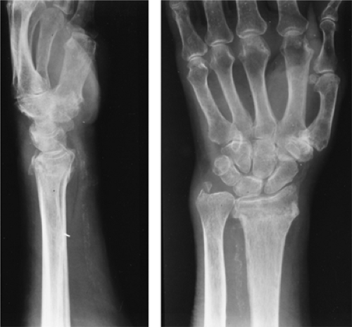 FIGURE 9-2 Lateral and PA radiographs of the wrist showing a typical Colles fracture with dorsal impaction of the radius and an ulnar styloid fracture. The fracture extends into the DRUJ (Type B). |
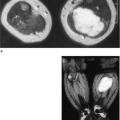
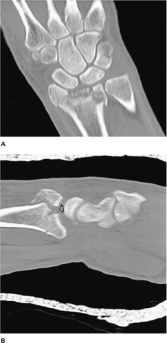 FIGURE 9-3 Coronal (A) and sagittal (B) CT images clearly demonstrate the fracture fragments and the extent of articular separation (open arrow in B). |
 FIGURE 9-4 PA radiograph of an old Colles fracture with shortening of the radius and decreased radial inclination (lines). There is degenerative arthritis and an associated fifth metacarpal fracture (arrow). |
Suggested Reading
Cooney WP, Dobyns JH, Linscheid RL. Complications of Colles’ fractures. J Bone Joint Surg 1980;62A:613–619.
Orthopedic Trauma Association Committee for Coding and Classification. Fracture and dislocation compendium. J Orthop Trauma 1996;10:26–30.
Fractures/Dislocations: Distal Radius/Ulnar Fractures—Smith Fracture
Key Facts
Smith fracture is a “reverse Colles fracture” with palmar displacement of the distal radial fragment.
Mechanism of injury: fall on a palmar flexed wrist.
Treatment: closed reduction; restore radial length. Internal fixation may be required with significant displacement or articular involvement.
Complications: identical to Colles fracture complications.
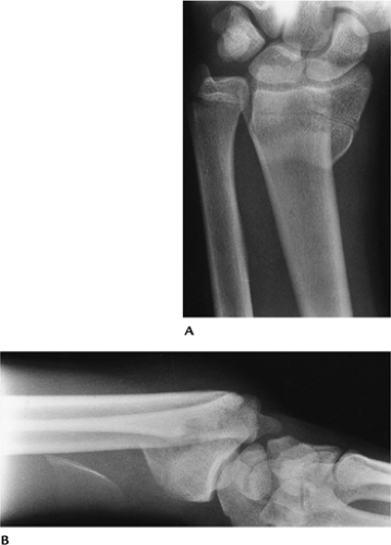 FIGURE 9-5 AP (A) and lateral (B) radiographs of a Smith fracture with palmar displacement of the distal radius. |
Suggested Reading
Thomas FB. Reduction of Smith’s fracture. J Bone Joint Surg 1957;37B:463–470.
Fractures/Dislocations: Distal Radius/Ulnar Fractures—Barton Fracture
Key Facts
A Barton fracture is an intra-articular fracture of the radius involving the dorsal or volar lip of the radial styloid.
Radial styloid fractures are divided into three zones. Zone I fractures may be stable without associated ligament injuries. Zone II fractures commonly have associated ligament injury. Zone III fractures are likely to have ligament injury and joint incongruency (Fig. 9-6).
Mechanism of injury: Palmar fractures occur similar to Smith fractures. Dorsal fractures result from a fall on the outstretched hand with the forearm pronated.
Treatment: closed reduction unless the articular surface cannot be restored. In the latter setting, internal fixation may be required.
Complications: similar to Colles fracture, except subluxation and arthrosis are more common.
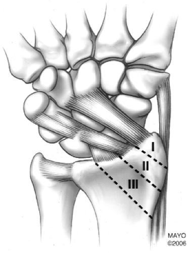 FIGURE 9-6 Zones of radial styloid (Barton fracture). Zone I: styloid tip, may be stable with no ligament injury. Zone II: possible ligament injury, may have articular deformity. Zone III: likely to have ligament injury and joint deformity. |
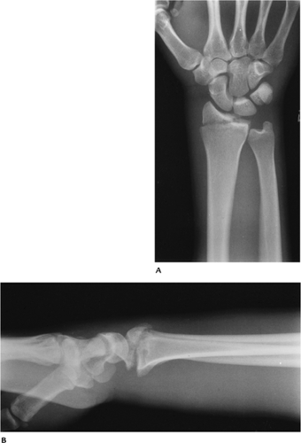 FIGURE 9-7 Dorsal Barton fracture. AP (A) and lateral (B) radiographs of an intra-articular fracture of the lateral aspect of the radius. |
Suggested Reading
DeOliveira JC. Barton’s fracture. J Bone Joint Surg 1973;55A:586–594.
Putnam MD. Radial styloid fractures. In: Blair WF, ed. Techniques in hand surgery. Baltimore: Williams and Wilkins; 1996:322–329.
Fractures/Dislocations: Distal Radius/Ulnar Fractures—Chauffeur’s Fracture
Key Facts
A Chauffeur’s fracture is an intra-articular fracture of the distal radius that predominately involves the radial styloid.
The fracture line typically enters the joint at the junction of the scaphoid and lunate fossae.
Mechanism of injury: axial compression transmitted through the scaphoid. Decades ago, the injury was associated with backfires resulting in the automobile starting crank striking the wrist.
AP and lateral radiographs are adequate for diagnosis.
Treatment: cast immobilization if minimally displaced. Percutaneous K-wires may be required to maintain reduction.
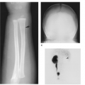
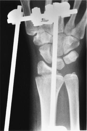 FIGURE 9-8 PA radiograph of a Chauffeur’s fracture during reduction with an external fixation. |
Suggested Reading
Wood MB, Berquist TH. The hand and wrist. In: Berquist TH, ed. Imaging of orthopedic trauma, 2nd ed. New York: Raven Press; 1992:749–870.
Fractures/Dislocations: Galeazzi Fractures
Key Facts
The Galeazzi fracture is a fracture of the distal radius, usually diaphysis, with associated subluxation or dislocation of the DRUJ.
Mechanism of injury: fall on the outstretched hand with hyperpronation of the forearm.
Treatment: reduction and internal fixation.
Routine radiographs are diagnostic.
Complications: malunion of the fracture and residual subluxation of the DRUJ.
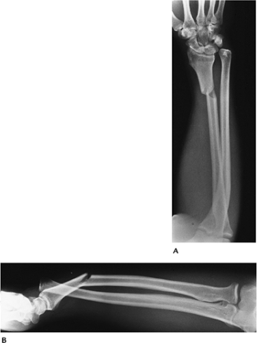 FIGURE 9-9 PA (A) and lateral (B) radiographs showing a distal radial fracture with dislocation of the DRUJ. |
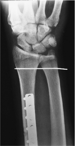 FIGURE 9-10 PA radiograph after plate and screw fixation of the radial fracture and K-wire fixation of the joint. |
Suggested Reading
Wood MB, Berquist TH. The hand and wrist. In: Berquist TH, ed. Imaging of orthopedic trauma, 2nd ed. New York: Raven Press; 1992:749–870.
Fractures/Dislocations: Distal Radioulnar Joint Subluxation/Dislocations
Key Facts
Subluxation or dislocation of the DRUJ may be dorsal (most common) or volar.
Mechanism of injury:
Dorsal—hyperpronation injury
Volar—hypersupination injury to the forearm
Routine radiographic findings may be subtle. Axial CT or MRI with the wrist in pronation, neutral, and supinated positions is most useful to confirm the diagnosis.
Treatment: Closed reduction and cast immobilization may be successful. Open repair may be best for long-term results and optimal stability.
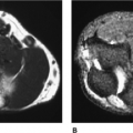
 FIGURE 9-11 Axial fat-suppressed T2-weighted magnetic resonance (MR) image showing dorsal subluxation of the ulna (arrow) and absence of the extensor carpi ulnaris tendon (open arrow) as the result of a complete tear. |
Suggested Reading
Hamlin C. Traumatic disruption of the distal radioulnar joint. Am J Sports Med 1977;5:93–96.
Nakamura R, Horie E, Imaeda T, et al. Criteria for diagnosing distal radioulnar joint subluxation by computed tomography. Skel Radiol 1996;25:649–653.
Fractures/Dislocations: Scaphoid Fractures
Key Facts
The scaphoid is the most commonly fractured carpal bone in adults, accounting for 70% of all carpal injuries. Scaphoid fractures in children account for only 2.9% of hand and wrist fractures.
Mechanism of injury: fall on the outstretched hand.
Scaphoid fractures may be difficult to detect and treat. Nonunion and avascular necrosis (AVN) are common complications.
Scaphoid fractures are classified by fracture location and orientation of the fracture line. Fractures may involve the (1) tubercle, (2) distal articular surface, (3) fracture of the distal third, (4) waist fracture, or (5) proximal pole fracture (Fig. 9-12).
Imaging of scaphoid fractures requires AP, lateral, and scaphoid views. Displacement or obliteration of the navicular fat stripe is a useful sign for subtle fractures. Radionuclide scans, MRI, or CT may be useful for detecting subtle fractures and evaluating complications.
Treatment: cast immobilization for undisplaced fractures. Displaced fractures (>1 mm step-off or angulation) are treated with internal fixation.
Complications: delayed union (failure to unite in 3 months), nonunion, malunion, AVN (most common with proximal pole fractures), radioscaphoid impingement, and arthrosis.
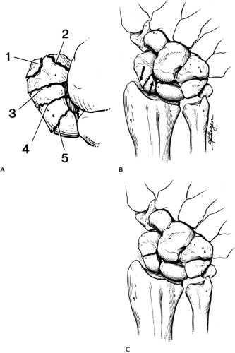 FIGURE 9-12 (A) Locations of scaphoid fractures: 1, tubercle; 2, distal articular surface; 3, distal third; 4, waist; 5, proximal pole. (B) Oblique fracture. Shearing forces (arrows) lead to instability and displacement. (C) Transverse waist fracture is more stable. |
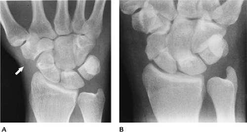 FIGURE 9-13 (A) Subtle scaphoid fracture with absent navicular fat stripe (arrow). (B) Displaced scaphoid waist fracture. |
 FIGURE 9-14 Humpback deformity. (A) Sagittal proton density-weighted MR image demonstrates fluid (open arrow) in the fracture line and deformity (white lines) caused by dorsal separation of the fracture’s fragments. (B) Sagittal reformatted CT image demonstrates a similar humpback deformity (lines) with sclerosis of the proximal fragment caused by AVN. |
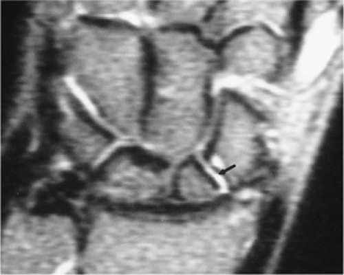 FIGURE 9-15 Coronal T2-weighted MR image showing fluid (arrow) between the fragments caused by nonunion. |
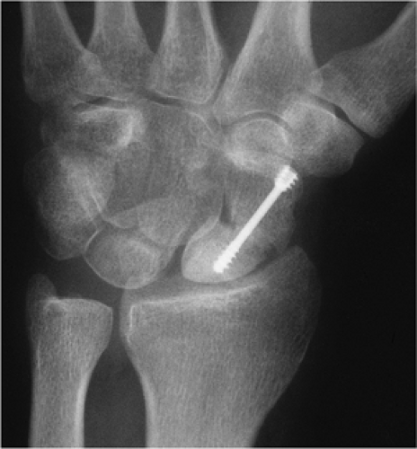 FIGURE 9-16 PA view of a displaced scaphoid fracture with Herbert screw fixation. The proximal pole is sclerotic because of AVN.
Related posts:Stay updated, free articles. Join our Telegram channel
Full access? Get Clinical Tree
 Get Clinical Tree app for offline access

|