Orthopedic Appliances and Prostheses
Thomas H. Berquist
Internal Fixation Systems
Key Facts
There are numerous internal fixation devices, most with a specific indication or anatomic design.
Selection of the appropriate system depends on the indication (e.g., fracture, neoplasms), patient’s clinical status, and surgical preference.
Common devices and indications are summarized as follows:
Device
Indication/Application
Cortical screws
Threaded entire length. Should penetrate opposite cortex by 1 to 2 mm. Often used with plates.
Cancellous screws
Wider threads, may be partially threaded. Most commonly used in cancellous bone or metaphysis.
Interference screws
Fully threaded with no heads. Used to fix bone plugs or tendon grafts.
Soft tissue anchors
Used for soft tissue attachment to bone.
Dynamic compression screws
Allow bones to impact. Usually used with a side plate.
Plates
Common in variable lengths and configurations. Straight—diaphyseal fixation. Special—metaphyseal and epiphyseal fixation.
Intramedullary fixation
Stabilize fracture without exposing fracture site. Most commonly used in humerus, tibia, and femur. Static configuration—screws in both ends of device. Dynamic configuration—screws in one end only.
Complications of internal fixation:
Loosening and screw pullout
Soft tissue irritation from protruding screws
Stress risers from screw holes
Instrument failure
Infection
Loss of reduction
Delayed union, malunion, or nonunion
Imaging of fixation devices can be easily accomplished using serial radiographs. Thin-section computed tomography (CT) with reformatting in the coronal and sagittal planes is useful for evaluating healing and delayed or nonunion. Detection of infection may require radionuclide scans or magnetic resonance imaging (MRI).
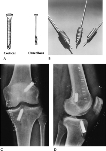 FIGURE 16-1 Screws. (A) Fully threaded cortical and partially threaded cancellous screws (courtesy of Zimmer, Warsaw, IN). (B) Interference screws. Anteroposterior (AP) (C) and lateral (D) radiographs of the knee after anterior cruciate ligament repair. The interference screws secure the bone plugs at the ends of the tendon graft. |
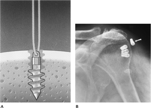 FIGURE 16-2 Soft tissue anchors. (A) Revo cancellous screw and suture for anchoring soft tissues (courtesy of Linvatec, Largo, FL). (B) Shoulder radiograph after rotator cuff repair using soft tissue anchors. One of the anchors (arrow) has pulled out. |
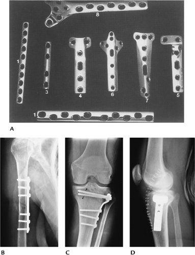 FIGURE 16-3 Plate and screw fixation. (A) Straight dynamic compression plates (1), one-third tubular plate (3), T-buttress (4), and L-buttress plates (5), cloverleaf plate (olecranon fixation) (6), spoon plate (7), and condylar buttress plate (distal femur) (8). (B) Midhumeral fracture internally fixed with a dynamic compression plate and cortical screws. (C,D) Tibial plateau fracture reduced using a T-buttress plate, and proximal cancellous (arrowheads) and distal cortical screws. |
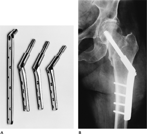 FIGURE 16-4 Dynamic compression screw. (A) Dynamic compression screws with side plates of different lengths and femoral neck angles. (B) Intertrochanteric fracture reduced using a dynamic hip screw and four-hole side plate with cortical screws. |
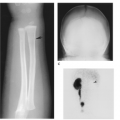
 FIGURE 16-5 Intramedullary nails. Solid (A) and hollow (B) intramedullary nails with proximal and distal holes for screws. AP (B) and lateral (C) radiographs of a midtibial fracture with static (screws at both ends) intramedullary nail fixation. The fracture margins are sclerotic (arrow) because of delayed union. |
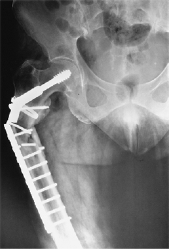 FIGURE 16-6 Implant failure. AP radiograph of the right femur with fracture of the side plate and several screws. |
Suggested Reading
Behrens F. A primer of fixation devices and configurations. Clin Orthop 1989;24:5–14.
Berquist TH, Broderson MP. General orthopedic fixation devices. In: Berquist TH, ed. Imaging atlas of orthopedic appliances and prostheses. New York: Raven Press; 1995:45–108.
External Fixation Systems
Key Facts
External fixation systems, common in numerous configurations, can be designed for specific anatomic regions and may be designed to allow joint motion.
External fixation systems may be unilateral, ring configuration, rectangular, or partially circumferential.
There are three major goals for external fixation systems:
Allow access to the injured area
Avoid injury to vital structures
Meet the mechanical demands of the injury
Advantages of external fixation include
Limited soft tissue injury with insertion
Pins can be used as handles to reduce fractures
Improved wound access
Early motion of involved joints
Complications of external fixation systems include
Pin tract infection
Loss of reduction
Soft tissue or neural injury
Imaging of fixation pins may require fluoroscopically positioned spot views. Serial radiographs are useful for monitoring fracture position.
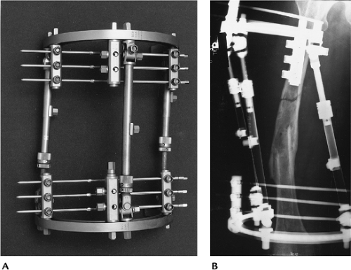 FIGURE 16-7 Fisher external fixation. (A) Fisher fixation system. (B) Radiograph of a refractured femur reduced using Fisher external fixation. |
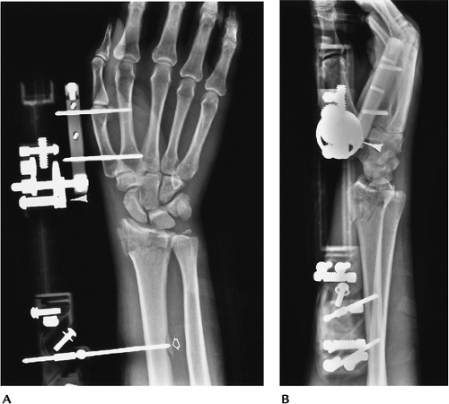 FIGURE 16-8 Colles fracture with external fixation. The system (arrowhead) allows wrist motion. Posteroanterior PA (A) and lateral (B) radiographs showing external fixation of a Colles fracture. Note the proximal pin (open arrow) has fractured the distal cortex. |
Suggested Reading
Behrens F. General theory and principles of external fixation. Clin Orthop 1989;241:15–23.
Berquist TH, Broderson MP. General orthopedic fixation devices. In: Berquist TH, ed. Imaging atlas of orthopedic appliances and prostheses. New York: Raven Press; 1995:45–108.
Traction
Key Facts
Traction can be used for brief periods to assist with fracture reduction or for longer periods to improve fragment position before more definitive therapy.
Traction devices use smooth or threaded pins.
Traction is most commonly used for distal femoral fractures. Certain other extremity fractures, such as the humerus, also may be treated with traction.
Traction pins for lower extremity injuries can be placed in the distal femur, proximal tibia, or calcaneus. Calcaneal traction carries a higher incidence of infection.
Imaging of injuries treated in traction requires serial studies to monitor position of fragments (ensures proper weight on traction device). Two views at 90 degrees taken at the bedside usually are sufficient.
Complications include
Pin tract infection
Pin loosening
Shortening or rotation (too little weight)
Soft tissue interposition when fragments are too distracted (too much weight)
 FIGURE 16-9 Traction. (A) Thomas splint for lower extremity traction (courtesy of Zimmer, Warsaw, IN). AP (B) and lateral (C) radiographs of a supracondylar femur fracture treated in traction. There are two threaded traction pins in the upper tibia. |
Suggested Reading
Berquist TH, Brodersen MP. General orthopedic fixation devices. In: Berquist TH, ed. Imaging atlas of orthopedic appliances and prostheses. New York: Raven Press; 1995:45–108.
Spinal Instrumentation: Long Segment Instrumentation
Key Facts
The most common indication for long segment spinal instrumentation is scoliosis.
Preoperative imaging, measurement techniques, and cause were discussed in Chapter 3.
Both anterior and posterior instrumentations have been used. The latter is more common.
Anterior instrumentation (shorter segments):
Dwyer system: titanium cable, staples, and cancellous screws
Advantages
Excellent primary curve correction
Disadvantages
Secondary curve response uncertain; cable fracture; kyphotic effect
Zielke system: modified Dwyer; cable replaced with steel rod placed through slotted cancellous screws
Texas Scottish Rite Hospital system: similar to Zielke
Posterior instrumentation systems use rods (compression and/or distraction), hooks, cross links (improve rotational stability), and sublaminar wires.
Complications of scoliosis instrumentation include
Loss of correction
Rod fracture
Hook displacement
Screw pullout
Pseudarthrosis
Infection
Neurologic injury
Imaging of complications
Most instrument failure complications can be detected on serial radiographs.
Diagnosis of infection may require radionuclide scans and fluoroscopically guided aspirations for culture.
Pseudarthrosis may be difficult to identify unless motion radiographs show obvious changes.
Radionuclide scans (>9 months after surgery), CT, or MRI may be required to detect pseudarthrosis.
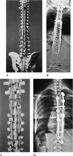 FIGURE 16-10 Posterior long segment instrumentation. (A,B) Luque instrumentation. (A) Smooth Luque rods, sublaminar wires, and proximal and distal “H” bars (arrowheads). (B) PA radiograph with multiple Luque rods, sublaminar wires, and proximal and distal cross links (arrowheads). (C,D) Cotrel-Dubousset instrumentation. (C) Diamond-point surface rods with hooks and cross links. (D) PA radiograph after Cotrel-Dubousset instrumentation. |
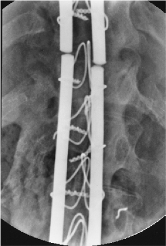 FIGURE 16-11 Rod fracture. AP radiograph of fracture of Luque rods caused by pseudarthrosis. |
Suggested Reading
Dawson EG, Clader TJ, Bassett LW. A comparison of different methods used to diagnose pseudarthrosis. J Bone Joint Surg 1985;67A:1153–1159.
Ohashi K, Bennet DL, Restrepo JM, et al. Orthopedic hardware complications diagnosed with multidetector row CT. Radiology 2005;237:570–577.
Spinal Instrumentation: Short Segment Instrumentation
Key Facts
Short segment instrumentation is commonly used for trauma, degenerative disease, spondylolisthesis, and neoplasms.
Surgical approaches may be anterior, posterior, or combined.
Common instrumentation includes interbody cages, disc replacement, plates, rods, rectangles, pedicle screws, vertebral body screws, and bone grafting.
Preoperative imaging varies with the indication:
Indication
Imaging Technique
Degenerative disease/spondylolisthesis
Routine radiographs
Flexion-extension views (measure subluxation, stability)
CT—pedicle screw size
Discogram—confirm source of pain
Trauma
Routine radiographs
CT—fragment position, pedicle screw size
MRI—neural injury
Vertebral replacement
Routine radiographs
CT—bone loss
MRI—soft tissue, neural involvement
Complications of short segment instrumentation:
Instrument failure
Pedicle screw malposition
Displaced interbody devices
Pseudarthrosis
Neural injury
Adjacent disc or facet disease
Postoperative imaging varies with the suspected complication. Most complications can be detected on serial radiographs. Imaging of other complications can be approached similar to long segment instrumentation complications.
 FIGURE 16-12 Trauma: fracture/dislocation at T12. AP (A) and lateral (B) radiographs showing reduction using Isola rods, with pedicle screws at L1 and L2 and hooks proximally. Generally, fixation should include two to three vertebrae above and below the injury. |
 FIGURE 16-13 Vertebral body replacement. AP (A) and lateral (B) radiographs showing a titanium interbody cage and anterior vertebral body screws and rods (Kenada device) for fixation. |
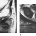
 FIGURE 16-14 Pedicle screw complications. Axial CT image (A) demonstrating good positioning of pedicle screws in the pedicle and body (thick arrows) of L5. AP radiograph after myelography (B) demonstrates rod and pedicle screw instrumentation from L3 to the sacrum. Coronal CT image (C) shows the lower right pedicle screw extending into the foramen (arrow). |
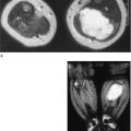
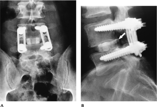 FIGURE 16-15 AP (A) and lateral (B) radiographs with plate and pedicle screw instrumentation posteriorly and a bone graft in the L4–5 disc. The graft has displaced posteriorly (arrow) into the spinal canal resulting in neurologic deficit. |
Suggested Reading
Togawa D, Bauer TW, Lieberman IH, et al. Lumbar intervertebral body fusion cages: Histologic evaluation of clinically failed cages retrieved from humans. J Bone Joint Surg 2004;86A:70–79.
Tropiano P, Huang RC, Girardi FP, et al. Lumbar total disc replacement. J Bone Joint Surg 2006;88A:50–64.
West JL, Ogilvie JW, Bradford DS. Complications of the variable plate pedicle screw fixation. Spine 1991;16:576–579.
Shoulder Arthroplasty
Key Facts
Glenohumeral joint replacement is the technique of choice for patients with painful articular disorders (Table 16-1) who do not respond to conservative therapy.
Prognosis and selection of technique (total joint replacement vs. hemiarthroplasty) varies with the extent of bone, joint, and soft tissue involvement. New reverse shoulder components are now used for patients with severe rotator cuff deficiency.
Preoperative evaluation includes clinical scoring for pain, function, and range of motion plus imaging of the involved shoulder.
Radiographs: AP, Neer view, axillary
CT: Bone stock, especially glenoid
MRI: Soft tissue involvement
Component and procedure selection:
Constrained system: rotator cuff mechanism loss and inadequate soft tissue support; high incidence of loosening; not commonly used today
Nonconstrained system: adequate soft tissue support
Hemiarthroplasty (humeral component only): avascular necrosis of the humeral head; normal glenoid
Postoperative imaging/complications:
Complications of shoulder arthroplasty are summarized in Table 16-2. Imaging varies with suspected complication.
TABLE 16-1 SHOULDER ARTHROPLASTY INDICATIONS | |
|---|---|
|
TABLE 16-2 SHOULDER ARTHROPLASTY COMPLICATIONS | ||||||||||||||||||||
|---|---|---|---|---|---|---|---|---|---|---|---|---|---|---|---|---|---|---|---|---|
|
| Complication | Imaging Technique |
|---|---|
| Glenoid loosening | Serial fluoroscopically positioned spot views |
| Humeral component loosening (>2-mm lucent lines) | Serial radiographs |
| Humeral component subsidence | Serial radiographs |
| Subluxation/dislocation | Serial radiographs |
| Neural injury | MRI |
| Infection | Radionuclide scans or MRI |
| Humeral fracture | Serial radiographs |
Related posts:

Stay updated, free articles. Join our Telegram channel

Full access? Get Clinical Tree


