Head and Neck Cancers
Ping Xia
Quynh-Thu Le
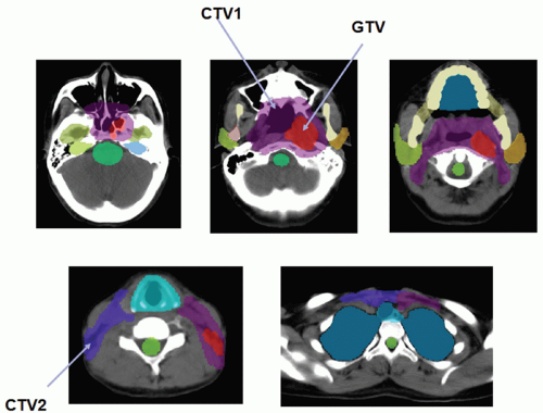
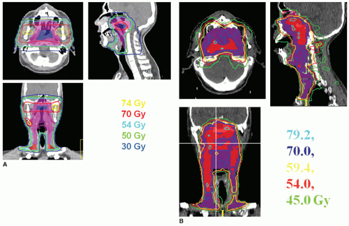
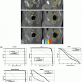
Radiotherapy, either alone or delivered concurrently with chemotherapy, is a definitive treatment modality for head and neck squamous cell carcinomas. As shown in Figure 10.1, the volumes that need to be irradiated in head and neck cancers (HNCs) are complex, making it challenging to adequately irradiate the entire targeted volumes while still safely protecting adjacent normal tissues. Many critical structures such as the brainstem, the optic apparatus, and the parotid glands are often located within a few millimeters from the treatment volumes; yet the differences in tumoricidal doses and tolerance doses of the normal structures are often large, demanding a concave dose distribution and steep dose gradients at the tumor boundaries. Conventional two-dimensional (2D) radiotherapy and, quite often, three-dimensional (3D) conformal radiotherapy (CRT) cannot meet these stringent requirements due to their inability to produce sophisticated dose distributions, resulting in reluctant compromise between adequate tumor coverage and protection of sensitive structures. Advancement of computer optimization and intensity-modulated radiation therapy (IMRT) significantly improved the conformity of the dose distributions as well as the gradient of dose fall-off. Figure 10.2 shows the superior dose distribution of an IMRT plan when compared to a conventional plan.
Although early clinical results1, 2, 3, 4, 5, 6, 7, 8, 9, 10, 11, 12, 13, 14 of 3D-CRT and IMRT for patients with HNCs are promising, uncertainties in the radiation delivery of these sophisticated plans become a great concern.15, 16, 17, 18, 19, 20, 21, 22 In particular, the question of whether these highly conformal dose distributions can be precisely delivered to the patients over a protracted course of 6 to 7 weeks of treatment becomes paramount. Specifically, can we safely reduce the planning margins while patient positioning uncertainties persist? Can these problems be solved with implementation of image guidance? What kind of image guidance is optimal in these patients? In this chapter, we will try to address these questions and review practical strategies of applying imaging guidance in radiation management of HNC patients.
PATIENT POSITIONING ERRORS, PLANNING MARGINS, AND IMAGE GUIDANCE
Although some forms of immobilization devices are often used for HNC, inter- and intratreatment uncertainties are unavoidable. Hurkmans et al.21 performed a comprehensive review of setup variability in portal imaging studies from several institutions for the various body sites, including head and neck regions. They found that the interfraction uncertainties ranged from 1.7 to 4.6 mm for each major axis and 1.1 to 2.5 mm in systematic and random variations in HNC patients. The systematic error is defined as the standard deviation of the mean variation for each patient, averaged over the entire patient population, whereas the random error is defined as the standard deviation of each measured variation over the entire patient population. By introducing a customized neck support and an electronic portal imaging device (EPID)-based 3D offline correction protocol, van Lin et al.23 reported an improvement in the overall patient setup, with systematic errors of 0.8 to 1.1 mm and random errors of 1.1 to 1.7 mm in each translational axis, resulting in a reduction of the planning margins from 5 to 10 mm to 3 to 4 mm. Interestingly, using an optically guided patient localization system that is capable of accounting for all six degrees of freedom, Hong et al.20 reported a composite vector offset of 6.97 mm, which is significantly greater than the value of 3.33 mm noted for 2D portal imaging. Conversely, Wu et al.24 recently reported only a 1- to 2-mm difference in each translational axis between 2D and 3D imaging methods. These data indicate large disparities in accuracy of patient positioning among different patient populations and different patient setup protocols, requiring more detailed investigations.
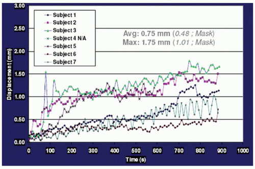
Data concerning intrafraction movement for HNC patients are scarce. Using a commercial stereotactic infrared (IR) camera (ExacTrac; BrainLAB, Heimstetten, Germany) to monitor intrafraction motion during treatment, Kim et al.15,25 reported that the vector displacement was <1.5 mm for 95% of treatment time, with a maximum displacement of 2.0 mm. Interestingly, using six nonpatient volunteers, they found that overall displacement escalates as the treatment duration increases, as shown in Figure 10.3, indicating that treatment duration is another factor to consider. We have performed a systematic study in which 28 HNC patients who planned to undergo head and neck radiotherapy were evaluated. All of the patients were immobilized using a customized Accuform head holder, a thermoplastic mask extending from the cranium to below the mandible, and a customized “peg board” to reproduce the shoulder position. Patients then underwent a positron emission tomography (PET) scan with a computed tomography (CT) scan for attenuation correction, as well as a treatment planning contrast-enhanced CT scan, both performed in the same setting without moving
the patient. The two CT scans were coregistered in the head and upper neck region and registered separately in the shoulders using our institutional computer software. Both translational and rotational motions were assessed in six dimensions. The motion observed between the two CT scans, which were obtained approximately 20 minutes apart while the patient remained immobilized, serves as a surrogate for intrafraction motion during radiotherapy under the ideal condition. We found that the average absolute intrafraction motions in the head and upper neck were all <1 mm. However, more motion was noted in the shoulder, where the absolute translational motion was >5 mm in nine patients (31%) in the lateral, anterior-posterior, and superior-inferior directions.26
the patient. The two CT scans were coregistered in the head and upper neck region and registered separately in the shoulders using our institutional computer software. Both translational and rotational motions were assessed in six dimensions. The motion observed between the two CT scans, which were obtained approximately 20 minutes apart while the patient remained immobilized, serves as a surrogate for intrafraction motion during radiotherapy under the ideal condition. We found that the average absolute intrafraction motions in the head and upper neck were all <1 mm. However, more motion was noted in the shoulder, where the absolute translational motion was >5 mm in nine patients (31%) in the lateral, anterior-posterior, and superior-inferior directions.26
Knowing unavoidable patient positioning uncertainties and adding a proper planning margin to the clinical target volumes (planning target volume [PTV]) and sensitive structures (planning target at risk volume [PRV]) is a practical way to assure adequate dose coverage to the tumor volume and protection to the sensitive structures. However, the PTV and PRV often overlap one another, resulting in conflicting treatment planning goals and requiring an optimal planning margin. Based on analysis of 3D-CRT treatments, van Herk et al.27,28 proposed a margin receipt formula of 2.5Σ + 0.7α − 3 mm, where Σ and α are systematic errors and random errors, respectively. This receipt is estimated with 1% tumor control probability (TCPpop) loss for prostate plans with clinically reasonable values of Σ and α. Whether this margin receipt can be applied to HNC patients is unclear. Using the assumption of Σ = α = 3 mm, Siebers et al.29 simulated the dosimetric effects of systematic and random errors for head and neck IMRT plans and concluded that only 5.4% of IMRT plans exceeded a dose deviation >5% if a 3-mm planning margin is applied, which is much smaller than the calculated margins of 6.6 mm if the margin formula is used with Σ = α = 3 mm. Furthermore, Siebers et al.29 stated that random patient setup errors up to 5 mm minimally impacted the target and critical structure dose coverage, whereas 3-mm systematic errors negatively affected the dose distribution. At both the University of California, San Francisco (UCSF) and Stanford University, we use nonuniform planning margins, and the size of the margins depends on the anatomic relationship between the tumor and its surrounding critical structures. In general, we use a smaller PTV margin (1 to 3 mm) for tumors located adjacent to the brainstem or optic apparatus and a relatively large PRV margin (2 to 3 mm) for these critical structures. In these cases, we permit the planning priority to protect the brainstem and the optic apparatus, whereas for tumor located adjacent to less critical structures such as the parotid glands, we permit the planning priority to cover the tumor volume.
STRATEGIES OF ADAPTIVE RADIOTHERAPY
Stay updated, free articles. Join our Telegram channel

Full access? Get Clinical Tree


