Fig. 54.1
Visualizing both RF-ablation (red arrows) and cryoablation (freezing) lesions (yellow arrows) placed in a swine heart using the LGE pulse sequence. Note the different appearance of cryo lesions (completely bright) versus RF lesions (white rim with dark interior), which is due to excessive ablation, causing charring, in the RF case. To reduce excessive ablation, irrigated catheters are now used
In addition, MRI can potentially be used to triage patients both before and after the EP procedure. Before the procedure, imaging can be used to weigh-in the effectiveness of various treatment options [64], while after the procedure, it may detect the potential for complications [65] or the possibility of conduction recurrence prior to the advent of symptoms.
While MRI has many proven and potential advantages, it is also an uncommon and somewhat unfriendly modality in the EP lab. The dimensions of MRI magnets are larger than most equipment present in the EP lab, which creates space issues and complicates patient monitoring while they are inside the bore. In addition, the magnetic field of the MRI extends beyond its physical dimensions, which creates a restricted zone in which only MRI-safe tools are allowed. Many of the devices found in a typical EP tool set are not MRI safe (i.e., they can potentially move in a strong magnetic field), and only a small fraction of the tools are MRI compatible (i.e., create minimal artifacts and also do not increase in temperature above 2 °C, as a result of absorption of energy at the MRI’s Larmor (rf) frequency, when used during imaging inside the MRI bore). Currently, most MRI imaging is diagnostic in nature, so that it may require long acquisition times and disrupt the EP workflow. In addition, cardiac-MRI techniques were, until quite recently, not robust for imaging smaller and rapidly moving anatomy, such as the left atrial wall. Finally, high-resolution MRI imaging requires repeatedly cyclical cardiac events, so it is ill suited for imaging patients with arrhythmia at the time of imaging and requires that patients be in sinus rhythm, mostly using premedication, during imaging.
What an Integrated MRI-Guided EP System Should Include
MRI-guided EP systems are still in the prototype stage and will surely evolve as the field advances. Today, due to the lack of devices and of temporally effective processes for performing all of the procedure within the MRI, most of the systems utilize MRI only in selected portions of the procedure, while X-ray and ULS imaging are used in the rest.
Electrophysiology (X)-MR-Guided Interventional Suites
In the current state of the art, EP scanning and interventional suites are connected by a transport table that shuttles the patient between the MRI scanner and the interventional suite, where the interventional table and the X-ray system are found. Such systems are offered by all the MRI scanner manufacturers (GE, Philips, Siemens), as well as by Brainlab [66]. A major limitation of such a system is the need to move the patient between the interventional suite and the imaging modality. During an EP procedure, a patient is connected to a variety of life support, anesthesia, patient monitoring, and drug-administration lines, all of which need to move with the patient. Such motion therefore requires a large staff and a considerable amount of time. A variant on the classic X-MR suite is the IMRIS [67] cardiovascular suite, in which the X-ray and the MRI are suspended from the ceiling and brought over the interventional table, without moving the patient. Limitations of the IMRIS system include its complexity, large suite footprint, and high cost.
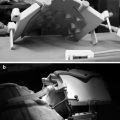
The Stanford University (Norbert Pelc and Rebecca Fahrig) developed the first clinical MRI-compatible X-ray system [68], which was used for combined X-ray and MRI-guided vascular intervention in the liver. The Sunnybrook (Graham Wright and Robert Normand) group has substantially advanced this concept, by building a cone-beam X-ray system that can be placed in the front of the MRI gantry (Robert Normand, Sunnybrook Health Sciences, Toronto, ON, private communication 2012) (Fig. 54.2). This may prove to be a cost-effective solution for EP and other vascular catheter-based procedures, requiring minor patient motion (~1 m), which is efficiently enabled by a floating interventional table, reducing the requirement for multiple rooms and expensive magnets and patient transport.
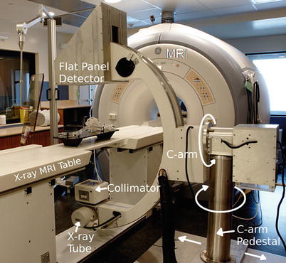
Fig. 54.2
Prototype MRI-compatible X-ray system developed by the Sunnybrook group, which allows for performance of X-ray 1 m in front of the MRI gantry. This system has a rotating anode X-ray source and a flat panel detector that are not sensitive to the MRI’s magnetic field. In the future, such a design may be optimal for those who wish to perform vascular intervention without moving the patient over large distances and who do not want to invest in the large suites required for current X-MRI systems (Courtesy Normand Robert, Sunnybrook Health Sciences Institute, Toronto, ON, Canada)
Navigation and Guidance
Navigation and guidance, in the EP atrial- or ventricular-ablation context, commonly require navigation from the femoral or vertebral veins to the right side (right atrium) of the heart, a transseptal puncture between the cardiac atria, followed by navigation in the left side (left atrium or left ventricle) of the heart. Alternative navigation strategies use arterial access, so navigation is performed from the femoral artery to the aorta and then through the cardiac valves into the heart. Arterial access is less common, since it is more difficult to perform.
The navigational stage of the EP procedure can be performed under X-ray/EAM, ICE, or under MRI guidance. A current X-ray advantage is the maneuverability and visibility of the metal guidewire, which allows the transseptal puncture site to be rapidly found. X-ray procedures, however, require contrast injections which can be contraindicated for renal-compromised patients. ICE overcomes the limitations of X-ray guidance and is now used frequently to determine the exact position of intra-atrial septum perforation.
Under MRI, the procedure commonly requires acquisition of a contrast-enhanced 3D MR angiography (MRA) scan, which is then used as a roadmap for navigation. Additional MRI scans can also be used for navigation, such as wall-motion (cine) scans and T2-weighted scans. MRI-guided navigation can be performed using either passive or active tracking.
With passive tracking, conventional high-speed MRI imaging is performed and the device is detected based on its magnetic-susceptibility artifacts (metallic devices), its lack of signal (nonmetallic devices), or its use of locally enhanced MRI signal (Gd-DTPA-filled tubes or resonant-rf devices). Passive tracking normally allows for 1–3 frames per second (fps) and requires a great deal of operator interaction. The procedure generates considerable acoustic noise and hearing protection for the patient and medical staff is required. Passive tracking is also limited to tracking a single device, whereas EP interventions typically require simultaneous tracking of multiple devices.
Active tracking of devices requires special catheters that incorporate micro-coils for the detection of tracking signals. Two approaches are currently in use. In the first approach, the micro-coils detect MR signals generated by a special MR-tracking [69] pulse sequence (e.g., at the Larmor frequency), which is the most prevalently used technique. In the second approach, electrical fields induced in the micro-coils, in the KHz range, by the MR system’s gradient subsystem during ramps and falls are detected and used to compute coil position (Robin Medical [70]), which demands use of high-slew-rate MRI sequences. Active tracking is far more temporally efficient and spatially accurate than passive tracking, allowing for a spatial resolution of ~1 mm3 at a rate of 20 fps. Furthermore, these tracking specifications can be maintained simultaneously for multiple coils incorporated into multiple devices, so that multiple devices can be tracked, which is a necessity in electrophysiology. The complicating factor in active tracking is the need for use of specialized devices and the need to modify MRI pulses sequences in order to use the devices. Happily, there are several manufacturers who are making preclinical EP devices with tracking micro-coils on board, including St. Jude Medical [28], Imricor [71], and MRI Interventions [72], with some of these companies planning FDA submission in the near future. In addition, all the major MRI manufacturers now provide some version of the required (MR tracking) pulse sequences.
Whichever tracking technique (passive or active) is used, MR-guided navigation typically uses pre-acquired MR image data as a roadmap and then superimposes the position of the device on the MR image display. With such a display, the electrophysiologist can navigate devices without additional imaging, unless gross patient motion occurs.
If needed, real-time (4–5 fps) MRI imaging and device tracking can be used together. In this mode, the location of the catheter tip is continuously determined and then used to define the location of subsequent MR images. The position of the imaging slice can be determined by passive tracking or alternatively by interleaving active tracking and imaging [73]. The disadvantage of real-time imaging is that sub-second MRI images are typically low in spatial resolution and poor in CNR. This mode of imaging is advantageous when changes in anatomy/physiology occur, since these changes cannot be seen when navigation is based on roadmaps. Consequently, combined tracking and imaging is frequently used during transseptal puncture and during therapy delivery. Another use of real-time imaging is to re-register the pre-acquired roadmaps after patient motion. This can be done by comparing the real-time image with a pre-acquired image data set obtained in approximately the same place/orientation to find the pre-acquired image which has the highest correlation with the current image.
Requisite Interventional Devices (Catheters, Sheaths, Guidewires, Needles)
A typical EP procedure requires multiple surgical and interventional devices. Many of the standard surgical devices (for the vascular cutdown, for suturing, etc.) have MRI-compatible analogs, primarily as a result of a long history of MRI-guided procedures in other body regions, including the brain or the abdomen.
There are fewer EP-specific MRI-compatible devices available today, and the number of FDA-regulatory cleared devices is very small.
The most difficult devices to make MRI compatible are EP devices that have stringent mechanical requirements, such as guidewires and deflectable EP ablation catheters incorporating metallic pull wires and braided shafts. Construction difficulty increases as the devices become smaller and if active tracking of the device is required.
Electrophysiology use typically requires 32–38 × 10−3 in. guidewires. The Terumo Glidewire [74] guidewire, which is regulatory cleared (although not specifically for MRI use), is made of nitinol and has been used for coronary MRI-guided procedures without any complications reported. There are also two European companies (BIOTRONIK [75] and Fraunhofer IPT [76]) currently working on plastic guidewires with nitinol tips (passively visualized), which are MRI compatible. One of them has received regulatory clearance in Europe and has been recently used for MRI-guided human procedures. In the past, SurgiVision, Inc. (now MRI Interventions [72]) produced an active FDA-cleared 14 × 10−3 in. imaging guidewire for coronary use, which was based on their loopless antenna rf-coil concept. This guidewire was used in multiple animal and human experiments without any reported adverse effects, and it could be used for passive tracking, since it appears hyper-intense inside an MRI.
EP mapping and radio-frequency ablation require deflectable catheters, typically 7–9 French in diameter. The most common of these catheters are used for linear mapping/ablation and have 2–8 metallic electrodes on their shaft for intracardiac-ECG measurement or for delivering RF-ablation energy. They possess multiple positional sensors for localization and usually an integrated temperature probe (using thermocouple or fiber-optical principles). For electrical connectivity of all these sensors, a catheter may thus have 6–12 cables running along its shaft. The tip electrode is 4–8 mm in length and contains a substantial amount of metal, whereas most of the other electrodes are thin 2–4 mm long rings. The catheters are typically braided over a significant length of their shaft to maintain mechanical rigidity, and they employ 1–2 pull wires to allow remote deflection of the tip. Non-MRI-compatible EP catheters typically contain ferromagnetic materials and are not useful inside the MR imaging system. Several MRI-compatible catheters have been developed for preclinical work, and a few are being advanced and tested for future human use. Most of these have replaced the ECG electrodes with nonferrous (paramagnetic) materials, such as gold or platinum, with some employing material combinations of diamagnetic and paramagnetic substances that result in low-paramagnetism mixtures, which do not create large susceptibility artifacts inside the MRI. With regard to the catheter braiding, MRI compatibility may require replacing the braid material with a nonferrous metal or alloy or with a polymer, while the pull wire may undergo a similar change. Some, or all, of the electrical cables may need to be replaced, if they generate noise at the MR scanner’s Larmor frequency or can heat up, due to cable resonances (standing waves) which are efficiently coupled to within the MRI bore.
In addition, the EP community is moving in the last few years to increased use of irrigated EP ablation catheters, which employ a steady infusion of saline to prevent the tip from heating above 50 °C during current delivery, thereby improving the ability to produce larger volume ablation lesions with less collateral tissue damage. In addition, this type of catheter is less prone to develop thrombus and clot at the tip of the catheter during heating, while the ablation lesion is created, thus reducing the likelihood of systemic embolization and stroke. Constructing irrigated MRI-compatible EP catheters is an even more difficult engineering task, since the catheter now requires an additional water lumen. Furthermore, tip irrigation does address, in part, the fear of rf-pulse-induced catheter heating in the MRI, since it has been shown [77] that it is possible to reduce heating inside the MRI by using continuous irrigation, and indeed, the new Imricor, St. Jude Medical, and MRI Interventions catheters are all irrigated.
The two most widely EAM techniques used today, the Biosense Webster Carto and the St. Jude Medical NavX, do not function inside the MRI in their standard configuration, so modifications or a replacement of the tracking technique may be required. The BWH/Cincinnati Children’s group is actively working with SJM on making the NavX system MRI compatible and has already conducted animal interventional experiments with such a system [78].
This discussion will not cover more complex mapping catheters, such as lasso catheters, which are being increasingly used to improve the EP workflow, but the challenges in making them MRI compatible are similar to those described above. An additional type of catheter needed for some EP procedures is the stimulation/pacing catheter. These are generally somewhat smaller (6–7 French) than ablation catheters, are not deflectable, and usually have 4–6 ECG/positional electrodes on their shaft. Stimulation/pacing catheters are usually placed in the coronary sinus and are used to provide near-heart pacing, as well as to provide a reference to compensate for respiratory-induced motion, since they allow the EAM map to move dynamically as the patient breaths. Making MRI-compatible pacing/stimulation catheters is generally easier than making deflectable EP catheters.
Sheathes are another critical device in an EP procedure. The majority of sheaths used in EP are open plastic tubes with a variety of tip curvatures. Many sheaths can be made MRI compatible without much effort by simply cutting off the tip X-ray visible ring found on many of them. There are a variety of deflectable sheathes gaining prominence in the EP community, and making them MRI compatible is a more complex task, but of a similar nature, to that discussed above for the mapping and ablation catheters. In addition, MRI-visible positional sensors may need to be placed on these sheathes, to have them appear visible inside the MRI.
A third instrument that is usually important for EP is the needle kit. These kits are required to perforate the atrial wall (transseptal puncture) or for injection of various substances into the ventricular wall, such as contrast or stem cells. The needle kit is usually composed of three devices: an introducer, which is outside the needle; a metallic needle guide; and the (thinner) needle. The introducer is usually nonmetallic and MRI compatible, while the needle and needle guide are made of strong, and usually ferrous, steel. Active MRI-compatible needles were previously manufactured by Boston Scientific [79] and used extensively at the NIH [80] and at John Hopkins to perform preclinical studies of MRI-guided treatment of infarcted myocardium using targeted stem-cell injections to the boundaries of the injured tissue.
Clinical MRI-Compatible ECG Systems for Electrophysiology Use
High-fidelity ECG measurements in electrophysiology are of supreme importance. In a conventional EP procedure, 5–12 surface ECG electrodes are attached to the patient’s chest, and an additional 10–64 electrodes may be simultaneously sampled for intracardiac voltages. ECG electrodes can also be used for delivery and detection of current (<1 W, <200 Hz), for stimulating or pacing tissue.
ECGs fulfill three purposes in an EP intervention: (1) Surface ECGs are used for patient monitoring (as in any other intervention), (2) Surface ECGs provide timing references for the intracardiac electrograms, and (3) intracardiac ECGs are used to measure voltages on the walls of the cardiac chambers to establish the conduction paths in the heart. In terms of fidelity, ECG traces used in EP should contain 0.5–300 Hz spectral content and support 0.05–20 mV amplitude with a noise level held at <0.02 mV, so that even weak intra-infarct ECGs can be detected.
Acquisition of high-quality ECGs inside an MRI is complicated by several effects. For example, during MR image acquisition, magnetic field gradient pulses are employed. During the rise or fall of these magnetic field gradient pulses, voltages are induced in the patient, which are detected by the ECG electrodes. These overlaid voltages are frequently much stronger than the physiological ECG, and corrupt ECG fidelity.
For a patient lying inside an MR magnet, the magnetohydrodynamic (MHD) effect of conductive blood moving within the body creates voltages which are superimposed on top of the physiologic ECG trace. MHD voltages are strongest from blood flow in the aortic arch, which has peak velocities at the end-systolic phase of the cardiac cycle. The MHD voltage increases with magnetic field strength, and its intensity changes with patient heart rate and blood pressure [81, 82] (i.e., the mechanical function of the heart). The most problematic aspect of the MHD effect (Fig. 54.3) is that it occurs at the same time as the S-T segment of the cardiac cycle. During EP procedures, this segment is continuously monitored to capture changes in the ECG due to acute ischemic events. The MHD issue is especially troublesome in the electrophysiology context, since all VT patients have ischemic histories and many AF patients have associated functional cardiac disease.
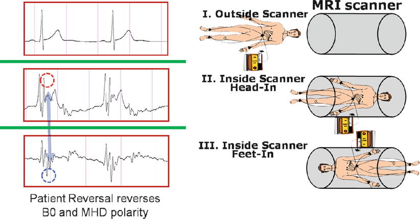
Fig. 54.3
ECG acquired outside (I) and both head (II) and feet (III) inside an MRI scanner. Note the magnetohydrodynamic artifacts inside the MRI (red and blue dotted circles), which reverse as the patient orientation is inverted
Finally, the intracardiac-ECG cabling used in EP is not just used to receive ECG signals emanating from the heart but also to conduct RF-ablation signals (500 KHz, 10–30 W) from an RF generator to the EP ablation catheter.
As a result of the challenges described above, ECG systems for MRI-compatible EP may be quite complex. Conventional MRI-compatible ECG triggering systems, built by the four MRI scanner vendors and also by Medrad and Invivo, commonly utilize 4–6 surface electrodes which are placed in close proximity to one another, high electrical-impedance transmission lines (>50 kohm, usually made of carbon fiber), and low-pass (<50 Hz) filters to reduce gradient noise and reduce the risk of rf heating. In addition, many of these have recently changed to short leads followed by wireless ECG transmission. Such systems, while safe for use in the MRI environment, are optimized for the detection of the R wave and are used primarily for triggering data acquisition of the MR system. Unfortunately, they (1) provide low-fidelity ECG signals, (2) have difficult in sensing whether a lead is not well connected, and (3) cannot be used to conduct the 500 KHz RFA current to the catheter.
Vector cardiograms (VCGs) have been used to reduce ECG distortions caused by the MHD effect [83], but due to the close proximity of electrode placement (<10 cm overall distance) in the MRI-compatible 4-lead ECGs, the VCG utility does not function well enough to accurately display the true S-T segment signal while the patient is in the magnet, and it may even fail to show the QRS complex when a high-field MRI (3 T) is used or when high-slew-rate cardiac-MRI sequences, such as steady-state free precession (SSFP), are used.
There have recently been developments in this field. Scientists at MRI Interventions, Imricor, Philips, and GE have developed MRI-compatible ECG recording systems and demonstrated high-fidelity intracardiac-ECG recordings inside the MRI. For improved surface ECG fidelity, the BWH/Cincinnati Children’s group has been developing an MRI-compatible 12-lead ECG system, which uses software processing to remove MHD artifacts present when measuring ECGs inside the magnet bore and also uses specific hardware to remove the gradient noise produced when the MRI is pulsing [84], while other groups have developed software gradient noise reduction methods [85].
Safety (Pacemakers, Implantable Cardiac Defibrillators, External Defibrillators)
Many cardiac patients have implanted electronic devices such as pacemakers and implantable cardiac defibrillators (ICDs). These devices are rf-shielded boxes containing a battery and electronics, which are placed in pockets under the skin. Electrical wires exit the boxes and go to specific regions in the heart, where they sense physiologic voltages and deliver electrical currents as required to offset pathological conditions. Many implanted devices require replacement of components every few years, and in some patients, remnants of older devices (e.g., old pacemaker leads) are left inside the heart.
Imaging patients with implanted devices rarely results in damage to the device itself, although there have been reports of devices requiring reprogramming after MRI imaging. The largest source of concern is that the wire leads may act as antennas in the MRI’s radio-frequency field and induce unsafe heating of tissue, leading to burns and/or blood coagulation. A few studies of patients with implanted devices have been conducted at 1.5 T [86], and some hospitals, such as John Hopkins and Oklahoma Heart, actively image patients with implanted devices under IRB approval.
Recently, Medtronics [87] has been granted regulatory clearance for an MRI-compatible pacemaker (Ensura MRI SureScan) and leads (586 CapSureFix MRI SureScan lead), and there are expectations of other vendors following suit, so the problem of unsafe pacemakers, which currently leads to an exclusion of a large number of patients from MRI-guided EP interventions, such as VT procedures, may gradually disappear.
Heating of EP devices in the MR environment is a worry. A long conductor inside the MRI’s radio-frequency excitation coil has the potential to couple with the electric field and support an electrical standing wave along its length. This standing wave can create strong electric fields around the device that interact with tissue and cause local heating. Since the electric field created by the body coil in an MR scanner is zero along the central axis of symmetry (i.e., the Z axis of the magnet) and increases with the radial distance from this axis, the potential for heating increases as one moves the conducting structure further towards the interior wall of the magnet. Despite this fear, there have been very few reported cases of internal heating in the animal EP studies performed to date. The main reason for the lack of heating is the fact that EP devices are commonly navigated inside blood vessels, where there is rapid transport of heat away from the device due to the flowing blood. Nevertheless, FDA regulations require that body heating should not exceed 2 °C, and several of the vendors preparing human-grade devices for regulatory clearance are working to reduce the risk of heating using a variety of passive and active electronic methods [88, 89].
An additional potential source of heating is the ECG electrodes (patches) placed on the patient’s skin. There have been reports of burns due to these electrodes, which have resulted in vendor requirements that the contact area between electrodes and the skin be sufficiently large and that the electrical leads running from the patches to the ECG recording devices (typically, distances of several meters) include measures to reduce the rf current flowing in them.
Placement of defibrillator pads on a patient is a requirement for conduction of EP ablation, since shocking (cardioverting) the patient, in situations where intra-MRI VT or VF occurs, must be performed using an in-room external defibrillator (usually found on the “crash cart” in the interventional suite) with the minimal delay possible. As is the case with ECG pads, defibrillator pads and leads that are placed on the patient may heat, so specially modified defibrillator pads and leads must be constructed. A prototype an MRI-compatible portable defibrillator was recently built by MRI Interventions [72] for the University of Utah (Dr. Marouche) group.
Present and Emerging MRI Pulse Sequences for EP
A variety of MRI pulse sequences are used in MRI-guided EP, and the list of these will expand over time. At present, all diagnostic cardiac-MRI sequences are candidates for use in a cardiac EP study. As a rule of thumb, the more severe demands of interventional procedures require that only robust sequences be used, since repeating a failed scan extends the procedure time. In addition, interventional imaging commonly requires higher spatial resolution than diagnostic imaging, primarily during the treatment-monitoring phase, so high robustness is required.
Since EP patients have irregular cardiac rhythms, robustness to changing heart rate and occasional arrhythmia events, such as premature ventricular contractions (PVCs), are an important factor. For most cardiac MR imaging, sinus rhythm during data acquisition is needed, and antiarrhythmic drugs or cardioversion may be required prior to the procedure. The use of antiarrhythmic drugs, however, is often frowned upon, as it may suppress the arrhythmia that itself must be induced and mapped. Since respiratory motion is a challenge in MR, imaging sequences should be equipped for two modes of operation: low-resolution or limited-coverage imaging that can be completed in less than a breath hold, as well as longer-duration high-resolution imaging with respiratory motion synchronization (e.g., utilizing respiratory gating or a respiratory navigator echo).
Anatomic sequences are acquired primarily in the pre-interventional stage of the procedure. Mapping the lumen of the cardiac chambers at high spatial resolution, for use as navigational roadmaps, is mostly performed today with ECG-triggered contrast-enhanced 3D MR. At some sites, luminal imaging is performed with un-gated rapid multi-temporal-phase non-gated 3D MRA (TRICKS, TWIST, etc.), which can be performed faster, but frequently result in blurred lower-resolution images. There is also a growing use of non-contrast-enhanced MRA, using T2-weighted or arterial spin-labeling preparation pulses with SSFP or gradient-echo (GRE) readouts. Non-contrast MRAs [90] have the advantage of allowing for selective vessel imaging, such as seeing only veins or arteries, and can be performed numerous times during the procedure.
High-resolution anatomic imaging of the vessel walls is mostly performed with variants of “black-blood” ECG-gated 2D or 3D fast (or turbo) spin echo. With these methods, imaging of finer anatomy, such as atrial-wall imaging, can require long scan times. T1- or T2-weighted imaging can be performed, frequently used together with spectral fat suppression in regions of high-fat content, such as the atrial wall. Anatomic wall imaging may become increasingly useful in the future as an alternate to the detection of ablation targets with conventional EP electrical methods. For example, it has been shown that autonomic nerve ganglia that surround the atria, which play a role in stimulating AF, can be detected with fat-suppressed T1-weighted GRE or SSFP imaging [91]. Anatomic imaging is also useful for setting up a baseline for comparison with intra-procedural or post-procedural imaging, thereby enhancing the detection of areas affected by ablation or by other processes performed during the procedure, such as inadvertent puncture of a wall or esophageal heating.
Multiple cardiac-phase wall-motion (“cine”) imaging is frequently performed, using either SSFP or GRE pulse sequences. Cine imaging can be used for determining potential ablation targets, especially for ventricular EP interventions, where a dysfunctional wall can indicate infarction. 3D Cine protocols can be used for creation of 4D (multiple cardiac-phase 3D) roadmaps for navigation, which may allow for more accurate navigation.
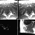
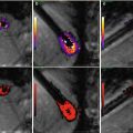
3D late gadolinium enhancement (LGE), which is also termed myocardial delayed enhancement in the MRI physics literature, is currently the standard for detection of necrotic wall regions. As such, it plays a key role in determination of target areas for ablation in MRI-guided VT procedures (Fig. 54.4), since it can identify both necrotic zones and the surrounding “stunned” regions. It also plays a role in the assessment of ablation lesions, both in the left ventricle and the left atrium (Fig. 54.5), especially since it has now been demonstrated in several studies [92, 93] that it accurately detects gaps in ablation lesions in the chronic post-procedural setting (>2 days post-procedure) (Fig. 54.6). There is a current controversy over whether LGE in the acute post-ablation setting accurately predicts the degree of ischemic tissue in the chronic setting, which is important in assessing whether the lesions created are of sufficient depth or inter-connectivity. This topic is the subject of extensive current research.
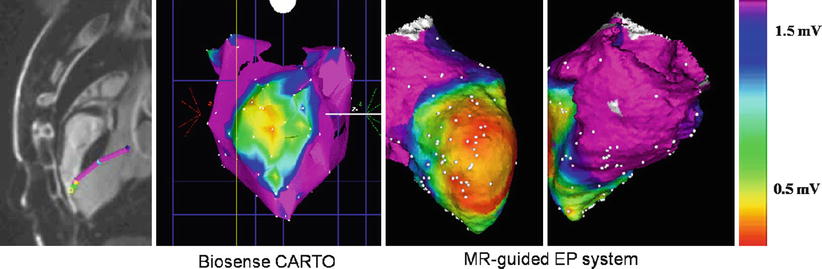
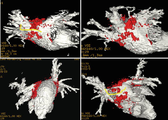
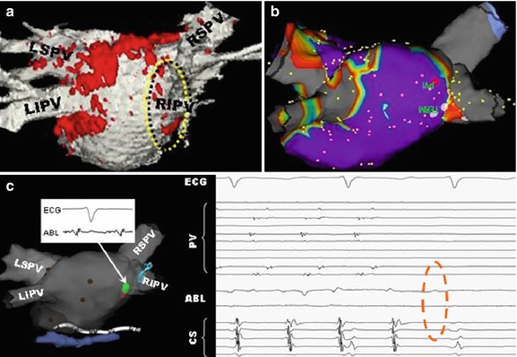
Fig. 54.4
MRI-guided ventricular mapping of infarcts (performed in this case with the GE/Harvard integrated EP system) has major advantages versus conventional EAM mapping, since the mapping is guided by pre-acquired LGE images that tell the electrophysiologist where the infarct is, so the critical area around the infarct is more densely sampled. In cases of diffuse infarcts or infarcts behind areas which are hard to contact, such as the papillary muscle, there may be substantial quality advantages to maps produced with MRI guidance, and in addition, the guidance can save a considerable amount of time
Fig. 54.5
Overlay of LGE (red) lesions over a luminal atrial map (white) in a patient post-ablation shows areas of gaps in RF-ablation lesions (yellow)
Fig. 54.6
Use of LGE intra-procedurally, in a patient that had two prior incomplete RF ablations, in order to find the remaining gaps and close them. (a) Luminal MRA image overlaid with LGE (red) shows one of remaining gaps (yellow circle), which (b) is confirmed using SJM NavX EAM system. During pacing between two catheters, (c) pressure applied to entry circuit terminates fibrillation, which is then (d) permanently terminated by RF ablation (dotted red circle). This patient has been free of AF since this procedure
Strain imaging using myocardial tagging (HARP, DENSE, SENC) is already playing a role in MRI guidance of ICD placement, since it provides quantitative data on dysfunctional regions of the myocardium wall. In the future, it is expected that strain MRI may play a larger role in target tissue definition, and it may provide for non-contrast determination of ablated tissue [94, 95].
MR temperature imaging using the proton resonance frequency shift (PRF) concept may allow, once it is practical, to determine tissue temperature and the cumulative thermal dose delivered during the ablation process. While there has been a recent report of temperature imaging in the heart of a dog model during RF ablation [63] (Fig. 54.7) in which there was little motion, temperature imaging suffers from severe artifacts in moving anatomy and due to lung-heart-interface susceptibility artifacts, which requires continuing research to resolve.
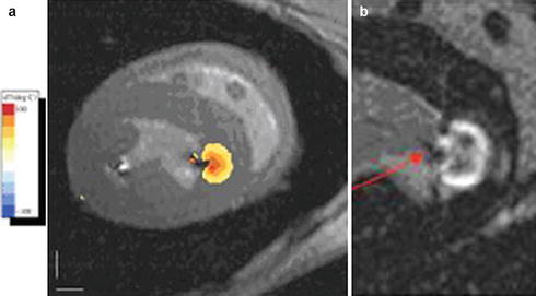
Fig. 54.7
Temperature imaging using the proton resonant frequency shift (PRF) method in a dog model during RF ablation of the left ventricle: (a) Tissue temperature image overlaid on the anatomic image. The orange lesion border indicates 50 °C, chosen to correspond to irreversible tissue damage. (b) Late gadolinium enhancement image of the ablated lesion (arrow), showing the good correspondence with lesion location and depth (Courtesy of Henry Halperin, John Hopkins University)
The “holy grail” of MRI-guided EP is the imaging of current flow patterns in the heart. If this can be realized, it will allow a great deal of the diagnostic phase of the EP procedure to be performed noninvasively. Imaging of current flow using MR is now possible in the brain, using magnetic resonance electrical-impedance tomography (MREIT), due to the small changes in magnetic field (of the order of 10−9 of the static field for milliampere currents) associated with the flow of electrical current [96, 97]. Similar approaches in the heart may be possible, but these will certainly be much more technically challenging and may require some of the technical innovations that will also be needed to make cardiac temperature imaging possible.
Post-processing of MRI Data
The visualization of MRI data by electrophysiologists follows the paradigms found on commercial EAM systems and is mostly composed of 3D surface renderings of anatomy. Most electrophysiologists are not accustomed to viewing MRI slices, although recent products, such as the Biosense Webster CartoSound, now present ULS data as slices.
In present practice, MRI data is sent to the EAM workstation, where it is segmented and then registered to the conventional EAM maps. Both the Carto and NavX systems offer efficient registration packages between MRI and EAM data, usually based on identifying a set of discrete anatomic points in both data sets, as well as for the display of surface rendered MRI data following its segmentation. Multiple contrast MRIs, such as LGE, T2, and MRA, may be segmented jointed, or sequentially, and then fused with the EAM system, which allows visualizing areas of wall scar, as well as wall edema, on a background usually composed of the chamber’s luminal surface.
Patient Physiological Monitoring and Defibrillation
Electrophysiologic procedures targeting ventricular tachycardia are often performed on patients with a history of ischemic heart disease and heart failure, while those for atrial fibrillation are also performed frequently in patients with structural heart disease. In addition, cardiac arrest due to bradyarrhythmias or ventricular tachyarrhythmias is not unusual during EP procedures. As a result, defibrillation close to, or inside, the MRI is an absolute must. While fully MRI-compatible external defibrillators do not exist, use of energized standard defibrillators in close proximity to the MRI is possible. This requires that the EP procedure be performed with the skin pads placed on the patients for the duration of the procedure and that the “crash cart” be kept close by (perhaps even tethered to the wall in the MRI room). It also requires a fast method to pull the patient out of the bore when an event occurs, so that resuscitation can be performed on the MRI table. MRI-compatible defibrillation pads are currently being studied by several groups.
Patient monitoring is very important in EP procedures, primarily if the patients are intubated during the procedure. End-tidal CO2, SPO2, and IVP are all available from vendors of MRI-compatible products. Four-lead ECGs are also available from these vendors, although 12-lead MRI-compatible ECGs are not currently commercially available (see discussion in a previous section).
Intra-procedural MRI Benefits
Most clinical MRI-guided EP systems used today utilize an X-MR suite, in which the MRI role is primarily restricted to pre- or post-procedural imaging, and the main EP mapping and ablation phases are conducted under ULS, X-ray, and EAM guidance.
The advantage of performing the procedure within the MRI is that it potentially allows for improved navigation, mapping, and delivery of therapy, as well as for visualization of anatomic and physiological changes occurring during these stages. Online and interactive visualization, when performed at critical stages of the procedure, has the potential to reduce risks and improve outcomes of EP procedures. Note that these systems are sometimes referred to as “real-time MRI systems,” but we prefer to use the nomenclature “online interactive,” since “real-time,” for many imaging modalities, corresponds to images acquired at the rate of several frames per seconds, which is not appropriate for MRI-guided electrophysiology, and since real-time MRI imaging is low in both resolution and contrast; whereas in interventional EP, at most procedure stages, other than at specific times during navigation, we desire high spatial resolution and high CNR images, images that cannot be acquired in “real time” with MRI.
Interactive online MRI places more requirements on the interventional devices, and it also requires special user interfaces, which are not commercially available on most diagnostic MRI scanners. Interactive real-time MRI human interfaces are available as research offerings from Philips, Siemens, and MRI Interventions (for Siemens scanners), as well as from HeartVista [98] for GE scanners, and possess varying degrees of sophistication. These interfaces, when mature, will become the MRI analogs of the EAM systems used in commercial EP labs. They allow visualization of the position and orientation of multiple catheters during the MRI procedure, relative to cardiac anatomy. The more advanced interfaces are equipped with interactive switching between tasks, so that they can rapidly alternate between tracking a device using active (or passive) markers and imaging. They can also acquire “guided scans” in which images are acquired at the position and orientation of the tracked device, such as at the tip of the EP ablation catheter. Some systems can also update image data using on-demand retrieval of previously acquired diagnostic image roadmaps, without requiring the lengthy prescription and reacquisition of data that diagnostic scanners require. Some interactive interfaces also allow for rapid switching between several MRI pulse sequences, which allows for visualizing the same anatomy with multiple contrasts.
Related posts:

Stay updated, free articles. Join our Telegram channel

Full access? Get Clinical Tree


