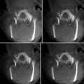
Fig. 49.1
Example of CT-based navigational feedback. This screenshot shows a CT-based navigation during pedicle screw placement (Courtesy of BrainLAB AG, Munich, Germany)
VOs may be acquired at two points in time: either preoperatively or intra-operatively. About two decades ago, first IGOS systems were introduced that were based on preoperatively acquired computed tomography (CT) scans. The advantage of this modality is that it provides excellent bone-soft tissue contrast and is geometrically undistorted. These advantages make CTs superior to magnetic resonance imaging (MRI) as preoperative VOs, although the latter method has clear advantages regarding radiation exposure to the patient. Some efforts have been made to overcome the MRI-related difficulties [6, 7]; however, up to now CT remains the method of choice of preoperative imaging for IGOS applications. Another drawback of preoperative VOs led to the introduction of intra-operative imaging modalities. The bony morphology may have changed between the time of image acquisition and the actual surgical procedure. As a consequence, the VO may not necessarily correspond to the TO any more leading to unpredictable inaccuracies during navigation or robotic procedures. This effect can be particularly adverse for traumatology in the presence of unstable fractures. To overcome this problem in the field of surgical navigation, the use of intra-operative CT scanning has been proposed [8], but the infrastructural changes that are required for the realisation of this approach are tremendous, often requiring considerable reconstruction of a hospital’s facilities. An alternative is the usage of established intra-operative imaging modalities. Several research groups developed navigation systems based on fluoroscopic images [9, 10]. The image intensifier is a well-established device during orthopaedic and trauma procedures and could therefore be integrated into IGOS systems easier than intra-operative CT machines. However, the images generated with a fluoroscope are usually distorted, which is caused by a number of factors. To use these images as VOs therefore requires the calibration of the fluoroscope involving the attachment of marker grids to the image intensifier and the tracking of its position and orientation with the navigator during image acquisition [9, 10]. The resulting real-time visual feedback provided by the navigation system (see Fig. 49.2) is similar to the use of the fluoroscope in constant mode. This technique is therefore also known as “virtual fluoroscopy” [11]. Although only two-dimensional (2-D) projections are available and the images usually lack contrast when compared to CT scans, the advantages of fluoroscopy-based navigation preponderate for a number of clinical applications.
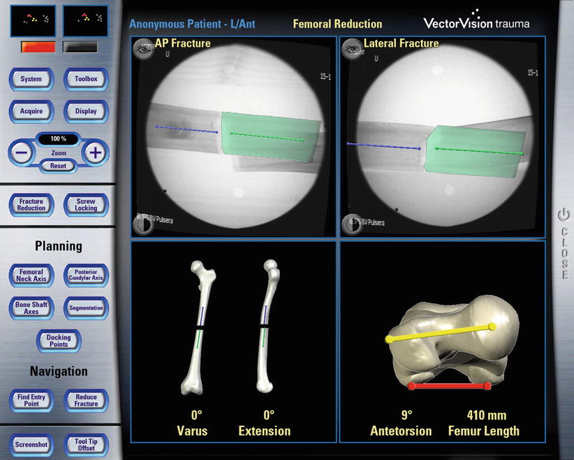
Fig. 49.2
Example of fluoroscopy-based navigation. This screenshot shows the fluoroscopy-based navigation for fracture reduction (Courtesy of BrainLAB AG, Munich, Germany)
In order to address the 2-D projection limitation, a new imaging device was introduced [12] that enables the intra-operative generation of 3-D fluoroscopic image data. It consists of a motorised, iso-centric C-arm that acquires series of 50–100 2-D projections and reconstructs from them 13 × 13 × 13 cm3 volumetric datasets which are comparable to CT scans. Being initially advocated primarily for surgery at the extremities, this “fluoro-CT” has been adopted for usage with a navigation system and has been applied to several anatomical areas already [13–15]. As a major advantage, the device combines the availability of 3-D imaging with the intra-operative data acquisition. “Fluoro-CT” technology is under continuous development involving smaller and noniso-centric C-arms, “closed” C-arm, i.e. O-armTM design [16], faster acquisition speeds, larger field of view, and also flat panel technology.
A last category of navigation systems functions without any radiological images as VOs. Instead, the tracking capabilities of the system are used to acquire a graphical representation of the patient’s anatomy by intra-operative digitisation. Using any tracked instrument, the spatial location of anatomical landmarks can be recorded. Combining the obtained points into lines and surfaces will step-by-step generate an abstract model of the geometry. Because this model is generated by the operator, the procedure is known as “surgeon-defined anatomy” (SDA). The technique is particularly useful when soft tissue structures such as ligaments or cartilage boundaries are to be considered that are difficult to identify on CTs or fluoroscopic images. Moreover, with SDA-based systems, some landmarks can be acquired even without the direct access to the anatomy. For instance, the centre of the femoral head, which is an important landmark during total hip and knee replacement, can be reconstructed from a recorded passive rotation of the leg about the acetabulum. It should be noted that the generated images are often rather abstract and not easy to interpret as exemplified in Fig. 49.3. Sati and co-workers suggested the superposition of a preoperative X-ray to facilitate orientation [17], but the precise matching of the two image spaces turned out to be difficult. An alternative concept is provided by the so-called bone morphing [18, 19]. This technology uses a database of generic 3-D statistical computer models of bones and a set of patient-specific points that are acquired with the SDA technique. Analysing the recorded data lets the system select that bone model from the data pool that best matches the patient’s morphology. A special morphing algorithm would then deform the selected model until it fits the acquired points as good as possible [20]. As the result, a realistic virtual model of the operated structure can be presented and used as a VO without any conventional image acquisition (Fig. 49.4).
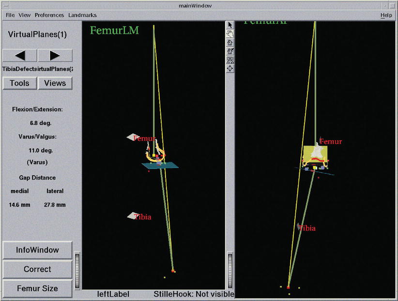
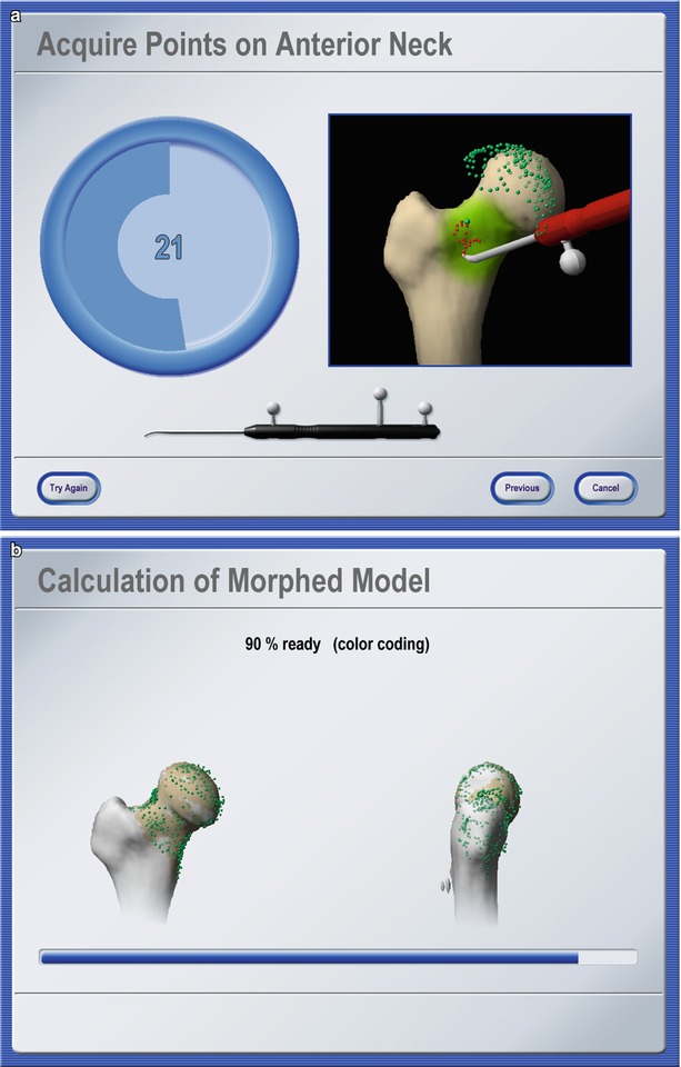
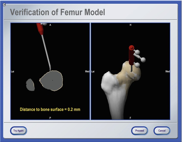
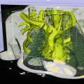
Fig. 49.3
Navigation using surgeon-defined anatomy approach. This virtual model of a patient’s knee is generated intra-operatively by digitising relevant structure. Although a very abstract representation, it provides sufficient information to enable navigated placement of a total knee endoprosthesis
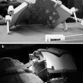
Fig. 49.4
Bone morphing. Screenshots of different stages of an intra-operative bone morphing process. (a) Point acquisition; (b) calculation of morphed model; and (c) verification of final result (Courtesy of BrainLAB AG, Munich, Germany)
Registration
Position data that is used intra-operatively to display the current tool location (navigation system) or to perform automated actions according to a preoperative plan (robot) are expressed in the local coordinate system of the VO. In general, this coordinate system differs from the one in which the navigator operates intra-operatively. In order to bridge this gap, the mathematical relationships between both coordinate spaces needs to be determined. When preoperative images are used as VOs, this step is performed interactively by the surgeon during the registration, also known as matching. A wide variety of different approaches have been developed and realised following numerous methodologies [21].
Early IGOS systems implemented paired-point matching and surface matching [22]. The operational procedure for paired-point matching is simple. Pairs of distinct points are defined preoperatively in the VO and intra-operatively in the TO. The former set of points is usually identified using the computer mouse and marking the desired location within the image data. For the intra-operative acquisition, a probe is used. In the case of a navigation system, it is tracked by the navigator, and for robotic surgery, it is mounted onto the robot’s actuator, which the surgeon then passively guides to the location to be recorded [23]. Once both point sets are available, the transformation that links the underlying coordinate systems can be derived. It is obvious that this procedure is highly interactive during both the preoperative definition of registration points and the intra-operative acquisition of their counterparts. Consequently, this step is error-prone, in particular because a good registration result and thus an accurate performance of the IGOS system strongly depend on the optimised selection of these points and the exact identification of the associated pairs. To improve the accuracy of this step, alternative and complementing techniques have been proposed. Probably most obvious is the implantation of artificial objects to create easily and exactly identifiable spots for paired-points registration [23]. However, the requirement of implanting these objects before the intervention causes extra operation as well as associated discomfort and infection risk for the patient [24]. Consequently, none of these methods have gained wide clinical acceptance. The other alternative that has been widely adopted in early IGOS systems is to complement the paired-point matching with surface matching [25, 26], which does not require implanting any artificial object and only uses the surfaces of the VO as a basis for registration.
Other methods to calculate the registration transformation without the need for extensive preoperative preparation utilise intra-operative imaging. As described above, a calibrated fluoroscope may be utilised to acquire VOs intra-operatively. Since the fluoroscope is tracked by the navigator during image acquisition and if the relation between the fluoroscope’s position in space and the resulting image is known, the 2-D projective representations can be matched with a 3-D CT dataset yielding the registration of the preoperative scan (see Fig. 49.5a, b). From a technical standpoint, such a procedure is non-trivial and is still an active research field. Intensity-based as well as feature-based approaches have been proposed before [21].
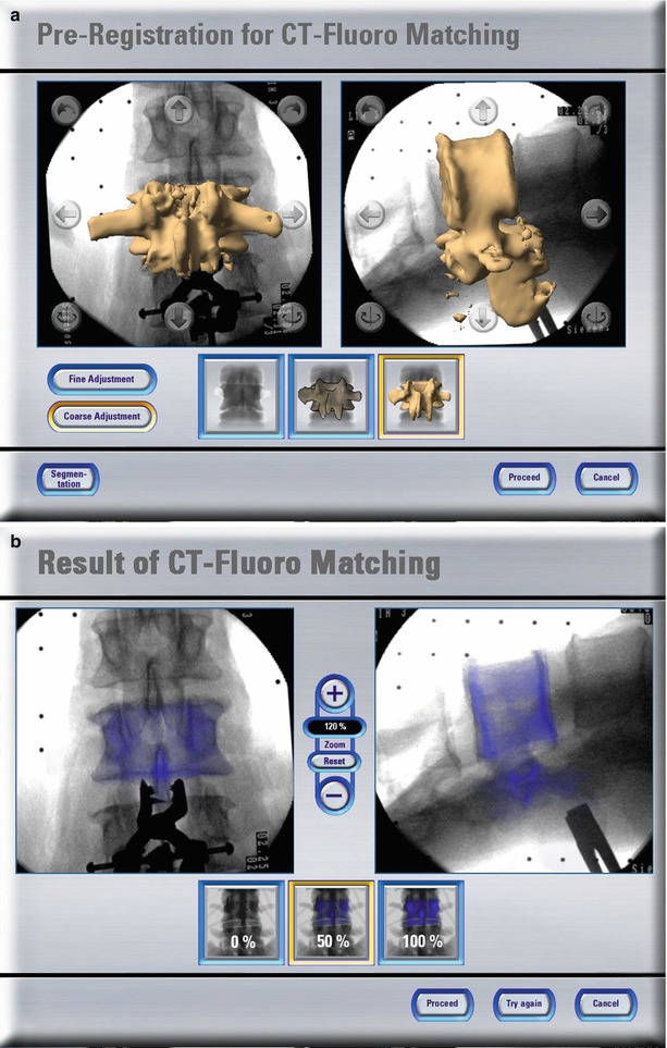
Fig. 49.5
CT-fluoro matching. Screenshots of different stages of a CT-fluoro matching process. (a) Preregistration for CT-fluoro matching; and (b) results of CT-fluoro matching (Courtesy of BrainLAB AG, Munich, Germany)
Another alternative is the employment of intra-operative ultrasonography. If an ultrasound probe is tracked by a navigator and its measurements are calibrated, it may serve as a space digitiser with which position data of the anatomy may be acquired. It thus can replace any other tracked instrument to digitise landmarks for paired-points or surface registration. Two different tracked mode ultrasound probes are available. A (amplitude)-mode ultrasound probes yield the perpendicular depth along the acoustic axis of the device. Placed percutaneously they can measure the distance to tissue borders, and the resulting point coordinates can be processed by any registration algorithm. Although the applicability of this technique has been demonstrated [27, 28], it is not used widely. The nature of A-mode ultrasound requires the probe to be oriented perpendicularly to the bone surfaces that it aims at. Moreover, the velocity of sound varies depending on the properties of the traversed tissues thus leading to unpredictable inaccuracies when used to digitise deeply located structures. As a consequence, the successful application of this technique remains limited to a narrow field of application [29]. In contrast to an A-mode probe, a B (brightness)-mode ultrasound probe scans a fan-shaped area. It is therefore able to detect also surfaces that are examined from an oblique direction (See Fig. 49.6a, b). In order to extract the relevant information for the registration of preoperative CT scans, the resulting, usually noisy images need to be processed either manually [30] or automatically [31]. As for the intra-operative processing of fluoroscopic images, the use of B-mode ultrasound for registration is not reliable in every case and consequently remains subject of IGOS research.
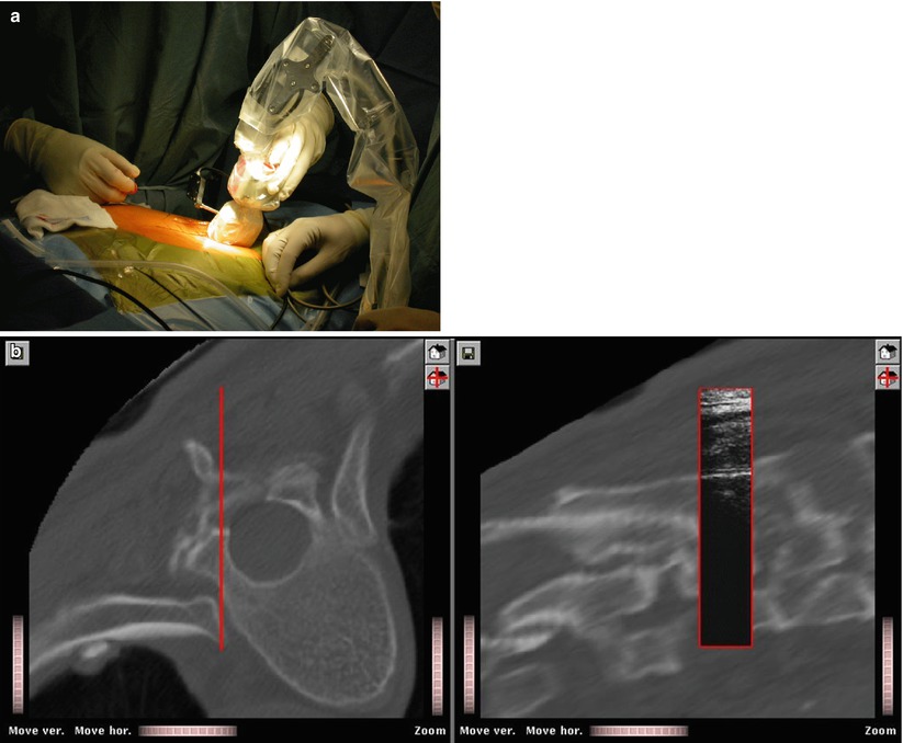
Fig. 49.6
CT-US Matching. An intra-operative setup for B-mode ultrasound-based registration. (a) Intra-operative setup; (b) the final registration results. After registration, ultrasound image information is superimposed onto associated multi-planar reconstructions from the CT data set
If any intra-operative method is used to generate the VO, registration is an inherent process [21]. As stated above, the imaging device is tracked during data acquisition. As a result, the position of the acquired image is known with respect to the TO. This relation corresponds to the interactive registration in the case of preoperative images serving as VOs. Therefore, registration is not an issue when using intra-operative CT, 2-D or 3-D fluoroscopy, or the SDA concept.
Radermacher et al. [32, 33] introduced an alternative way to match preoperative planning with the intra-operative situation using individual templates. The principle of individualised templates is to create customised templates based on patient-specific 3-D bone models that are normally segmented from preoperative 3-D data such as CT or MRI scan. One feature about the individual templates is that small reference areas of the bone structures are integrated into the templates as the contact faces. By this means, the planned position and orientation of the template in spatial relation to the bone are stored in a structural way and can be reproduced intra-operatively by adjusting the contact faces of the templates until an exact fit to the bone was achieved. By integrating holes and/or slots individualised templates function as tool guides, e.g. for the preparation of pedicle screw holes [32, 33] or as cutting jigs used in total knee and hip replacement surgery [34, 35].
Navigator
Registration closes the gap between VO and TO. The navigator enables this connection by providing a global coordinate space. In addition, it links the surgical instruments with which a procedure is carried out, to the TO that they act upon. From a theoretical standpoint, it is the only element in which surgical navigation systems and surgical robotic systems differ.
Robots
For this type of IGOS technology, the robot itself is the navigator. It is registered to the VO, which enables it to realise the plan that was defined by the surgeon in the preoperative image data set. Its actuators carry out specific tasks as part of the therapeutic treatment. Active robots act directly on the patient. They perform a specific task autonomously without additional support by the surgeon. Two robotic systems for total joint replacement have been introduced [4, 5], but their clinical benefit has been strongly questioned [36]. Moreover, they require considerable investments while serving a rather limited portfolio of interventions. As a result, the future of these devices is highly uncertain. For traumatology applications, the use of robots has only been explored in the laboratory setting [37, 38]. This may be a tribute to the nature of fracture treatment which is usually a process that needs to be individualised for each case and does seldom include many standardisable steps that a robot could repetitively carry out.
In contrast to active robotic devices, passive or semi-active robots do not carry out a part of the intervention autonomously but rather guide or assist the surgeon in positioning the surgical tools. At present, there are two representatives of this class that are commercially available, both for bone resection during total knee replacement. The Acrobot system [39] is based on a custom robot. It differs in the purpose that it serves intra-operatively. It holds a high-speed mill that the surgeon is allowed to move freely in order to resect bone as long as this motion stays within a preoperatively defined safety volume. The MAKO system [40] is a passive robotic-arm system with tactile guidance. During the surgical procedure, the system is under the direct surgeon control and gives real-time tactile feedback to the surgeon. Other semi-active robots can be seen as intelligent gauges that place, e.g. cutting jigs or drilling guides automatically [41, 42].
Trackers
The navigator of a surgical navigation system is a position tracking device. It determines remotely the position and orientation of objects and provides these data as 3-D coordinates. From a physical point of view, a number of methods exist to remotely sense the location of objects, and basically, all of them have been implemented in trackers that in turn were used as parts of navigation systems. Most of today’s products rely upon optical tracking of objects using OR compatible infrared light that is either actively emitted from the observed objects or passively reflected by them. In any case, a camera system registers these signals and reconstructs position data. To track surgical instruments with this technology requires the tools to be adapted with probes holding either light-emitting diodes (LED, active) or light-reflecting spheres or plates (passive). Depending on the used tracker model, the active LEDs are powered and controlled either by a cable or remotely, which requires a battery to be housed by the probe as well. Tracking patterns with well-designed geometry by means of video images has been suggested [43, 44] as an inexpensive alternative to an infrared light optical tracker.
Optical tracking of surgical instruments requires a direct line of sight between the tracker and the observed objects. This can be a critical issue in the OR setting. The use of electromagnetic tracking systems has been proposed to overcome this problem. This technology involves a homogeneous magnetic field generated by an emitter coil. Receiver coils are then attached to each of the instruments allowing to measure their position and orientation within the magnetic field. This technique senses positions even if objects such as the surgeon’s hand are in between the emitter coil and the tracked instrument. However, the homogeneity of the magnetic field can be easily disturbed by the presence of certain metallic objects causing measurement artefacts that may decrease the achievable accuracy considerably [45, 46]. Therefore, magnetic tracking has been employed only in very few commercial navigation systems and with limited success. Probably one of the most obvious ways to track an instrument’s position is by means of a direct mechanical link. Multi-link arms have been known for many years to be reliable and precise measurement devices. It is obvious though that the physical link between the arm and a usually small surgical instrument is not generally suitable. As a result, the field of application of mechanical trackers as parts of surgical navigation systems is narrow [47].
Related posts:

Stay updated, free articles. Join our Telegram channel

Full access? Get Clinical Tree


