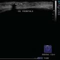
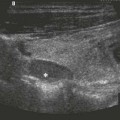
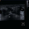
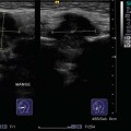
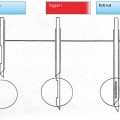
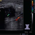
14 Image Processing Methods The use of advanced computer technology allows for manifold image processing methods which altogether facilitate the identification and evaluation of tissue alterations (Fig. 14.1). The field of view can be extended two-dimensionally—panoramic imaging—or three-dimensionally (3D) through image processing techniques. Elastic properties of tissue can be determined beyond the primarily visible (elastography) and, with the help of high-frequency ultrasound information (ultrasound RF, or radiofrequency, data), the user is able to undertake sonohistology (a statistical pattern analysis), detecting information that would not be detectable visually. Mathematical classification algorithms identify characteristic patterns and, with increasing experience, are able to recognize the patterns of specific tissues. The advantage of this procedure is its objectivity. In the following, some innovative procedures will be presented that were introduced to support tissue typing or that have potential as future routine applications. While the transducer is manually shifted in the scanning plane, a panoramic image is calculated from the individual overlapping images in real time without additional position detection (Fig. 14.2). The calculation is performed from one image to the next, first from two consecutively acquired images, then from the image calculated previously and the image acquired next. For this procedure, each image is subdivided into many small areas. In each section, characteristic properties are identified: These will be searched for in the following image to detect in what way the transducer was shifted and/or rotated. Then the new image will be added to the image already stored (Figs. 14.3, 14.4, 14.5). With this procedure a panoramic image with the high detail and contrast resolution of a single image and a maximum extent of up to 600 mm in length is generated. Different tissue structures can be distinguished more easily if documented in a single image. The panoramic image is particularly suitable for documenting complete findings, which would not be displayable in single images, and/or enabling a clearer visualization of adjacent structures (Fig. 14.6). In harmonic imaging (tissue harmonic imaging [THI]) the nonlinear parts (such as harmonics) of the ultrasound echo signals returning from the tissue are used for image generation (Fig. 14.7). The THI images appear to be higher in contrast than conventional images, since the tissue structures differ in their behavior with respect to pressure and negative pressure rather than in their acoustic impedance differences, which are the basis for conventional image generation (Fig. 14.8). At first, THI was a by-product of contrast-enhanced ultrasound: The principle of displaying harmonics only was developed to suppress tissue signals and display only contrast medium signals. It was then discovered that harmonics are also created when ultrasound propagates inside the tissue. Owing to the different sound wave velocities of the tissue with pressure and negative pressure, the sound wave deforms depending on tissue characteristics, and harmonic frequency parts are generated. These are utilized for image generation (THI). Ultrasound system manufacturers offer various methods of separating harmonics from fundamental waves. Basic systems work with high-pass filter technology (narrowband) whereas more advanced systems are equipped with subtraction filters and work with broadband technology (Fig. 14.9). The broadband visualization of the harmonic tissue properties through THI leads to particularly clear images free of artifacts (e.g., of the vascular walls; Fig. 14.10). Broadband harmonic imaging is able to separate harmonic from fundamental image signals in a particularly effective way. THI includes procedures such as phase inversion (PI) technology. With PI, two transmit pulses of equal shape but different phases (180° = inverted or inverted polarity) are transmitted from the same position of the body. The two ultrasound line echoes are received and digitally interpolated. On in-phase addition of these two line echoes, the unmodified echo parts cancel and echo modifications add up, so that the harmonic frequency parts are available (Fig. 14.11). THI is basically helpful for hard-to-scan patients and increases the rate of patients who can be finally diagnosed using ultrasound. THI can deliver particularly clear and artifact-free images (e.g., of the vascular walls or in the near field) and will help in assessing distal sound phenomena that are visualized better with the activated mode. However, in the near field, enhanced contrast will lead to a coarse-grained image that may not optimally display the ultrastructure of different tissues (Figs. 14.12, 14.13, 14.14, 14.15). Sectional images are acquired from different directions with spatial compounding procedures (Fig. 14.16). The resulting single images are composed into a geometrically correct single image. The advantages are that areas of similar tissue properties are displayed as a more homogeneous area; tissue differences are distinguished more clearly; and curved contours are enhanced and displayed with less angle dependence (compare Fig. 14.12 with Fig. 14.17). In most cases the result is visually more satisfying. One reason is that the speckle patterns generated by interferences in the tissue are different for different acquisition directions and are blurred in the overlay. The actual tissue structure information stays the same from different directions and adds up. As a result, the image appears smoother and with softer contours. The use of compounding imaging (CI) techniques has clearly proven itself for use in the near field of head and neck soft tissue, with or without THI, and therefore CI should be activated or used as a default preset (Figs. 14.18, 14.19). To acquire data in the three-dimensional dataset for reconstruction, the transducer is moved perpendicularly to the scan plane manually or automatically. The registered volume includes either the B-mode image only and/or the (color-coded) flow information. The calculated and reconstructed volume can be displayed three-dimensionally transparently or with surface rendering, or in maximum intensity projection (MIP) (Fig. 14.20). One advantage is the free selection of arbitrary view planes ( If the rate of the display per second of the 3D volumes is high enough to allow adequate tracking of the volume movement, this is referred to as 4D imaging. Here, time is the fourth dimension and frame sequences acquired in real time are created ( So far, applications of three-dimensional techniques have not gained acceptance in head and neck ultrasound scanning (Figs. 14.21, 14.22; Various procedures are applied for the visualization of contrast media (Table 14.1), including in particular interesting approaches for second-generation contrast media with low mechanical index (low-MI) imaging. The user wants to see the contrast medium in clear contrast to the tissue to be able to evaluate the wash-in and presence of the contrast medium. Initially, filter procedures were used to visualize the contrast medium. The property of contrast medium blisters of showing harmonic frequency vibrations (e.g., twice the excitation frequency: second harmonic) due to excitation by suitable base frequencies was exploited. These “vibration” frequencies are filtered out. With second-generation contrast media (low-MI), the separation of tissue and contrast medium signals can be substantially improved by using an optimized excitation sequence and sequentially different processing of the received echo signals. This can be done to a point at which the tissue signal is almost totally suppressed and only the contrast medium is visible. One of these special procedures is the contrast pulse sequence (CPS) procedure, which is based on the characteristic of the contrast medium blisters (in the excitation frequency band that also includes the base band, the fundamental frequency band) to respond to pressure differences in a nonlinear way. The signal detected through this procedure is the “nonlinear fundamental” signal. For the nonlinear fundamental signal the difference between tissue and contrast medium is approximately 30 dB higher than for the harmonic signal. This is the basis for the clearer separation of contrast medium and tissue, which means that the tissue can almost be suppressed. The procedure is based on the principle that a sequence of transmit pulses of different amplitudes and different phasing is transmitted for each ultrasound image line (Fig. 14.23; For receiving, procedures similar to phase inversion procedures are used (but taking into account amplitude and accurate phasing). In the head and neck region, contrast media are used to distinguish between nonperfused and insufficiently perfused masses and to visualize perfusion patterns/angioarchitecture, for example with lymph nodes and vascular diseases. Evaluation of bolus kinetics or the wash-out behavior of a contrast enhancer may also give information on the perfusion characteristics of a tissue region (Figs. 14.24, 14.25; Table 14.1 Contrast enhancement procedures
Panoramic Imaging
Harmonic Imaging; Tissue Harmonic Imaging
Broadband Harmonic Imaging, Phase Inversion Technique
Spatial Compounding
Three-dimensional Ultrasound Imaging: 3D Image, 4D Image
 Video 14.1). Moreover, three-dimensional representations illustrate topography and volume information.
 Videos 14.2, 14.3).
 Video 14.4). Improvement of reconstruction modules and real-time display might bring advantages in the near future, especially in the fields of education and patient information.
Ultrasound Contrast Enhancement
 Video 14.5). Here, too, high demands are put on the controllability of the large number of transmitters of the array elements.
 Video 14.6).
Filter, harmonic |
• Phase modulation, phase inversion (PI), wideband harmonic — Inverted pulses along a scan line |
• Power modulation (PM), harmonic — Amplitude modulation along a scan line |
• Autocorrelation — Power Doppler, harmonic |
• Stimulated acoustic emission (SAE) |
• Contrast pulse sequencing (CPS) — Simultaneous modulation of amplitude and phase |
“Contrast enhancement” can also be achieved easily using hydrogen peroxide and carefully injecting it into fistulas. The depth extension of ducts is improved in most cases (Figs. 14.26, 14.27).
Stay updated, free articles. Join our Telegram channel

Full access? Get Clinical Tree


