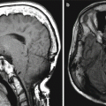
Fig. 12.1
MCA-STA bypass. The 3D MIP MRA (a) and 3D reformatted CTA image (b) show the superficial artery (arrows) entering the craniotomy and anastomosing with the prominent right superficial temporal artery (arrowheads) and M3 segment of the right middle cerebral artery
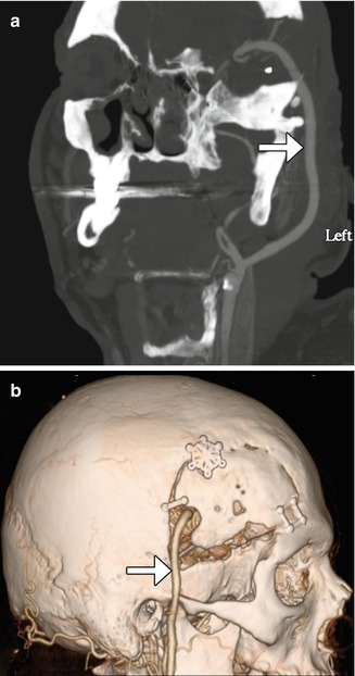
Fig. 12.2
EC-IC bypass with saphenous vein graft. Curved planar reformatted CT (a) and 3D CT (b) images show a large caliber saphenous vein graft (arrows) that connects the proximal ECA to the MCA
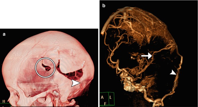
Fig 12.3
Occipital artery-MCA bypass. The patient has a history of failed left STA-MCA bypass. The 3D reformatted CTA image (a) shows the microcraniotomy (encircled) for the failed STA-MCA bypass and the left occipital artery (arrowhead) entering an additional craniotomy. The 3D reformatted CTA image (b) shows a patent anastomosis between the left occipital artery (arrowhead) and left middle cerebral artery (arrow)
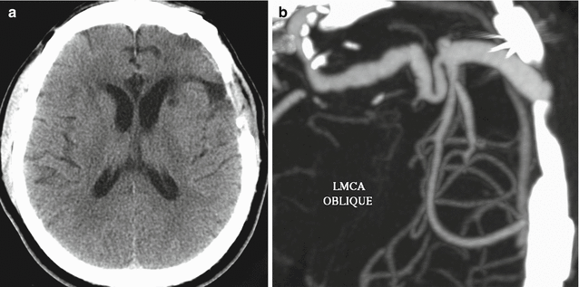
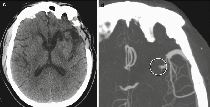
Fig. 12.4
EC-IC bypass occlusion. The patient has a history of complex left MCA aneurysm requiring left ICA occlusion and EC-IC bypass. Initial axial CT image (a) shows a small amount of encephalomalacia in the left temporal lobe and insula. The corresponding axial CTA MIP image (b) shows a patent bypass. Follow-up axial CT image (c) obtained 11 months later shows increased encephalomalacia. The corresponding axial CTA MIP image (d) now shows occlusion of the bypass near the anastomosis (encircled)
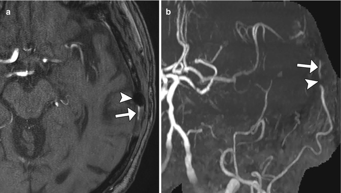
Fig. 12.5
Metal artifact simulating steno-occlusive disease of the STA-MCA bypass. Axial time-of-flight MRA image (a) shows susceptibility effect from a metallic clip (arrow) adjacent to the left superficial temporal artery branch (arrowhead). The corresponding MRA MIP image (b) shows focal loss of signal (arrow) along the course of the left superficial temporal artery, but there intact flow-related enhancement distally (arrow), indicating patency of the vessel
12.1.2 Indirect Extracranial-Intracranial Revascularization
12.1.2.1 Discussion
Indirect surgical revascularization can be performed as part of complex aneurysm obliteration and moyamoya disease primarily in adults. There are several methods for establishing indirect revascularization, including multiple burr holes, encephaloduromyosynangiosis, and encephaloduroarteriosynangiosis/pial synangiosis, among others.
Creating burr multiple holes (Fig. 12.6) can promote neovascularization to the brain surface. On post-contrast images, enhancement across the burr holes can be appreciated and ADC maps can show increased diffusivity. Depending on the particular technique, favorable results are achieved in nearly 90% of cases. However, in some cases, the delicate anastomoses may not provide sufficient revascularization, and cerebral infarction may result as the underlying disease process ensues.
Encephaloduroarteriomyosynangiosis (EDAMS) consists of creating a linear craniotomy, narrow dural opening, and placing temporalis muscle flaps directly upon the exposed pial surface to stimulate collateral development (Fig. 12.7). The superficial temporal artery and attached flap are then sutured to the dura. Alternatively, encephalomyosynangiosis (EMS) can be performed for increasing both intracranial and extracranial collateral circulation by inserting the temporal muscle deep to the craniotomy flap directly upon surface of the brain. During the early postoperative period, the swollen muscle can exert mild mass effect upon the underlying brain parenchyma (Fig. 12.8). Postoperative angiography reveals good revascularization in the majority of cases.
Encephaloduroarteriosynangiosis (EDAS)/pial synangiosis consists of creating a defect in the dura and arachnoid to enable direct suturing of the superficial temporal artery to the pia (Fig. 12.9). Following successful synangiosis, angiography shows progressive reduced flow in the moyamoya vessels and increase in size of the superficial temporal artery.
Angiography is well suited for monitoring the effects of synangiosis. Indeed, the angiographic findings of synangiosis are characteristic and include early filling of the middle cerebral artery branches via ECA injection, enlargement of the superficial temporal artery and middle meningeal artery, and the presence of transpial or transdural collateral vessels. Progression of proximal MCA or ICA stenosis is often apparent despite a successful surgical and clinical outcome, presumably due to diverted blood flow through the ECA circulation. In fact, the lack of MCA or ICA stenosis is associated with a relatively poor outcome. CT and MRI can be used to assess for complications, which include recurrence of ischemic events and chronic subdural hematomas.
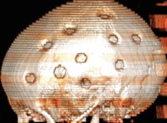
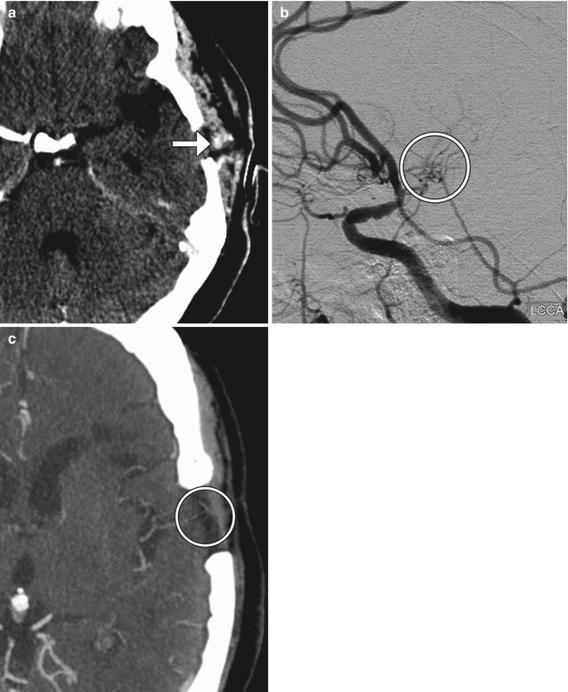
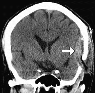
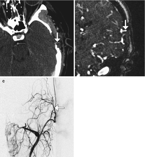
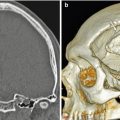
Fig. 12.6
Multiple burr holes for encephalogaleoperiosteal synangiosis. 3D CT image shows multiple left calvarial burr holes
Fig. 12.7
Encephaloduromyosynangiosis. The patient has a history of left MCA occlusion as well as right MCA and ACA stenosis. The patient was managed medically but recently developed repeated episodes of transient ischemic attacks to the left hemisphere. Consequently, an onlay external to internal carotid artery bypass with myosynangiosis was performed. Specifically, a direct anastomosis was not feasible due to lack of adequately patent cortical branches. Rather, the superficial temporal artery branch was placed over the brain surface along with its fascial cuff. This was done after multiple openings were made in the arachnoid to allow for percolation of cerebrospinal fluid. In addition, the temporalis muscle flaps were placed on the exposed brain surface to allow for additional synangiosis. Axial CTA image (a) performed shortly after surgery shows a left temporal microcraniotomy and temporalis muscle flap with a superficial temporal artery branch and fascial cuff (arrow) juxtaposed against the brain surface. Lateral digital subtraction angiography imaged obtained by injection through the left common carotid artery 3 months after surgery (b) demonstrates small collateral vessels (encircled) communicating between the intracranial and extracranial arteries. Axial CTA obtained 9 months after surgery (c) also shows formation of small collateral vessels (encircled) that bridge the temporal lobe cortex and temporalis muscle
Fig 12.8
Encephalomyosynangiosis. Coronal CT image obtained during the early postoperative period shows the left temporalis muscle (arrow) tunneled under the left craniotomy flap, where it exerts mild mass effect upon the brain parenchyma
Fig. 12.9
Encephaloduroarteriosynangiosis/pial synangiosis. Axial CTA image (a) and coronal (c) contrast-enhanced MRA image (b) show the left superficial temporal artery (arrows) passing through the small craniotomy defect to contact the pial surface of the brain. The prominent left superficial temporal artery (arrow) supplying the pial surface of the brain is also well depicted on the digital subtraction angiogram (c) from an external carotid artery injection
12.1.3 Intracranial Aneurysm Wrapping
12.1.3.1 Discussion
The concept of wrapping aneurysms with strips of muscle tissue was first introduced by Cushing as a treatment of ruptured aneurysms. The temporalis muscle is an accessible source of the necessary tissue. Alternatively, muslin has also been used as a wrapping material. Since the 1980s, the practice of wrapping aneurysms has declined in popularity. Nevertheless, muscle wrapping is still used as a last resort for treatment of aneurysms when endovascular stenting/embolization or surgical clipping is not feasible.
Following aneurysm wrapping surgery, the aneurysm will typically appear about the same size or perhaps slightly smaller, since the main goal of the procedure is to prevent further expansion. Although the muscle wrap itself is often inconspicuous, it should not be confused with tumor or other abnormalities, such as hemorrhage, on imaging (Fig. 12.10). However, the wrap can resorb and allow aneurysm expansion and bleeding. Other complications include infection or foreign body reaction, if synthetic materials are used. Thus, the role of imaging following aneurysm wrapping is to evaluate for integrity of the wrap, aneurysm expansion or hemorrhage, and abscess or muslinoma formation.
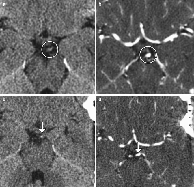
Fig. 12.10
Muscle wrap. The patient had a history of a growing left P1 segment aneurysm. Although aneurysm clipping was planned, muscle wrap was instead performed because clipping posed significant risk of occlusion of the thalamic perforator or constriction of the left P1 segment. Temporalis muscle was harvested. Preoperative axial CT (a) and CTA (b) images demonstrate an aneurysm arising from the posterosuperior aspect of the left P1 segment (encircled). Postoperative axial CT (c) and CTA (d) images show left temporal craniotomy and interval placement of the muscle wrap, which appears as soft tissue attenuation material surrounding the aneurysm and partially filling the left quadrigeminal plate cistern (arrows). The aneurysm is slightly less prominent than before surgery
12.1.4 Aneurysm Clipping and Hemostatic Ligation Clips
12.1.4.1 Discussion
Aneurysm clips are used to occlude the neck of aneurysms in order to prevent or cease hemorrhage due to rupture. These devices are available in a variety of shapes and sizes. They consist of a hinged wire with parallel ends that are straight or curved. In the past, aneurysm clips were composed of stainless steel or tungsten. Although these materials are biocompatible, they are not MRI compatible. These clips also produce considerable beam-hardening artifact that can obscure surrounding structures. Newer clips are composed of non-ferromagnetic materials, such as titanium, which are MRI compatible and produce fewer artifacts on CT.
Surgery for aneurysm clipping consists of performing a craniotomy. In addition, variable amounts of the anterior clinoid process may be resected in order to access paraclinoid aneurysms (Fig. 12.11). Deeply positioned aneurysms can be difficult to attain for clipping, which can result in aneurysm remnants. Incomplete clipping can present as increased hemorrhage shortly after clipping of ruptured aneurysms, for example, and can be addressed by endovascular embolization (Fig. 12.12). Although the brain can be retracted in order to maximize the field of view and access for centrally located aneurysms, vascular injury can result. Likewise, vessels adjacent to aneurysms that have poor visibility can be inadvertently clipped, such as the recurrent artery of Heubner, which can result in caudate infarcts (Fig. 12.13).
Vasospasm is a significant source of morbidity in patients with ruptured cerebral aneurysms and typically manifests 7–10 days after the episode of subarachnoid hemorrhage. Transcranial Doppler ultrasound is routinely used to assess for cerebral vasospasm, but the modality has limited sensitivity and specificity. CTA is also commonly implemented for the detection of cerebral vasospasm following subarachnoid hemorrhage and may demonstrate multifocal steno-occlusive lesions and areas of hemorrhage (Fig. 12.14). In addition, CT perfusion can be performed concurrently to provide insight into the extent of cerebral ischemia resulting from vasospasm. Unfortunately, streak artifact from the aneurysm clip can limit the assessment of the adjacent vasculature. Ultimately, catheter-based angiography has been considered to be the historical gold standard to diagnose vasospasm.
The incidence of recurrent aneurysms after complete clipping is approximately is low, but this complication can lead to subarachnoid hemorrhage and requires repeat clipping or endovascular intervention. It is also important to carefully search for new aneurysms on postoperative scans, since the annual rate of de novo aneurysm formation is about 0.9%. These occur on average at about 10 years after surgery. Thus, long-term angiographic follow-up is warranted in patients with clipped aneurysms.
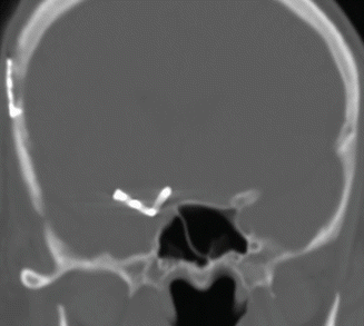
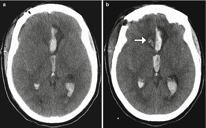
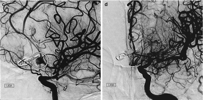
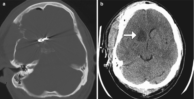
Fig. 12.11
Anterior clinoid process resection. Coronal CT image shows absence of the right anterior clinoid process and a right curved-tip aneurysm clip
Fig. 12.12
Incomplete aneurysm clipping. Axial CT image at initial presentation (a) shows hemorrhage into the left frontal lobe (arrow) and in the ventricular system due to aneurysm rupture. Axial CT image obtained shortly after anterior communicating artery aneurysm clipping (b) shows new hemorrhage in the right frontal lobe. Digital subtraction angiogram (c) shows residual filling of the aneurysm sac (encircled) adjacent to the clip. The residual aneurysm sac was then embolized (d)
Fig. 12.13
Adjacent vessel clipping. Axial CT images (a, b) show an anterior communicating artery clip and a recent right caudate infarct (arrow) due to recurrent artery of Heubner compromise
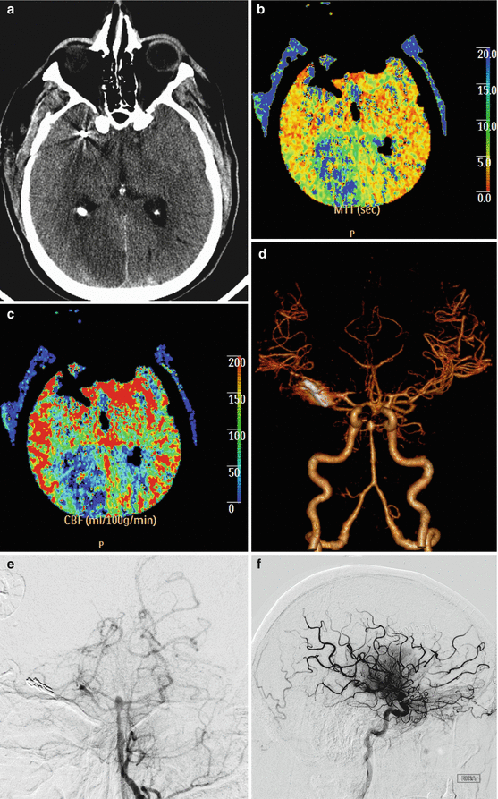
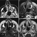
Fig. 12.14
Vasospasm. Axial CT image (a) obtained 1 week after clipping of a ruptured cerebral aneurysm shows areas of hypoattenuation in multiple vascular territories and scattered subarachnoid hemorrhage. The MTT (b) and CBF (c) maps show perfusion deficits in the bilateral anterior cerebral artery and right posterior cerebral artery territories. The CTA (d) and digital subtraction angiography images (e, f) show severe vasospasm in the anterior and posterior cerebral vessels, with relatively less pronounced involvement of the middle cerebral artery territories
12.1.5 Vascular Malformation Surgery
When possible, microsurgical resection is the optimal treatment option for arteriovenous malformations and cavernous malformations. While the nidus of the arteriovenous malformation represents the target of resection, the remaining draining vein can be clipped for hemostasis (Fig. 12.15). However, proximal ligation of the supplying arteries alone can make subsequent embolization more difficult and may rapidly lead to revascularization. For inoperable arteriovenous malformations that require treatment, stereotactic radiosurgery is an alternative. This treatment essentially results in thrombosis of the malformation. Further, sometimes radiation necrosis can result, which may appear as a peripherally enhancing lesion with surrounding vasogenic edema (Fig. 12.16).
With respect to cavernous malformations, developmental venous anomalies are often incidental findings that are not generally considered targets for treatment. However, seizure outcome after resection of cavernous malformations is better when surrounding hemosiderin-stained brain also is removed, although this can be challenging when critical structures are involved (Fig. 12.17).
Head and neck lymphatic malformations are often transspatial and are often not amenable to complete surgical resection. However, when lymphatic malformations compromise critical structures, such as the airway, partial resection may be performed. MRI is a suitable modality for accurate delineation of the residual tumor, which is useful for planning subsequent additional surgery or sclerotherapy if needed (Fig. 12.18). Obtaining up-to-date imaging is particularly relevant since the lesions often evolve spontaneously, with new and enlarging components.
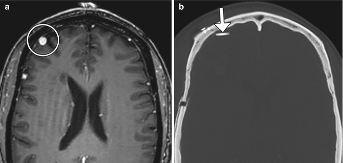
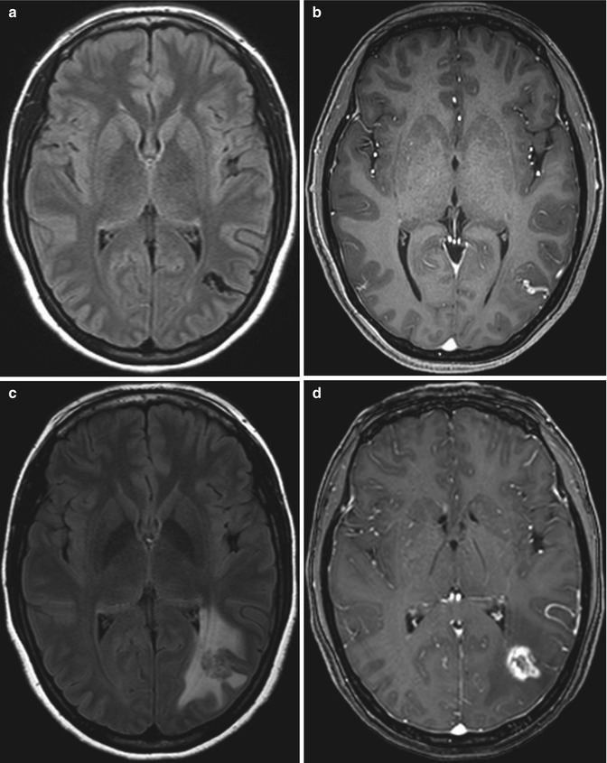
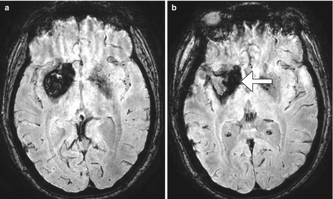
Fig 12.15
Arteriovenous malformation resection. The patient has a history of a right frontal lobe arteriovenous malformation. Preoperative axial post-contrast T1-weighted MRI (a) shows an enlarged draining right cortical vein (encircled). Postoperative axial CT image (b) shows a Weck clip (arrow) used to ligate the vein during surgery
Fig 12.16
Arteriovenous malformation stereotactic radiosurgery with radiation necrosis. Pretreatment axial FLAIR (a) and post-contrast T1-weighted (b) MR images show a left temporo-occipital nidus. Posttreatment FLAIR (c) and post-contrast T1-weighted (d) MR images show interval development of extensive vasogenic edema surrounding a peripherally enhancing lesion due to radiation necrosis at the site of the arteriovenous malformation, which is no longer apparent
Fig. 12.17
Residual hemosiderin staining after cavernous malformation surgery. Preoperative SWI MRI (a) shows a large right basal ganglia cavernous malformation. Postoperative SWI MRI (b) shows that the bulk of the cavernous malformation is no longer present, but there is abundant peripheral hemosiderin staining that remains (arrow)
Fig. 12.18
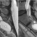
Partial resection of lymphatic malformation. Preoperative axial T2-weighted MRI (a) shows a transspatial macrocystic lesion with a component that obstructs the upper airway (arrow). Postoperative axial T2-weighted MRI (b) shows successful resection of the component of the lymphatic malformation that compromised the airway but interval appearance of an adjacent cystic component (*)
12.1.6 Microvascular Decompression/Jannetta Procedure
12.1.6.1 Discussion
Microvascular decompression can be used to effectively treat vascular loop syndromes, such as trigeminal neuralgia and glossopharyngeal neuralgia (Figs. 12.19, 12.20, and 12.21). The technique essentially consists of interposing Teflon between the affected nerve and the offending vessel. The concept behind this procedure is that the Teflon distances and redirects the transmitted pulsation of the adjacent artery away from the nerve. Teflon is hyperattenuating on CT and low signal intensity on all MRI sequences. High-resolution T2-weighted MRI sequences are particularly useful for analyzing the position of the pledgets and altered anatomy, which often entails distortion of the nerve course. During the early postoperative period, reversible elevated T2 signal and restricted diffusion is often observed in the ipsilateral pons after trigeminal decompression and does not necessarily indicate infarction. Perhaps the most common complication of microvascular decompression is recurrent symptoms related to suboptimal pledget positioning (Fig. 12.22). For example, in patients with persistent hemifacial spasm after microvascular decompression, residual vascular compression is most commonly encountered proximal to the pledget, along the attached segment of the nerve. Hearing loss is a more unusual complication that can result from Teflon migration or the use of excess Teflon that compresses cranial nerve 8 within the internal auditory canal (Fig. 12.23). Granulomas can occasionally form in reaction to the presence of Teflon, which forms a mass that has low T2 signal and enhances (Fig. 12.24).
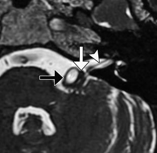
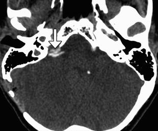
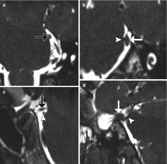
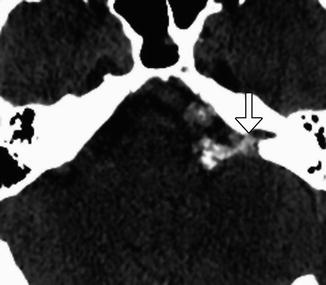
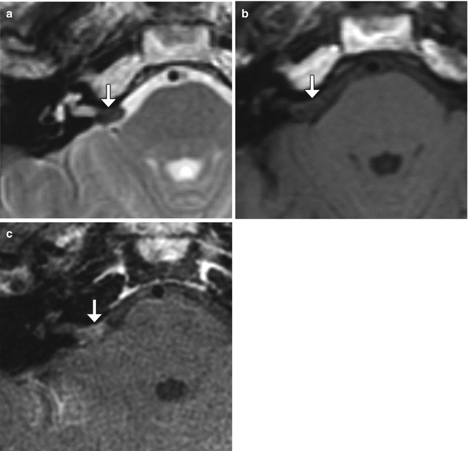
Fig. 12.19
Microvascular decompression for trigeminal neuralgia. Axial CT (a) and 3D time-of-flight MRA (b) show Teflon pledgets in the region of the bilateral trigeminal nerve root entry zones (arrows)
Fig. 12.20
Microvascular decompression for hemifacial spasm. Axial CISS MRI shows Teflon (white arrow) interposed between the left facial nerve (arrowhead) and the enlarged, tortuous basilar artery (black arrow)
Fig. 12.21
Microvascular decompression for glossopharyngeal neuralgia. Axial CT image shows pledgets (arrow) used to isolate the right glossopharyngeal nerve root entry zone from surrounding vessels
Fig. 12.22
Failed microvascular decompression. The patient presented with persistent symptoms of trigeminal neuralgia following attempted decompression. Coronal (a, b) and sagittal (c, d) CISS (thin section) MR images show that the pledget (black arrows) is positioned superior to the superior cerebellar artery (arrowheads), which directly contacts the left trigeminal nerve (white arrows)
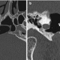
Fig. 12.23
Cochlear nerve compression after microvascular decompression. The patient presented with hearing loss after microvascular decompression via Teflon injection for hemifacial spasm. Axial CT image shows a large amount of Teflon in the left cerebellopontine angle, which enters the internal auditory canal (arrow), presumably compressing the cranial nerve 8
Fig. 12.24
Teflon granuloma. Axial T2-weighted MRI (a) shows a globular hypointense lesion in the right cerebellopontine angle cistern (arrow). Axial pre- (b) and post-contrast T1-weighted (c) MR images show corresponding mild enhancement of the lesion (arrows)
12.1.7 Carotid Endarterectomy
12.1.7.1 Discussion
Carotid endarterectomy (CEA) is considered the treatment of choice for symptomatic and asymptomatic patients with high-grade carotid artery stenosis. In order to appropriately interpret imaging studies obtained following CEA, it is helpful to be familiar with the surgical techniques involved.
CEA can be performed through an incision made anterior to the sternocleidomastoid and ligation of the facial vein in order to expose the carotid bifurcation and clamping of the carotid artery distal to the endarterectomy. Consequently, a small hematoma within or adjacent to the sternocleidomastoid and mild circumferential narrowing of the carotid artery resulting from clamp placement during surgery can be appreciated on follow-up CT (Fig. 12.25). These findings are usually self-limited.
CEA involves opening the carotid artery, removing the plaque and associated endothelium, and suturing the vessel wall closed with or without an enlargement patch. The patch is usually composed of Dacron, which is not readily visible on CT, but can appear as a thin hyperechoic mesh on ultrasound (Fig. 12.26). Alternatively, the section of carotid artery that is resected can be reconstructed using a saphenous vein graft. This has a distinct patulous or bulbous appearance on imaging (Fig. 12.27).
Complications related to CEA include localized intimal flap or dissection, reperfusion syndrome, patch infection, restenosis, cerebral infarction, and cranial nerve injury, usually facial and hypoglossal (Figs. 12.28, 12.29, 12.30, 12.31, 12.32, and 12.33).
Wound infection following carotid endarterectomy occurs in about 2% of cases. Staphylococcus species are the most common causative organisms. Patients typically present with wound swelling, drainage, and fever. On imaging, abscess appears as a fluid collection that abuts the surgical site. Characteristic rim enhancement and cellulitis are often present. There may also be debris, septations, and draining sinus that extends from the operative bed to the incision. Wound abscesses usually resolve with antibiotics and debridement. However, periarterial abscess or patch infection may predispose to dehiscence of the suture line, resulting in pseudoaneurysm formation.
Hyperperfusion or reperfusion syndrome is an unusual complication of carotid endarterectomy or carotid artery stenting, occurring in 0.3–1.2% of cases. A possible etiology for this condition is impaired cerebrovascular autoregulation. Predisposing factors include severe underlying cerebrovascular disease, diabetes mellitus, long-standing hypertension, prolonged cross clamping during endarterectomy, and a greater than 100% increase in the degree of reestablished cerebral blood flow, which is usually associated with greater than 90% carotid artery stenosis. Patients may present with headaches, seizures, focal neurological deficits, or confusion within several days after surgery. Patients may recover completely if the diagnosis is made promptly. However, in some series, there is a mortality rate of up to 50%. The diagnosis of cerebral hyperperfusion syndrome can be suggested on CT in the proper setting by noting the presence of edema, often in the watershed zones ipsilateral to the side of surgery. On MRI, focal ipsilateral vasogenic edema is apparent. Diffusion-weighted imaging and apparent diffusion coefficient maps help confirm the presence of vasogenic edema. On MRA, prominent vessels on the affected side may be apparent. Similarly, perfusion-weighted imaging can depict the relative increased flow to the affected side. The finding of hemorrhage portends a poor prognosis. Imaging can help identify hyperperfusion syndrome before serious sequelae result. Differential considerations for the imaging appearance of cerebral hyperperfusion syndrome include hypertensive encephalopathy, cyclosporine toxicity, and eclampsia. The lack of restricted diffusion helps exclude cerebral ischemia.
Recurrent stenosis after carotid endarterectomy occurs at the rate of about 1% per year. This complication is the main limitation of carotid endarterectomy and predisposes to cerebrovascular ischemia. Acute thrombotic occlusion is much less common and is a potentially devastating complication that can result in cerebral infection. Conventional carotid endarterectomy with patch angioplasty and the use of lipid-lowering pharmaceuticals are associated with lower rates of restenosis. Risk factors for restenosis include female gender and renal failure. CTA, MRA, and Doppler ultrasound are all appropriate for evaluation of suspected restenosis or occlusion after carotid endarterectomy. Each of these modalities has advantages and disadvantages. CTA with reformats, especially the curved planar reformats, is useful for studying stenoses. In the setting of carotid endarterectomy with patching, the internal carotid artery velocities on Doppler ultrasound must be interpreted with caution, since these are normally higher than in the nonoperated counterparts. MRA is best suited for identifying pseudo-occlusions.
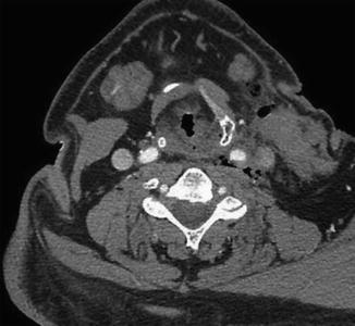
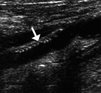
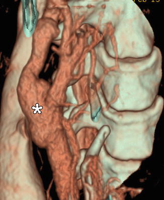
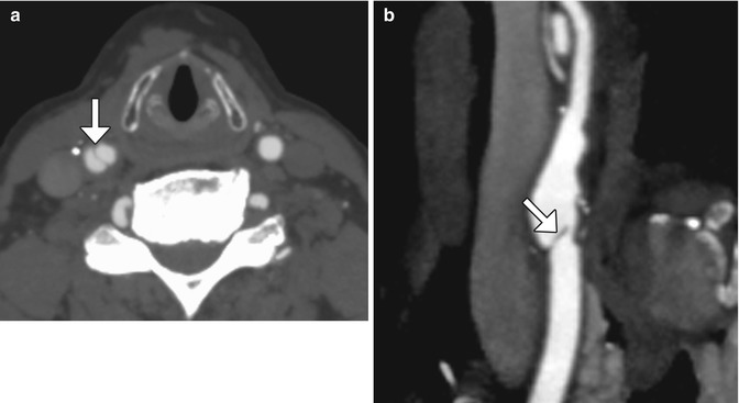
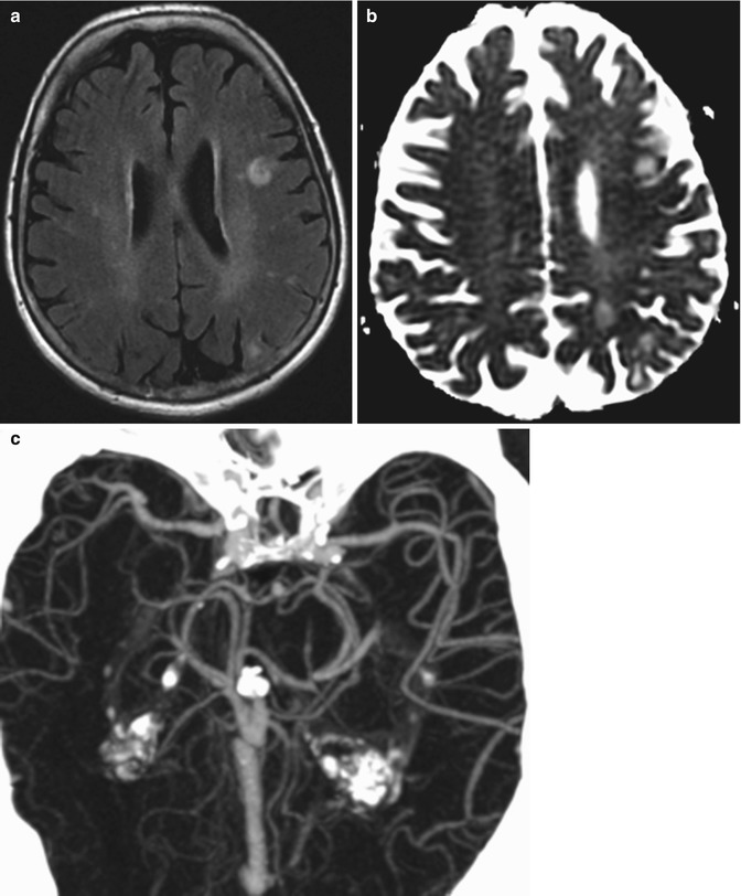
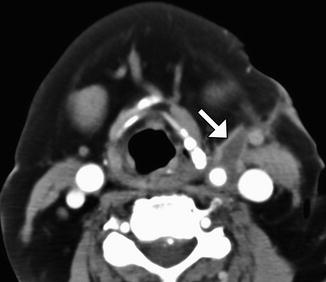
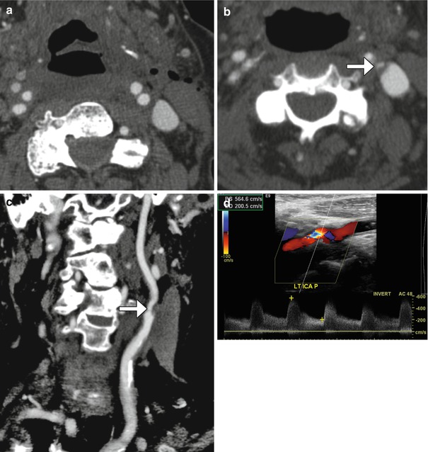
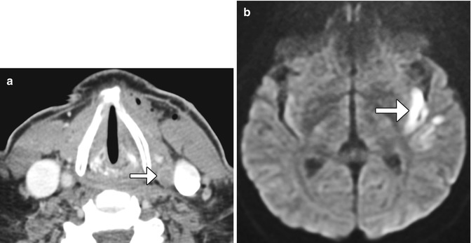
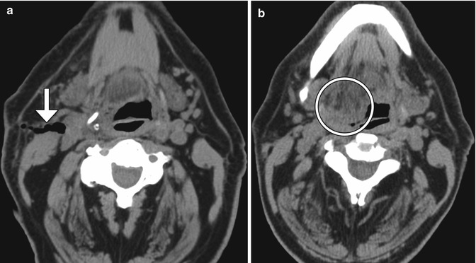
Fig. 12.25
Expected carotid endarterectomy early postoperative changes. Axial contrast CT after recent CEA demonstrates several foci of air scattered within and adjacent to the surgical bed, left sternocleidomastoid swelling, and edema in the fat planes
Fig. 12.26
Patch endarterectomy ultrasound image shows the echogenic Dacron patch (arrow) in the proximal internal carotid artery
Fig. 12.27
Endarterectomy with saphenous vein graft. 3D CT image shows a patulous reconstructed right carotid bifurcation (*)
Fig. 12.28
Localized intimal flap. Axial (a) and curved planar reformatted (b) CT images show a linear filling defect (arrows) at the junction of the endarterectomy patch and native carotid artery
Fig. 12.29
Reperfusion syndrome. The patient presented with acute onset of seizures 1 week status post left carotid endarterectomy. Axial FLAIR MRI (a) and ADC map (b) show areas of high T2 signal with elevated diffusivity in the left cerebral hemisphere watershed zones. CTA MIP image (c) shows asymmetrically prominent left middle cerebral artery branches diffusely
Fig. 12.30
Patch infection. The patient presented with fever, swelling, and purulent drainage from the left carotid endarterectomy incision site. Axial CT image shows a rim-enhancing fluid collection (arrow) surrounding the left carotid artery surgical bed
Fig. 12.31
Carotid artery restenosis. Initial postoperative axial CTA image (a) shows a patent proximal left internal carotid artery. Axial (b) and curved planar reformatted (c) CTA images obtained 6 months later now show focal high-grade stenosis at the origin of the left internal carotid artery due to low-density plaque at the site of reanastomosis (arrows). Doppler ultrasound (d) confirms the presence of high-grade stenosis of the proximal internal carotid artery with turbulent flow and velocities surpassing 500 cm/s
Fig. 12.32
Post-endarterectomy carotid artery occlusion and cerebral infarction. Delayed phase axial CTA image (a) shows occlusion of the CCA at the site of recent CEA (arrow). The diffusion-weighted image (b) shows an associated left internal capsule/insula infarction (arrow)
Fig. 12.33
Cranial nerve injury. The patient presented with right cranial nerve XII deficit after right internal carotid endarterectomy. Initial postoperative axial CT image (a) shows that the endarterectomy was performed at the expected level of the right hypoglossal nerve (arrow). A subsequent axial CT image (b) shows prolapse and fatty infiltration of the right hemi-tongue (encircled)
12.1.8 Carotid Body Stimulation
12.1.8.1 Discussion
Electrical stimulation of the carotid sinus can be used to treat systemic hypertension that is unresponsive to medical therapy. The phenomenon is effectuated by initiating the baroreceptor reflex and decreasing sympathetic tone. Implanted carotid sinus stimulation systems comprise a pulse generator and bilateral perivascular carotid sinus leads (Fig. 12.34). Insertion of these devices does not appear to cause carotid artery injury or other major side effects.
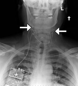
Fig. 12.34
Carotid body stimulator. Frontal radiograph shows a Rheos device with bilateral carotid sinus electrodes (arrows) and pulse generator in the right chest subcutaneous tissues (*)
12.1.9 Adjustable Vascular Clamp
12.1.9.1 Discussion
Adjustable vascular clamps were first introduced in the 1950s for treating carotid system aneurysms. Several varieties of metallic extracranial carotid vascular clamps have been developed, including the Selverstone, Crutchfield, Poppen-Blaylock, Salibi, and Kindt. The principle behind such vascular clamps is to reduce blood flow and to promote clotting of the aneurysm. If collateral circulation via the circle of Willis is inadequate, the clamps can be loosened. Gradual, graded occlusion of the carotids would yield better results than immediate occlusion. Over time, however, carotid revascularization can occur through the clamp and regular follow-up is recommended. On imaging, the clamps are recognized as rectangle-shaped metallic parts with central openings of variable sizes (Fig. 12.35). The lumen distal to the clamp becomes diffusely narrowed and usually remains as such even after the clamp is removed.
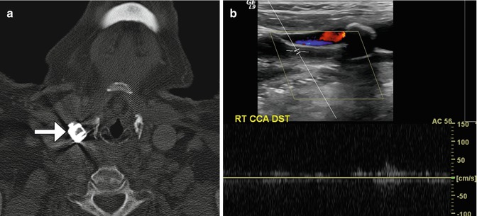
Fig. 12.35
Selverstone clamp. The patient has a history of right carotid body paraganglioma status post radiation and right common carotid artery aneurysm status post application of vascular clamp. Axial CT image (a) demonstrates a right common carotid artery clamp (arrow). Doppler ultrasound (b) shows paucity of flow in the common carotid artery distal to the clamp
12.1.10 Reconstruction of the Great Vessels
12.1.10.1 Discussion
Reconstruction of the great vessels may be performed for treatment of steno-occlusive lesions of congenital aberrations. The surgical maneuvers can be complicated and involve reimplantation of normal vessels onto others (Fig. 12.36) and/or the use of bypass grafts, such as collagen-impregnated Dacron and polytetrafluoroethylene (Figs. 12.37 and 12.38), each with different imaging appearing. Postoperative MRA, CTA, Doppler ultrasound, or catheter angiography can be used to evaluate suspected restenosis or occlusion (Fig. 12.39).
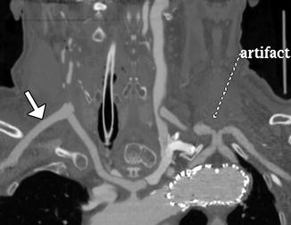
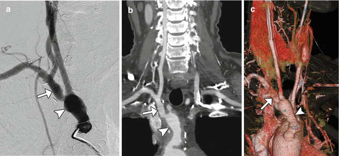
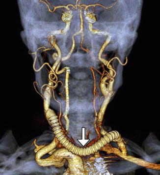
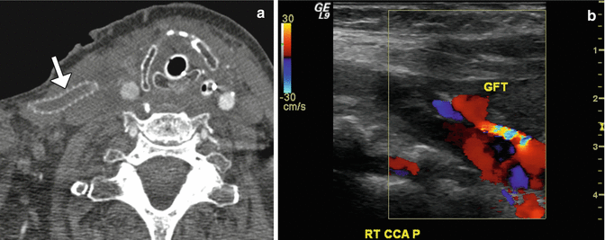
Fig. 12.36
Aberrant right subclavian artery reconstruction. Curved planar reformatted image shows a right axillary to right common carotid artery bypass (arrow) with retrograde opacification of the proximal axillary and distal right subclavian arteries. The proximal right subclavian artery has been sacrificed. There is also a left common carotid to subclavian artery bypass and an aortic endograft. There is artifactual duplication of the proximal left subclavian artery
Fig. 12.37
Dacron graft. The patient has a history of symptomatic right common carotid and innominate artery occlusive disease. The patient is status post recent aorta to right common carotid/right subclavian artery bypass from the ascending aorta utilizing a 10 mm Hemashield graft. The innominate artery underwent endarterectomy and end-to-end anastomosis with the 10 mm Hemashield, which in turn was anastomosed to the ascending aorta, also end to end. Catheter angiogram (a) shows a widely patent Hemashield graft (arrow) and distal vessels (arrowhead). CT angiography curved vessel trace (b) and 3D volume rendering (c) show patency of the aorta to right common carotid bypass components. The Hemashield graft (arrowheads) is a short bulbous segment connected to the stump of the innominate artery (arrows)
Fig. 12.38
Debranching of cerebral vessels, right-to-left common carotid artery crossover bypass, and left common carotid artery transposition to the left subclavian artery for treatment of thoracoabdominal aortic dissection. The 3D CTA reformatted image shows the cross-over polytetrafluoroethylene bypass graft (arrow)
Fig. 12.39
Thrombosed graft. The patient is status post aortic repair and subclavian injury followed by placement of a right carotid to axillary bypass graft with 6 mm externally supported polytetrafluoroethylene. Axial CTA image (a) shows lack of enhancement within the artificial graft (arrow), which is suggestive of thrombosis. There is also poor opacification of the distal right common carotid artery. Doppler ultrasound (b) of the distal graft anastomosis site reveals paucity of flow through the graft (GFT)
12.2 Endovascular Surgery
12.2.1 General Imaging Considerations Following Endovascular Cerebrovascular Procedures
Endovascular cerebrovascular procedures include endovascular reconstruction or deconstruction for cerebrovascular occlusive disease or active bleeding using stents or embolic material; embolization of tumors, aneurysms, or vascular malformations either preoperatively or for treatment; and mechanical or chemical thrombolysis for acute ischemic stroke or vasospasm. Materials that are typically used during neuroendovascular procedures include metal containing devices, such as coils, plugs, and stents, liquid embolic agents, balloons, and particles. Certain metals contained in some of these endovascular treatment modalities create substantial streak artifact on CT, rendering imaging less sensitive to vascular assessment. Most intracranial endovascular devices create relatively less artifact on MRI compared to CT. For example, embolic coils used in aneurysm are predominantly made of platinum. These have only mild susceptibility effect on MRI/MRA. Indeed, MRA is an effective means to assess small degrees of aneurysm recurrence following coil embolization (Fig. 12.40). Most intracranial stents have relatively low mass, but still produce susceptibility artifacts on MRI, giving the corresponding vessel’s intraluminal diameter a false appearance of being narrowed (Fig. 12.41). Liquid embolic agents, such as Onyx, generally produce a signal void on MRA, T1-, and T2-weighted MRI without significant obscuration of adjacent vasculature (Fig. 12.42). However, Onyx HD500 used for treating aneurysms is associated with more susceptibility effect compared to Onyx used for arteriovenous malformation embolization, which can overestimate the degree of stenosis on MRA (Fig. 12.43).
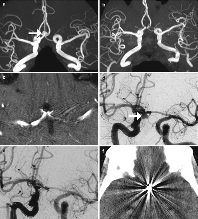
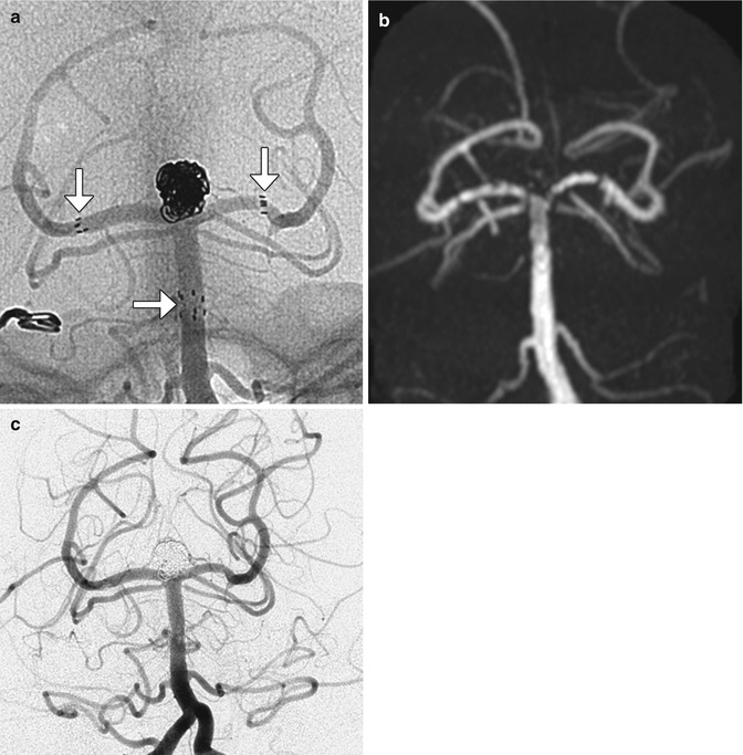
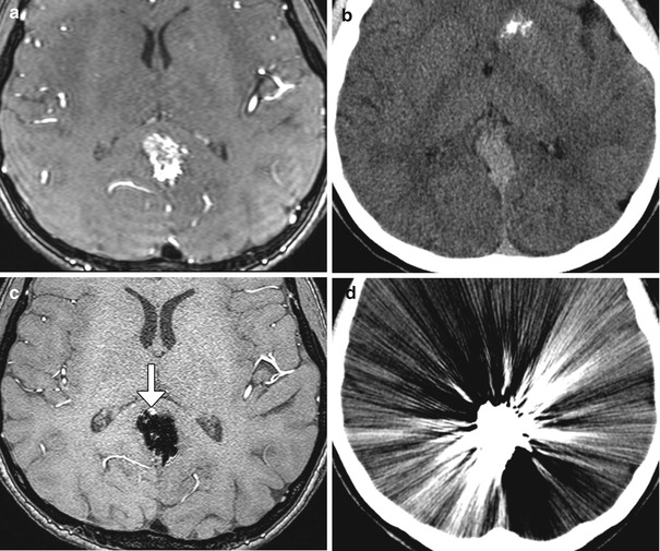
Fig. 12.40
Embolic coil occlusion. MRA before (a) and after (b, c) the anterior communicating artery aneurysm (arrows) demonstrate complete occlusion of the aneurysm, as demonstrated on pre- and post-embolization digital subtraction arteriograms (d, e). Axial CT image (f) following aneurysm embolization demonstrates substantial streak artifact which precludes evaluation for early recurrence as opposed to the MRA, which has negligible artifact, allowing for satisfactory evaluation of potential recurrence
Fig. 12.41
Stents. Unsubtracted angiographic image (a) following Y-shaped stent-assisted coiling of a basilar tip aneurysm demonstrates the proximal and distal markers (arrows) of the stents as well as coils within the aneurysm. MRA following the procedure (b) demonstrates occlusion of the aneurysm with artifact giving a false impression of stenosis along the stent despite lack of evidence for this on digital subtraction angiography (c)
Fig. 12.42
 Imaging of the Postoperative Skull Base and Cerebellopontine Angle
 Imaging of Cerebrospinal Fluid Shunts, Drains, and Diversion Techniques
 Imaging the Paranasal Sinuses and Nasal Cavity
 Imaging the Postoperative Scalp and Cranium
 Imaging of the Postoperative Ear and Temporal Bone
 Imaging of Postoperative Spine


Onyx liquid embolization. Time-of-flight MRA and CT before (a, b) and after (c, d) embolization of a posterior cingulate gyrus arteriovenous malformation using Onyx. Note that the embolic material creates significant artifact on CT preventing adequate evaluation, whereas time-of-flight MRA has the ability to detect a residual component of the arteriovenous malformation (arrow)
Related posts:
Imaging of the Postoperative Skull Base and Cerebellopontine Angle
Imaging of Cerebrospinal Fluid Shunts, Drains, and Diversion Techniques
Imaging the Paranasal Sinuses and Nasal Cavity
Imaging the Postoperative Scalp and Cranium
Imaging of the Postoperative Ear and Temporal Bone
Imaging of Postoperative Spine
Stay updated, free articles. Join our Telegram channel
Full access? Get Clinical Tree
