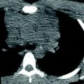
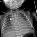
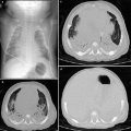
Fig. 1
Three projection images of the same 8-year-old child. a Upright PA view at 180 cm SID with fixed grid using DR; b Upright AP view 4 days prior at 180 cm SID with fixed grid using DR; and c Semierect, portable AP view at 100 cm SID without grid using CR
The lack of compliance in children has led to the development of specialized accommodations for immobilization during the examination. Immobilization devices are not completely radiolucent and cast shadows on the projected image (Fig. 2). Because some of the X-rays exiting the patient are attenuated by the device before reaching the image receptor, more X-rays must be used resulting in a small penalty in radiation dose to the patient.
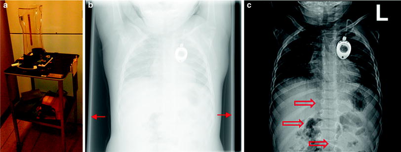

Fig. 2
Patient immobilization devices affect image quality and impose a dose penalty. a Pigg-O-Stat™ b unprocessed DR image showing edges of the holder (arrows) c for presentation image showing vertical artifacts (open arrows)
Because there was only one copy of the image, competition arose between physicians who wanted to use the information contained in the radiograph. For example, radiologists needed the image for primary interpretation while intensivists needed the image to monitor the condition of the patient and to provide immediate feedback on therapeutic procedures such as central venous line placement. This competition was resolved by two methods: copy film and double-loading. Upon developing the radiograph, the darkroom technician could immediately produce a copy film which was supplied to the intensivist. In this case, the radiologist would interpret the original radiograph, and the intensivist would have an image of compromised quality. An alternative method was double-loading of cassettes, that is, placing two sheets of film between the two fluorescent intensification screens to produce two radiographs from a single exposure. This practice led to two radiographs of compromised image quality, but satisfied the needs of two geographically dispersed observers. Neither method was optimal for both physicians. Both methods required additional materials and technologist time.
3 Digital Radiography
With the advent of computers and improvement in image distribution using networks, screen-film radiography has been largely supplanted by digital radiography. Digital images are available at multiple locations within a hospital network at the same time. Both the radiologist and the patient care provider can view the same study simultaneously at disparate locations. An extensive review of the technology and its application to chest radiography was published by Schaefer-Prokop et al. (2008).
Historically, digital radiography can be divided into two broad subtypes, computed radiography which requires a separate laser readout step and digital flat panel radiography which integrates the readout step into the imaging detector. These distinctions are blurred with the newer technologies. An alternative categorization divides digital radiography into “cassette-based” and “cassetteless” depending on the form-factor of the image receptor, irrespective of the image acquisition technology (Seibert 2007; Romlein 2007; Willis 2008).
3.1 Computed Radiography
Computed radiography (CR), also known as photo-stimulable phosphor (PSP) radiography, is based on the principle of photo-stimulable luminescence (PSL). A number of crystalline materials having some impurities that cause crystal defects, such as europium-doped barium fluorohalide, are able to store energy for an indeterminate period, and subsequently release that energy when exposed to light. The phenomenon has been known for centuries, but was only recently applied to imaging (Luckey 1975). An excellent review of CR has been published by Rowlands (2002). Coincident with the introduction of CR into clinical practice in the United States, the first reports of its use for radiographic imaging of the pediatric thorax are found (Kogutt et al. 1988; Cohen et al. 1989, 1991; Tarver et al. 1990; Merlo et al. 1991).
Three major film manufacturers competed to field CR products for clinical radiography. Oddly enough the original motivation was simply the manufacture of film. Suppose that a radiographic image could be captured on a single media, and the output to a single type of film. Since the image was digitized as an intermediate step in the process, it could be modified so that the resulting film image mimicked the image that would have been produced by any one of a dozen screen-film combinations. Multiple identical copies of the image could be printed, resolving the competition between the radiologist and patient caregiver for a single unique radiograph. It is important to understand that digital imaging was not originally intended to replace film, rather to make the manufacture of film more efficient and was likely to produce and sell more film!
The physical mechanism of PSL is not completely understood. The interaction of X-rays with the PSP material excites electrons, which can de-excite by prompt emission of light (fluorescence). Some of the excited electrons do not immediately give up their energy; instead they are trapped at a higher than normal energy state in local potential energy “wells” associated with defects in the crystal lattice (also known as “color centers”). The trapped electrons constitute the latent image. Over time the trapped electrons can escape on their own, but the fading of the stored signal is very gradual. When the PSP is exposed to light of a particular wavelength using a laser reader, the trapped electrons absorb enough energy to escape their traps and de-excite with the emission of visible light. The amount of emitted light is proportional to the original amount of X-ray exposure, so that it faithfully represents the projected X-ray shadow. The light can be collected and amplified by a photomultiplier tube and converted by an analog-to-digital converter into a digital value that is representative of the original X-ray exposure to the PSP. The original design of the laser readers was 90 s intended to compete with automatic film processor cycle time. The current generation of laser readers requires about 30–40 s to process the latent image.
3.2 Digital Flat-Panel Radiography
Digital radiography without the intermediate latent image and physical processing required by PSP-based radiography was first reported in the early 1980s. Scanned projection radiography was accomplished by means of a flying spot scanner that involved mechanical motion of a specially collimated X-ray generator and detector. The detector was a sodium iodide (NaI) scintillation crystal attached to a photomultiplier tube. Like CR, early application to pediatric chest radiography was reported almost simultaneously (Heller et al. 1982; Kushner 1983). Early reports also considered scanned linear arrays, such as the scout view of a Computed Tomography system as a means to generate a DR image of the chest.
Early DR systems relied on video cameras, and later charge-coupled device (CCD) arrays. Video cameras had very limited spatial resolution. CCD arrays have very small dimensions, therefore, a large field of view (FOV) must be minified somehow to conform to the small CCD array. This can be accomplished either by optical lenses or by tapered fiber optic bundles. Both of these methods have large losses in efficiency.
The amorphous silicon (a-Si) thin film transistor (TFT) array is the technology that made DR practical for medical imaging. The TFT array is bonded to the X-ray detector, eliminating the need for a separate reader step. Typical processing time is 10 s or less, much faster than CR. DR systems require some sort of X-ray conversion material. These flat-panel detectors are divided into indirect DR systems and direct DR systems based on the method of conversion. Indirect DR systems use an X-ray conversion layer, or scintillator, that converts X-rays into visible light by means of fluorescence. This is functionally similar to the intensification screen of the screen-film system, or to the input phosphor of an imaging intensifier for a fluoroscopy system. Gadolinium oxysulfide (Gd2O2S) and cesium iodide (CsI) are used in commercial indirect DR systems. Both of these materials convert X-rays into visible light. Visible light is easier to convert into an electronic signal (charge).
Direct DR systems use a thick amorphous selenium (a-Se) layer which converts X-rays directly into charge without the intermediate fluorescence step. High voltage across the amorphous selenium causes the charges (electron/hole pairs) that are created to migrate directly to the TFT elements where they are collected without lateral diffusion. This gives direct DR exceptional sharpness (spatial resolution). Direct DR systems are most often found in mammography applications.
4 Advanced Detector Technologies
4.1 Structured Phosphor
X-ray conversion layers differ in a fundamental way. Gd2O2S crystals are contained in a binder medium without any particular structure. On the other hand, CsI crystals are needles arranged parallel to each other (Fig. 3). This structure channels the fluorescence within each crystal toward the TFT array and discourages lateral diffusion of the light. For this reason, indirect DR systems that use CsI are expected to have better sharpness than those that use Gd2O2S. Alternatively, CsI conversion layers can be designed to provide better efficiency than Gd2O2S with the same sharpness, simply by making them thicker.
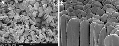

Fig. 3
Photomicrographs of unstructured and structured phosphors. a unstructured or powder phosphor. Gadolinium oxysulfide (GOS; Gd2O2S) is used in DR and barium fluorobromide (BaFBr) is used in CR. b structured or needle phosphor. Cesium iodide (CsI) is used in DR and cesium bromide (CsBr) is used in CR. Courtesy of AGFA Healthcare
The same principle can be applied to CR. Photo-stimulable phosphor materials are typically crystals contained in a binder without any organized structure. However, cesium bromide (CsBr) crystals can be made into an organized structure like CsI, and can also be doped to produce photo-stimulated luminescence (Leblans et al. 2000). The CsBr structured phosphor has the same advantages as CsI for restricted lateral diffusion of light over unstructured phosphors.
4.2 Slot Scanner
Scattered radiation degrades contrast in projection radiography. The anti-scatter grid is a well-known countermeasure, but has a penalty in requiring more X-ray exposure to get the same signal at the image receptor, with a corresponding increase in patient radiation dose. The amount of scattered radiation depends on the volume of tissue in the X-ray field—even for small patients this volume can be substantial when the entire image receptor is exposed at once. The mechanical slot-scanner moves a fan-shaped beam of X-rays across the FOV. In this way, a smaller volume of tissue is irradiated at one time, and the amount of scattered radiation is much less. This reduction in scatter is achieved without any dose penalty to the patient.
Slot scanners have shown significantly reduced scatter fraction compared with anti-scatter grids (Samei et al. 2004; Liu et al. 2008) and have shown some improved detection of simulated nodules and interstitial lung pathology in phantom testing (Kroft et al. 2004, 2005) but there is no information on use in clinical pediatric chest imaging.
4.3 Dual-Sided CR
The light from PSL is emitted in all directions. Conventional CR scanner designs collect light from the same side of the imaging plate that is stimulated by the laser, collecting at best only one-half of the PSL that is emitted. If the phosphor material is coated onto a translucent base, then it is possible to collect PSL from the back side of the imaging plate as well. Combining the signal collected from the back with the signal from the front improves the efficiency of detection with a small penalty in sharpness. Uffmann et al. (2005) reported improvement in the detection of simulated nodules using dual-sided CR compared to single-sided CR.
4.4 Irradiation Side Sampling Digital Flat Panel
This flat panel detector is designed so that the X-ray beam exiting the patient passes through the TFT array before reaching the CsI X-ray conversion layer. The TFT array is relatively radio-transparent, so there is little loss of signal. The majority of X-ray interactions generate fluorescence closer to the TFT array, so that there is less unsharpness from spreading of the light. In addition, the CsI crystals are grown on a substrate and then reversed and optically coupled to the TFT array. In this way, the fluorescence exits the top of the crystals, instead of the base of the crystals so that there is less diffusion of light from needle-to-needle. This detector is intended to produce better spatial resolution than conventional indirect DR designs.
4.5 Gaseous/Avalanche Detectors
A novel xenon (Xe) high-pressure (6 atm) gas-filled detector has been incorporated into a commercial imaging product primarily intended for orthopedic imaging. The detector has a high voltage electrode and an antenna array that amplifies photoelectrons produced from interactions with the X-ray beam into an avalanche that is collected by printed microstrips. The imaging system incorporates two of these detectors each paired with an X-ray tube collimated into a fan beam. The two fan beam/detector pairs are oriented orthogonally to each other. The subject stands upright in the imaging system and the fan beam/detector pairs descend from their highest extent to scan the patient simultaneously in the PA/AP and lateral orientation. The images are created line-by-line.
Commercial gas/avalanche slot scanners have been used for scoliosis examinations with a reduction in skin dose by a factor of 6–9 over CR systems with improved subjective image quality ratings (Deschenes et al. 2010; Despres et al. 2005). The time required to scan the thorax is 4–5 s, which may limit its utility for pediatric chest radiography, considering the potential for body motion, breathing, and multiple cardiac cycles during acquisition.
5 Digital Image Processing
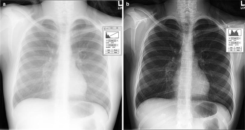
The principal advantage of the digital image compared to the conventional radiograph is the ability for multiple caregivers simultaneously to view the study in disparate locations. In addition to the advantage of availability, the digital image can be modified from its original state creating an infinite variety of possible presentations. In fact, modification of the original digital image is not just a cosmetic enhancement; this is absolutely required in order to render it usable for clinical diagnosis. By changing processing, one can enhance the image to identify abnormalities such as pneumothorax or highlight catheter placement.
A plethora of schemes and brand names exist for digital image processing. These are often cited by sales personnel as basis for differentiation among products. Irrespective of the specific method of acquisition, functional categories of image processing can be identified.
5.1 Preprocessing
Preprocessing (sometimes called “pre-acquisition processing”) involves corrections that are applied to the raw digital data. These include, in the case of CR and linear scan systems, corrections for nonuniform light collection efficiency in one dimension across the image receptor, and in the case of DR and other two-dimensional fixed array systems, corrections for gain, and offset nonuniformity among individual detector elements and amplifiers as well as correction of nonfunctional (“dead”) detector elements (Fig. 4).
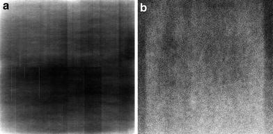

Fig. 4
Flat field DR images. a uncorrected and b corrected for gain and offset. Proper calibration corrects for unequal gain among detector elements (dels) and for nonfunctional dels
Preprocessing may also include rescaling of the numerical values of the digital data so that they bear a particular mathematical relationship to the X-ray exposure that produced them. For example, the raw data may have a linear relationship to the X-ray exposure and preprocessing may transform them so that they are linear with respect to the logarithm of exposure. Preprocessing is applied automatically according to data gathered during calibration protocols. Preprocessing is generally transparent to the radiologist, unless there is an error in the calibration. The digital image that results from preprocessing is called the “original data” in IEC terminology, “for-processing data” in DICOM terminology, and may be called “raw, ranged data” for some systems that incorporate auto-ranging in their preprocessing (Fig. 5).

