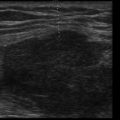
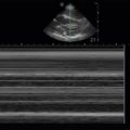
Key Points
- •
The inferior vena cava (IVC) is readily visualized using point-of-care ultrasound and can guide fluid management decisions, especially when taken in context of cardiac and lung findings.
- •
Correct interpretation of the IVC findings requires a thorough understanding of hemodynamics and respiratory physiology.
- •
Patients with cardiac tamponade will have a plethoric, dilated IVC, and absence of this finding can rapidly rule out tamponade in patients with a pericardial effusion.
Background
Point-of-care ultrasound examination of the inferior vena cava (IVC) offers a rapid, noninvasive determination of right atrial pressure to guide assessment of volume status and volume responsiveness. Image acquisition and interpretation can be mastered after brief, focused training, and various training protocols have been studied in providers from diverse medical specialties. Despite relative ease in image acquisition, interpreting IVC findings requires integration of a number of patient factors before incorporating findings into clinical decision making.
Anatomy
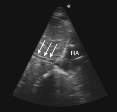
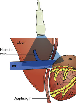
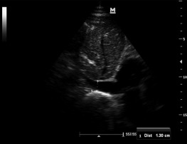
The IVC is located to the right of the abdominal aorta, and most of the IVC lies in the retroperitoneal space. Between the diaphragm and right atrium, the IVC has a very short intrathoracic segment ( Figure 18.1 ). From the subcostal cardiac window, the IVC appears as a large, intrahepatic vessel with thin walls, and under normal conditions typically demonstrates respirophasic variations in caliber ( Figure 18.2 and ![]() ). The IVC is a capacitance vessel and thus is sensitive to changes in right atrial pressure and volume status. In spontaneously breathing patients, where the intrathoracic pressure becomes negative during inspiration, the normal response to inspiration is a decrease of IVC diameter ( Figure 18.3 ). In patients on positive-pressure ventilation, the respirophasic change of the IVC is reversed with inspiration causing IVC distention. IVC size may also be influenced by venous return from the splanchnic circulation, diaphragmatic excursions during breathing, and intra-abdominal pressure.
). The IVC is a capacitance vessel and thus is sensitive to changes in right atrial pressure and volume status. In spontaneously breathing patients, where the intrathoracic pressure becomes negative during inspiration, the normal response to inspiration is a decrease of IVC diameter ( Figure 18.3 ). In patients on positive-pressure ventilation, the respirophasic change of the IVC is reversed with inspiration causing IVC distention. IVC size may also be influenced by venous return from the splanchnic circulation, diaphragmatic excursions during breathing, and intra-abdominal pressure.
Indications and Applications
The IVC is commonly assessed with ultrasound and has many potential applications at the point of care. The most common indications to assess the IVC with ultrasound are summarized in Table 18.1 .
| Indication | Notes |
|---|---|
| Volume responsiveness | Most reliable in ventilated patients |
| Central venous pressure | Approximations in spontaneously breathing patients |
| Pericardial effusion | Nondilated IVC can rule out tamponade physiology |
| Right heart failure | Dilated IVC seen in cor pulmonale, severe tricuspid regurgitation |
Excessive volume expansion is associated with worse outcomes in critically ill patients, making the identification of those who will benefit from volume—those who will see a meaningful increase (typically 15%) in cardiac output in response to a modest fluid bolus (typically 500 mL of crystalloid), also called volume responders—of great interest. The question of volume responsiveness has been extensively studied using IVC examination. The size and variation of IVC caliber throughout the respiratory cycle form the basis of most IVC assessments and represents a complex set of interactions that are most reliable in highly controlled circumstances, namely with mechanically ventilated, deeply sedated patients (see “Image Interpretation ” below). Ultrasound exam of the IVC in spontaneously breathing patients may be clinically useful, especially when assessed for extremes of size (flat vs. plethoric).
IVC ultrasound may be used to approximate invasive hemodynamic parameters, including central venous pressure (CVP). Although there is established correlation between CVP and IVC findings, CVP has not been shown to be predictive of volume responsiveness, despite the frequent use of CVP in many clinical settings and international sepsis guidelines.
Cardiac tamponade has several associated ultrasound findings that are reliable but require considerable experience to accurately recognize (see Chapter 17, Pericardial Effusion ). A simple measure to determine whether tamponade physiology is present can be performed by assessing the IVC. When tamponade is present, intrapericardial pressure must, by definition, be in excess of right-sided filling pressures, which creates congestion and dilation in the neighboring IVC.
IVC size and collapsibility may also guide fluid removal parameters in those undergoing chronic hemodialysis or with acute decompensated heart failure. IVC findings may help determine if fluid removal has been adequate and may be a useful adjunct to the patient’s dry weight.
Image Acquisition
In adults, any low-frequency transducer may be used, including a phased-array, curvilinear, or micro-convex transducer, but the IVC is generally imaged with a phased-array transducer. Two techniques to image the IVC have been described.
- 1.
Subcostal cardiac window
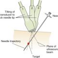
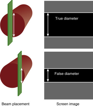
A long-axis view of the IVC at the right atrial junction from the subcostal window is the recommended view based on reliability and reproducibility (see Chapter 13, Cardiac Ultrasound Technique ). A phased-array transducer is placed in the subcostal window with the transducer marker pointing toward the patient’s head ( Figure 18.4 ). When the IVC is difficult to identify, a helpful strategy is to start with a subcostal 4-chamber view focusing on the right atrium (RA) and then rotate the transducer counterclockwise, aligning the ultrasound beam along the course of the IVC. An ideal long-axis view of the IVC shows the IVC entering the right atrium and a segment of the hepatic vein joining the IVC. Identifying both the RA-IVC junction and hepatic vein helps to avoid mistaking the IVC for the neighboring abdominal aorta. The pulsatile, thicker-walled abdominal aorta can be visualized by tilting the transducer medially. It is imperative to visualize the IVC longitudinally with the transducer centered on the long axis to assess the true diameter accurately. Off-axis imaging generates an oblique view of the vessel, resulting in a falsely small diameter, the so-called “cylinder effect” ( Figure 18.5 ). In general, once a long-axis view of the IVC with the RA-IVC junction and hepatic vein is visualized, fine rotation of the transducer helps to capture the true diameter.
- 2.
Transhepatic coronal view
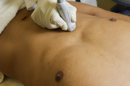
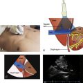
The liver parenchyma provides an excellent acoustic window and may be used when a subcostal view of the IVC is not obtainable (e.g., pregnancy, postoperative wounds or dressings, patient discomfort). The transducer is placed on the mid-axillary line with the transducer orientation marker pointed cephalad. Tilting the transducer with the ultrasound beam aimed posteriorly captures a long-axis view of the IVC passing through the liver and diaphragm. The aorta is seen posterior to the IVC in this view ( Figures 18.6 and 18.7 and ![]() ).
).

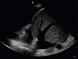
Image Interpretation
Interpretation of IVC images varies depending on the clinical scenario. The three most common clinical questions that IVC ultrasound can address are:
- 1.
Volume responsiveness
- 2.
Tamponade physiology
- 3.
CVP estimation
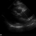
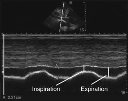
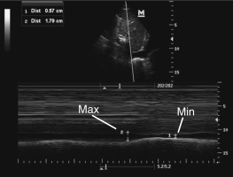
If choosing to quantitatively measure the IVC or changes with respiration, the image may be frozen and calipers can be used to measure the diameter perpendicular to the long axis of the vein approximately 2 cm from the RA-IVC junction. Once the largest diameter is measured, the cine function can be used, or a second image can be captured, to measure the smallest IVC diameter. Measurements should be taken in an identical manner. M-mode can also be used to measure IVC diameter and respirophasic variation ( Figure 18.8 ).
Volume Responsiveness
When assessing for volume responsiveness, it is essential to account for the ventilatory status of the patient, which can be broadly classified as:
- 1.
Spontaneous ventilation—breathing spontaneously with or without the help of an invasive or noninvasive ventilator
- 2.
Passive ventilation— mechanically ventilated with no spontaneous breaths
Spontaneous Ventilation
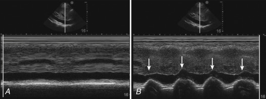
Changes in intrathoracic pressure during spontaneous breathing are transmitted to the IVC. Regardless of whether the patient is spontaneously breathing on or off a ventilator, the negative pressure from each breath differs, leading to variable loading conditions and consequently variable changes in IVC diameter ( Figure 18.9 ). Thus, the most reasonable approach in spontaneously breathing patients is to consider IVC diameter and collapsibility an indirect measure of CVP ( Table 18.2 ). Though evidence is limited to support CVP as a guide to fluid management, elevated CVP has been shown to be associated with a poorer response to fluid resuscitation; thus it is reasonable for a spontaneously breathing hypotensive patient (without right heart failure) with a dilated, noncollapsing IVC to be considered volume replete, and adjunctive therapies to fluid resuscitation should be considered, such as vasopressors. In all other scenarios of spontaneously breathing patients (e.g., noninvasive ventilation or triggering an invasive ventilator), IVC findings should be interpreted in conjunction with other clinical and ultrasound findings, including LV systolic function and lung–pleural profile, to assess total body and intravascular volume status.
| IVC Diameter and Collapse (%) | Central Venous Pressure (mean) (mm Hg) |
|---|---|
| Normal: ≤2.1 and >50% | 0–5 (mean 3) |
| IVC findings other than those seen with normal or high | 5–10 (mean 8) |
| High: >2.1 and <50% | 10–20 (mean 15) |
Passive Ventilation
The strongest correlation of IVC findings to determine volume responsiveness has been demonstrated with patients who are completely passive on a ventilator because the loading conditions of each breath are regulated by the ventilator ; however, a minority of patients in most critical care environments are sedated to the point of passive ventilation.
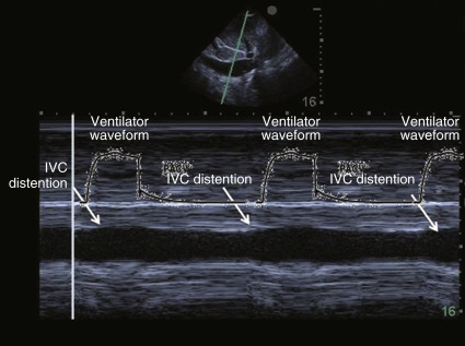
In this population, two well-designed studies demonstrated that IVC distention of at least 12% (IVC max − IVC min /IVC mean ) or 18% (IVC max − IVC min /IVC min ) in response to ventilator-delivered breaths was predictive of volume responsiveness. When interpreting respiratory variation of the IVC in this population, distention may be subtle on two-dimensional imaging. Thus, M-mode is recommended to capture these subtle changes ( Figure 18.10 and ![]() ).
).
The quality of evidence to determine volume responsiveness with IVC changes is less clear in patients who are triggering the ventilator or spontaneously breathing, and the accuracy of the 12–18% cutoffs is unknown.
When the IVC is small (<1 cm diameter), it is intuitive to use absolute IVC size independent of respirophasic changes to direct volume administration ( Figure 18.11 and ![]() ). A completely collapsed IVC, or “virtual” IVC, is almost certainly associated with volume responsiveness, although studies have not addressed this finding in particular.
). A completely collapsed IVC, or “virtual” IVC, is almost certainly associated with volume responsiveness, although studies have not addressed this finding in particular.

