Intrinsic parameters
Camera calibration
Focal length
f c
Optical center in the image plane
c c
Distortion parameters (radial and tangential)
k c
Extrinsic parameters
Hand-eye calibration
Orientation w.r.t. world coordinate system
R
Translation w.r.t. world coordinate system
t
Extrinsic Parameters
Endoscopes are often tracked using external tracking systems to report the camera’s position and orientation in the operating room’s coordinate system. Figure 30.1 depicts all involved components. Therefore, it is required to estimate the geometric relationship between the camera’s internal coordinate system (defined by the optical axis) and the tracking system. This transformation between camera and attached marker is computed by establishing the necessary 2D/3D correspondences in the two respective coordinate systems. This can be done by a tracked pen-probe where the tip of the probe needs to be positioned on predefined points that can also be seen with the camera, as in [100]. However, this manual procedure is very time consuming and error-prone. The robotics community was faced with a very similar problem where they had to estimate the transformation between a robot’s end effector and a camera attached to it. Several algorithms for solving this problem – known as hand-eye calibration – have been presented [22, 24, 94, 120]. An extensive comparison of these methods for calibrating a camera with a tracker has been presented in [7].
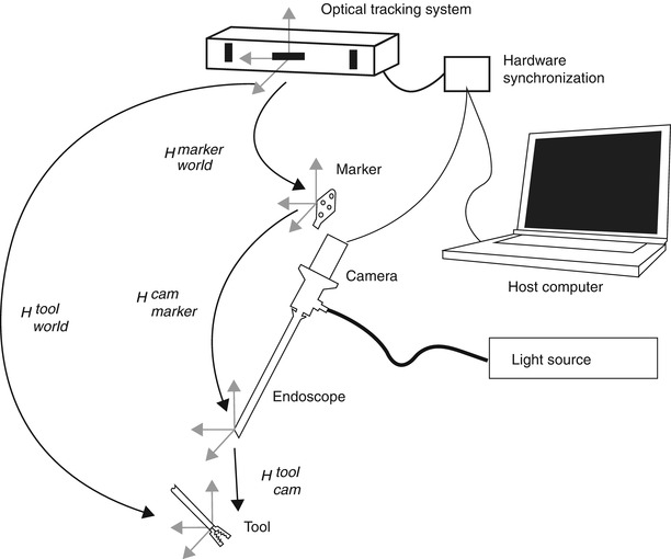
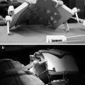
Fig. 30.1
Overview of the endoscopic 3D model acquisition system, depicting all involved components. H A B denotes the transformation between the respective coordinate system of components A and B
3D Model Reconstruction
Reconstructing 3D geometries from 2D images is an active field of research and has been widely applied in several areas. Typical applications include recreating architectural, archaeological, and more recently large-scale urban scenes.
Methods for reconstructing 3D models from 2D imaging devices include multiple view geometry [97], matrix factorization methods [66, 116], structured light [125], stereo vision [86], and time-of-flight cameras [72]. Extensions to handle multiple objects were presented in [41, 51], and [130].
Most of these techniques have also been applied for specifically reconstructing the surgical scene from endoscopic video streams: Multiple view geometry has been employed in [127], shape from shading in [26, 44], stereo cameras in [85], structured light in [56], and time-of-flight cameras in [95].
Methods relying on monocular endoscopes (multiple view geometry or shape from shading) offer the advantage that they can be used with the existing equipment and do not require any special equipment which may not be available in every operating room. For this reason and for a better understanding of the rest of this chapter, the multiple view geometry is further elaborated in the following section.
Multiple View Geometry
Multiple view geometry relies on at least two 2D images for reconstructing a 3D scene. Figure 30.2 illustrates the correspondences and geometry between a 3D point X and its 2D projections x and x′ in two images taken at different viewpoints. Mathematically, this can be expressed with the epipolar geometry which describes the projective geometrical relation between two views. It only depends on the camera’s internal parameters and relative pose, not of the imaged scene or its structure (as can be seen in Fig. 30.2). The epipolar geometry can be represented using a 3 × 3 matrix, called the fundamental matrix F, the epipoles e and e′ and the corresponding epipolar lines l and l′. For the special case of calibrated cameras (known intrinsic parameters), the essential matrix E can be derived. The concept of the epipolar geometry can be extended to three (trifocal tensor T [118]) and even to n views resulting in the n-focal tensor. However, this has seen very little practical use up to now. For more in-depth information about the epipolar geometry, the reader is referred to the literature [55].
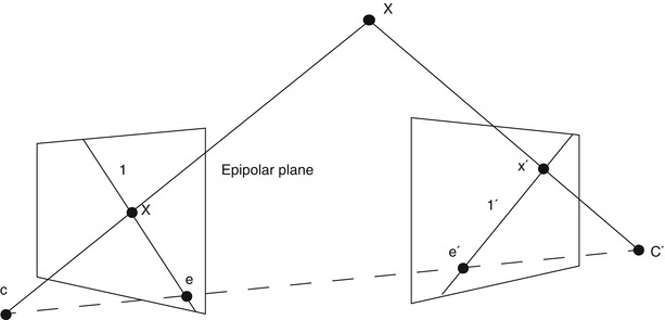
Fig. 30.2
Schematic view, illustrating the reconstruction of the position of a point X in 3D space from its projections (x and x′) onto the image planes of two cameras. The epipolar geometry of the stereoscopic camera setup is characterized by the projection centers of the cameras (C and C′), the epipolar line connecting them and the epipoles (e and e′), the intersection of the image planes with the baseline of the camera system
Establishing the correspondences across image sequences is not only a crucial step for 3D reconstruction but also plays a decisive role in other applications like referencing, navigation, and augmented reality.
Most often, basic primitives such as points and lines are used to find corresponding structures in the image sequence. In general, as no straight lines are visible in a surgical scene, point primitives are the best choice for this application. Finding accurately and robustly identifiable points (often called interest points) across several images is an active field of research with many advances currently being made.
Early interest point detectors such as the Moravec corner detector [82], the Harris and Stephens operator [53], the Kanade-Tomasi method [104, 117], and the SUSAN corner detector [107] were not dealing with variations of feature appearance across images, such as scale changes or rotations. Thus, they are not suitable for endoscopic interventions where the scale of the scene can change dramatically. For handling such variations, scale-space theory was introduced, providing a framework for representing the signals in a multi-scale fashion. The level curve curvature approach presented by [10] was the first to introduce automatic scale selection for coping with large-scale variations in the image domain.
An extension of the Harris operator with automatic scale selection was presented in [3, 74]. Detectors such as the Laplacian of Gaussian, the Difference of Gaussians (an approximation of the Laplacian), and the Determinant of the Hessian are usually called blob detectors, as they additionally provide local information about the region around the interest points. Interest points computed from the multi-scale Harris detector are invariant to translations, rotations, and uniform rescalings in the spatial domain. For increased robustness, interest point detectors handling affine transformations were introduced. Examples for such detectors are given in [80] for maximally stable extremal regions in [77], for edge-based regions (EBR) in [121], and finally for invariant salient regions in [63].
Once the interest points found in each image, the correspondences still need to be found. The state-of-the-art approach for establishing correspondences relies on computing a photometric descriptor in the neighborhood of each interest point which then can be matched to the descriptors in the next image. The simplest scheme is to compute all possible pairs between the images feature points, but this becomes intractable for many images and many interest points. To cope with this problem, many different algorithms for fast nearest neighborhood search exist [88, 91, 127]. In order to eliminate false correspondences, robust techniques such as the random sample consensus (RANSAC) [39] and its many derivatives can be used [23].
As for the interest points, many different descriptors have been proposed such as shape context in [5], steerable filters in [45], spin images [73], moment invariants [122], complex filters [137], and Scale-Invariant Feature Transform (SIFT) [133] and its extension using principal component analysis in [64]. A descriptor called SURF was presented, relaxing several hypotheses SIFT, resulting in a computationally more efficient detector and descriptor [4]. Another recent efficient descriptor is the circular symmetric local binary pattern [58]. A detailed comparison of many of these descriptors can be found in [79] and [81]. A systematic study demonstrated that SIFT and SURF are the most suitable detectors/descriptors for medical images [84], which reflects the current state of the art in other domains.
Surface Reconstruction
The reconstruction from 2D points results in a more or less dense 3D point cloud, which might be not directly usable for a human operator. Therefore, this point cloud needs to be transformed into a surface model that can be texture mapped and thus visualized in a more realistic fashion. One of the best-known surface reconstruction algorithms is the Delaunay triangulation [27]. It is an often used space tessellation procedure working for point sets in any dimension. The Delaunay triangulation results in a convex shape, which is often not suitable for point clouds representing organ surfaces which may present concavities. Other methods, such as the α-shapes introduced in [34], were derived from the Delaunay triangulation but rely on a real parameter α (alpha) that allows controlling the level of detail to robustly approximate concave shapes.
For increased realism of the reconstructed model, a texture mapping step is performed. This requires the images to be stored in memory in order to be accessible during the texturing step. For each triangle, the image providing best resolution is used for texture selection; see Figs. 30.4 and 30.5 for examples.
Error Analysis
The emerging use of computer vision techniques in medical applications requires thorough knowledge of the accuracy and reliability of the employed system.
Error analysis offers the possibility to (a) know the influence of each parameter to the system’s overall performance and thus identify the crucial components that need to be improved and (b) give a well-founded accuracy estimation to the surgeons. In order to analyze complex vision-based systems such as those presented here, three major methods exist: statistical error propagation, interval analysis, and simulations.
Error propagation using statistical methods, see, e.g. [20], has been extensively used in chemistry [113], in software development [75], and in robotics [28, 78, 131, 139].
In computer vision, the influence of camera calibration errors has been widely investigated, e.g., in [35, 43, 46, 49, 126], and [50]. An error analysis during hand-eye calibration has been presented in [21] and [1]; however, they simplified the problem by assuming that the errors only affect a subset of their measurements. In [2] the influence of both the spatial configuration of the cameras and the marker design on the registration error was investigated. The errors for point-based registration during medical interventions have been analyzed in [42] and [138]. The registration errors also play an important role in augmented reality as discussed in [60].
Another tool for error estimation is interval analysis [52, 65] which has been used for camera calibration [112] and 3D reconstruction [37]. The main advantage of interval analysis is the guarantee that the error is confined by the computed bounds. In addition, unlike the statistical error analysis where the errors are assumed to be Gaussian, the error distribution is not needed to be known in advance. However, having only the worst-case estimate without the distribution of the propagated error may be insufficient for the practical characterization of systems. Another drawback is that many standard algorithms cannot be directly used, as some of them result in too pessimistic estimates making them of limited practical use.
Most of the works mentioned above do not handle complex systems with numerous error sources, as presented hereafter, but deal only with a subset thereof. For a comprehensive analysis, simulations offer the most straightforward possibility to deal with the overall complexity of the systems to be analyzed.
Endoscopic Navigation Tools
Mosaicing
The limited field of view of endoscopes makes it often impossible to provide the surgeon with a complete overview of the surgical site within a single image. It is therefore often helpful to stitch individual images together, resulting in a single, complete, panoramic view of the relevant anatomy. Mosaic generation consists of two steps. First, the individual pictures have to be aligned in a common image frame, based on the identification of common structural information (like interest points) in overlapping areas of neighboring frames. In a second step, blending methods are used to remove visible seams in the composite images, resulting, e.g., from illumination differences. While originally developed for creating panoramic images of indoor and outdoor scenes [111], such tools are increasingly used in clinical applications, too. Most development effort has been concentrating on creating retinal mosaics from individual ophthalmologic images for supporting treatment planning and navigation [12]. These procedures usually generate 2D overview images [16, 18], but first results have already been presented, allowing to respect the spherical shape of the eye [25]. The usage of this technology has recently been extended to endoscopic images, allowing generating mosaics of the bladder [98] and the placenta [76].
Endoscopic Tool Tracking
Another straightforward application of endoscopic images for surgical navigation is the automatic tracking of surgical tools. Coupled with robotic endoscope holders, this enables solo surgery, i.e., performing endoscopic interventions by a single surgeon without relying on assistance for properly adjusting the endoscopic view. The simplest solutions rely on using special markers on the instruments, usually coded by colors which are not prevalent in a surgical scene [33, 70, 124]. Recently, it has also been demonstrated segmentation and tracking of endoscopic tools based on a priori knowledge about their appearance is also possible and can be eventually performed in real time within an automatic visual servoing environment [31, 32, 96, 123].
Endoscopic Referencing
The usage of prior information about the patient’s anatomy during surgery makes a referencing step, i.e., the accurate registration between preoperative imaging modalities and the intraoperative pose for any image-guided navigated surgery.
Many of today’s referencing approaches are invasive and use either mechanical fixation devices, fiducial markers, or ionizing radiation or require tedious manual interaction with a pointing device. While the potential of ultrasound imaging for noninvasive registration and referencing has been explored [69], its usability is constrained by the presence of air-filled cavities in the body.
A fiducial marker-based system to register freehand 2D endoscopic images to preoperative 3D models of the brain created by the means of computer tomography (CT) has been presented in [29, 30]. Thoranaghatte et al. [114] proposed a referencing method for the spine using a tracked endoscope. However, their system relies on attaching markers to the vertebrae in order to be tracked by the camera. An additional registration step between these markers and the vertebrae is still necessary, thus complicating the procedure and potentially introducing errors. The use of markers also often forces the surgeon to increase the invasiveness of the intervention just to attach the fiducials. In [83] a hybrid tracking system is proposed using a magnetic tracking sensor and image registration between real and virtual endoscopic images to compute the pose and position of the camera in the CT coordinate frame during bronchoscopic interventions. In [11, 71], and [115] preoperative CT models are registered to the 2D endoscope image during bronchoscopy.
They optically detect the pulmonary branches to navigate inside the bronchi, limiting its applicability to bronchial surgery. A non-tracked calibrated endoscope for 3D reconstruction and motion estimation from endo-nasal images is used in [14] for registering CT image data to the endoscopic video. Another navigation aid using photogrammetry during endoscopic surgery has been studied in [68]. They use the structural information to prevent the endoscope image from flipping upside-down while rotating the camera. Although the orientation of the camera is preserved, this may result in more difficult interventions, as a left-right movement of the camera may result in right-left movement of the image, demanding very pronounced skills from the surgeon.
Endoscopic 3D Reconstruction
Several researches try to extract useful 3D information from the surgical scene relying on the different methods mentioned in section “3D model reconstruction”. As expected, many approaches rely on monocular endoscopes, i.e., the standard equipment: [15] estimates the pose of a specially marked tool inside the surgical from monocular laparoscopic images. This pose information is then used to create 3D renderings from different views for the surgeon. In [36], they work with completely uncalibrated cameras. Therefore, they do not need to perform a tedious calibration, but cannot reconstruct the surgical scene in Euclidean, but only in projective space. This leads to significant distortions that make it difficult to interpret the resulting 3D data. The problem of missing data and outliers in the reconstructed 3D data is addressed by [61], more specifically, it is investigated how to robustly register a full preoperative model with only a partially reconstructed intraoperative 3D model [84] uses an approach from the robotics community called simultaneous localization ad mapping (SLAM) for tracking soft tissue deformation during endoscopic interventions.
Using shape from shading techniques for navigation has also been investigated by several researchers [26, 44, 48]. Although the illumination conditions with only one light source is well defined and its relationship with respect to the camera is known, these models do not allow metric reconstruction and may have problems with specularities.
Some work has also been presented using non standard equipment: A system using both structured light and multiple view geometry for accurate 3D reconstruction from images of a wireless endoscope capsule has been presented in [67]. In [95], a time-of-flight camera is used in conjunction with an endoscope to create a 3D image of the surgical scene. This requires special cameras usually having rather low resolution (~100 times lower than typical cameras). The advantage of this system is that a single image contains the full 3D information. In [109] they focus on 3D reconstruction for robotic surgery. They use a stereo endoscope and graphics hardware for real-time processing. Identically to the time-of-flight camera, they require special hardware. In contrast to the latter however, they have a significantly higher resolution. Finally [92], applies the concept of SLAM to a stereoscopic fibroscope, allowing for in vivo 3D tissue deformation recovery and tracking.
Surgical Scene Augmentation
Augmented reality systems are not necessarily aiming at quantitative measurements but rather want to improve the visual perception for the surgeon by extending the image with additional information. Many different approaches have been proposed to reach this goal such as [8, 38, 134, 136], or [85].
Often, externally tracked cameras are used to augment the surgeon’s view by fusing preoperative data with the actual endoscopic view. A different registration scheme was presented in [85], where they use a stereo endoscope instead of a tracker for 3D-3D registration of the surgical scene with the preoperative model data.
An example for 2D-3D registration is presented in [87], where navigation is simplified by displaying the corresponding preoperative CT or MRI slice next to the intraoperative endoscopic image. In [102], fiducials are attached to the tools and their 3D pose measured by a head-mounted monocular camera. The results are presented on a head-mounted display (HMD). Objects without a direct line of sight to the camera cannot be handled using this system.
An approach for facilitating the depth perception was presented in [90], where the invisible shadows of the tools were artificially rendered into the scene.
A Complete Endoscopic Navigation System
In the following, we describe a complete, clinically applicable navigation system based on endoscopic images, as an example for the integration of the components discussed above. The results demonstrate that such system can be built by relying on standard, monoscopic endoscopes while still enabling the reconstruction of the 3D surgical scene in real time from the acquired image sequences. The possible use of the system for intraoperative support is illustrated on two exemplary surgical procedures.
Design Constraints
Several constraints arise if quantitative measurements are to be taken from endoscopic image sequences, especially in the medical field:
Image quality. The quality of images generated by endoscopes is inferior compared to that of standard cameras. This is due to the low-light conditions, the wide field of view, the distortions due to the small optics, the inhomogeneous illumination, and the fast relative camera movement due to the short distance of the camera to the scene.
Accuracy. The choice of the system components should enable highly accurate quantitative measurements for clinical applications.
Size and weight. State-of-the-art operating rooms usually do not provide enough space for large installations. Therefore, the system should be portable and fast to deploy.
Ease of use. The setup should be fully integrated into the intraoperative workflow, without increasing the burden on the surgeon or the operating room (OR) personnel.
Image Acquisition and Preprocessing
Sharp, clear, undistorted, and well-illuminated images are the basic requirements for accurate image metrology from endoscopic image sequences. In order to assess the image quality and detect potential problems, several test sequences have been analyzed inside the OR during a laparoscopic surgery with a 7 mm, 30° angle of view endoscope. The identified problems during endoscopic image acquisition with respect to image metrology are summarized below.
Camera. The images delivered by the camera used during these experiments suffer from interlacing artifacts and may be blurred due to relatively long exposure times. In addition, the signal-to-noise ratio (SNR) is often very low. Finally, the resolution is frequently quite limited.
Optics. The used optics present very strong lens distortions partly due to the wide field of view and the large magnification.
Illumination. Endoscopic illumination results in an inhomogeneous light distribution. The object or instruments inserted into the scene often create specularities.
Inherent problems of surgical scenes. The scene or the visualized organs may deform, for example, due to breathing. The humidity of the scene (e.g., during laparoscopy) may create fog or condensation on the lens. The image may be partially or completely blurred or obscured due to liquid or tissue on the lens.
Many of the shown problems during endoscopy can be avoided having a slower and steadier movement of the camera and using appropriate technology:
Additionally, an external tracking device is often used to report the endoscope’s position and orientation. In order to get optimal accuracy, the camera images have to be synchronized with such positional information, which may require the use of specialized hardware solutions.
System Description
A schema of the different components is shown in Fig. 30.1. Figure 30.3 gives an overview photograph of the system with the camera-endoscope combination in front, the synchronization hardware on the left, the light source on the right, and the external tracking device in the back.
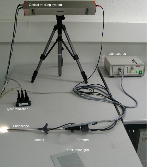
Fig. 30.3
Photograph of the actual system used in the experiments presented in this chapter. The individual components correspond to those illustrated by the sketch in Fig. 30.1
As discussed before, quantitative endoscopy requires pre- or even intraoperative camera calibration to obtain accurate and reliable results. In the following, the term camera calibration is defined as being the procedure to determine the intrinsic parameters of the camera (f c, c c, k c), whereas the computation of the spatial transform between the camera coordinate system and the local coordinate system of the attached fiducial is defined as hand-eye calibration or interior orientation (denoted as H markercam).
Calibrating generic cameras inside the OR is more challenging than under laboratory conditions as the sterilization should not be affected, the required time has to be minimal, and the calibration should be performed by the OR personnel without extensive training. As the camera-endoscope combination is assembled just before the surgery, the calibration has to be performed for each intervention. Depending on the kind of surgery, endoscopes are used either in liquid or in air which has also to be taken into account during calibration, as the intrinsic parameters such as the focal length vary in different media. If an external tracking device is used to report the camera’s position and orientation, a second calibration step for establishing the relationship between the tracker and the camera coordinate system needs to be performed as well, ideally as an integral part of an overall calibration process as proposed in [128].
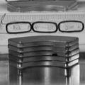
Several aspects of performing camera calibration in the OR are crucial and have been largely ignored in the literature. Preserving the sterility, the ease of use, inhomogeneous illumination conditions, and the generally severe lens distortion need to be investigated carefully and taken properly into consideration to guarantee a successful application in the OR. Instead of the commonly used chessboard, a new pattern consisting of a grid of dots and two special marks for identifying the local coordinate system has therefore been designed for the presented system.
The grid is made of aluminum and the pattern is oxidized onto its surface, thus withstanding any sterilization method. Additionally, a sterilizable mechanical system to position the endoscope rigidly over the calibration plate for tremor-free images (only needed for interlaced cameras) was built. Finally, a box to immerse the calibration grid into liquid was constructed. This is needed for surgeries where distension fluid is used, as the intrinsic camera parameters vary in different mediums.
The procedure for calibrating the camera is straightforward: The surgeon needs to take at least two images of the calibration grid from different viewpoints (although more images are recommended). Except the endoscope’s light source, no additional illumination is required. Once the images are acquired, the calibration is performed in a fully automatic fashion. The images are processed, the points extracted and matched against a virtual representation of the grid points to establish the necessary 2D/3D correspondences, which allow to calibrate the camera.
If an external tracking device is used to report the camera’s position and orientation, the transformation between the world coordinate system of the tracking device and the camera’s internal coordinate system lying on the image plane needs to be computed. In Fig. 30.1, all the coordinate systems implicated in the system are shown in light gray.
In order to find the relationship between the tracked marker and the camera, an extension of the calibration framework presented before is proposed. This allows to establish the missing relationship in a second step based on the camera calibration, in order to find the hand-eye transformation (or interior orientation H markercam).
At least three distinct camera positions, resulting in two linearly independent camera movements, are needed to find the missing transformation H markercam . We have relied on the algorithm presented in [120] was applied to solve for the missing transformation X.
For assessing the quality of the calibration, the reprojection error was used.
As has been shown in [120], the rotational error of the tracker measurements defined by the marker size has a much bigger influence on the reprojection error compared to the translational error.
3D Reconstruction for Registration and Referencing in Spine Surgery
In order to avoid the usage of invasive markers, our system relies on natural landmarks for 3D reconstruction by tracking them over multiple endoscopic views.
The underlying algorithm consecutively refines the 3D model with each additional view. The resulting reconstruction provides quantitative metric data about the target anatomy which can be used for 3D-3D registration of the organ to the preoperative data and for further referencing.
The aim is to create an intraoperative support environment, which relies as much as possible on the tools and instrumentation used anyway during surgery and does not increase the invasiveness of the intervention just for navigation purposes.
The presented method is general and can be used for any rigid anatomical structure with sufficiently textured surfaces. Here, vertebra referencing for the C1/C2 transarticular screw placement or fixation based on the 3D reconstruction of the C2 vertebra during neurosurgery is presented. Even though this is usually performed today using a microscope, the overall procedure is identical with an endoscopic setup.
Since the introduction of C1/C2 transarticular screw fixation in 1979, the technique has been effectively used for various C1/C2 disorders. However, despite fusion rates close to 100 %, many surgeons hesitate to use this technique. The broad acceptance has been prevented by concerns regarding injuring of the vertebral artery or incorrect screw placement. The vertebral artery is usually well protected by the spine being on its anterior side. However, between C1 and C2, it is much more vulnerable. Therefore, unlike fusions on other vertebrae in the thoracic, lumbar, or sacral area, the C1/C2 case is the most dangerous one and is often used as a reference case for studying new techniques. A study about performing the transarticular screw fixation on cases with a high-riding vertebral artery, resulting in an even narrower isthmus, can be found in [89]. In order to reduce the risk for the patient, this surgery is often performed in a navigated fashion, resulting in a procedure which can hardly be called minimally invasive. The head is fixed to the OR table by a stereotactic frame. An exposure covering approximately C0 to C4 is created for visual access as the surgeons usually use a microscope for the preparation of this surgery. The screws are then inserted through percutaneous tubes introduced into the back. In order to navigate, a fiducial is rigidly attached to the C2 vertebra for referencing. The tubes for inserting the screws are then navigated with respect to the C2 vertebra and with the assistance of fluoroscopic images to ensure the right placement of the tubes/screws, see, e.g. [129], for more details.
Related posts:
Stay updated, free articles. Join our Telegram channel

Full access? Get Clinical Tree


