Introduction to Image-guided and Adaptive Radiation Therapy
Martin J. Murphy
Tianfang Li
In this chapter, we introduce the imaging modalities and scenarios that are used in contemporary radiation therapy and summarize the clinical opportunities and challenges that they present. Each of these topics will be examined in detail in the subsequent chapters.
We can identify three stages of the treatment process during which imaging is or can be used: (a) treatment planning, including anatomic motion assessment; (b) patient setup for treatment; and (c) adaptation to interfraction anatomic changes and intrafraction movement. Each of these stages employs different combinations of imaging modalities in different usage scenarios.
TERMINOLOGY, BACKGROUND, AND REQUIREMENTS OF IMAGE-GUIDED RADIATION THERAPY
We can define image-guided radiation therapy (IGRT) as the use of imaging to plan and initiate radiotherapy treatment. We can then define image-guided adaptive radiation therapy (IGART) as the ongoing use of imaging to monitor, update, and adjust the treatment process and dynamic IGART as the use of streams of imaging data to automatically control the dose delivery in near real time.
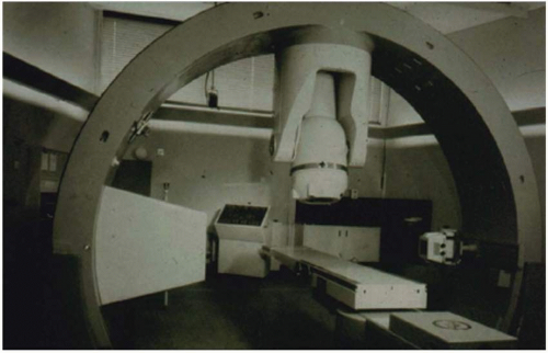
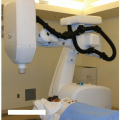
Historically, image guidance in radiotherapy was typically limited to the use of planar and volumetric x-ray images for diagnostic assessment and planning, followed by the use of either megavoltage (MV) portal images or, in some rare instances, kilovoltage (kV) imaging (Fig. 1.1) to align the patient with the treatment machine at the beginning of each fraction.
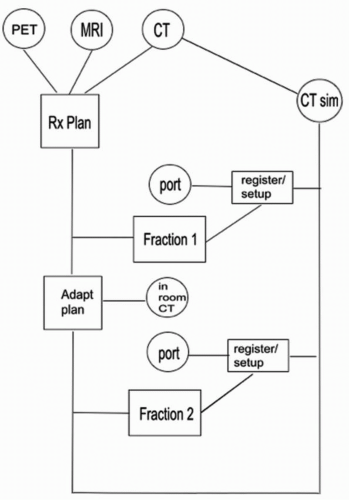
It has since grown to employ multiple imaging modalities for planning, a wide range of image localization devices (using both ionizing and nonionizing radiation) for patient setup, repeated imaging to monitor and adapt to anatomic change, and real-time imaging for motion assessment and tracking. Figure 1.2 schematically illustrates the wide range of imaging modalities and scenarios that can contribute to a single IGART patient treatment. All of the individual imaging modalities have evolved rapidly, as for example in portal imaging, which initially used films, followed by electronic portal imaging devices,1 and now solid-state flat-panel digital imagers.2
Contemporary IGRT employs not only traditional imaging via x-rays and gamma rays (e.g., portal imaging, kV imaging, computed tomography [CT], positron emission tomography [PET], and single-photon emission computed tomography [SPECT]), but also magnetic resonance imaging (MRI), ultrasound (US), and optical cameras, as well as nontraditional imaging based on electromagnetic detection.
IGRT is supported by the processes of image segmentation, registration, and fusion. Image segmentation identifies bounding surfaces for anatomic structures. Image registration finds the geometric transformation that maps the position and shape of anatomic structures from one image to another. Image fusion then uses this mapping to merge multiple sets of diagnostic or dose information into a single image. Both registration and segmentation can be performed manually (i.e., by observers) or automatically.
A complete IGART paradigm must develop each of the following capabilities:
Optimally extract information from the images
Process, analyze, and apply information from the images within the available time for design, guidance, and adaptation of the treatment plan
Use computer-based automatic techniques to achieve the highest possible speed, accuracy, and objectivity in image segmentation and registration
Satisfy clinical expectations of reliability, accuracy, and robustness
Detect faults, errors, and inaccuracies in extracting information from the images and applying it to treatment
Develop methods to fold residual errors and uncertainties associated with each contributing imaging process into the treatment planning and delivery so as to minimize dose margins without underdosing the target
Manage the ionizing radiation dose associated with imaging
IMAGE REGISTRATION FOR IMAGE-GUIDED ADAPTIVE RADIATION THERAPY
By its nature, IGRT involves the use of multiple images acquired from diverse modalities. Image registration is a
mathematical procedure that enables the spatial and temporal association of features in multiple images and the integration of information from them.3, 4, 5, 6, 7 Therefore, it is fundamental to all IGRT operations.
mathematical procedure that enables the spatial and temporal association of features in multiple images and the integration of information from them.3, 4, 5, 6, 7 Therefore, it is fundamental to all IGRT operations.
We can distinguish two broad categories of image registration for two-dimensional (2D) and three-dimensional (3D) images. In rigid registration, all of the anatomy in the image is assumed to be rigidly connected. Under these conditions, one refers to the pose of the patient as the position and orientation of the rigid anatomy within a given imaging coordinate frame. Only six degrees of freedom (three translational and three rotational) are required to uniquely define the patient’s pose. The mapping of anatomic structures from one image to another can then be completely described by the rigid transformation that describes the pose difference between the two images (with perhaps a scale change as well). If individual anatomic elements change their relative position between the two images, then deformable registration is required to define the mapping.8 In deformable registration, there are more than six degrees of freedom.
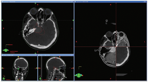
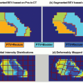
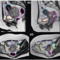
Rigid (or sometimes deformable) image registration is used to relate multiple treatment planning images (such as CT, MRI, and PET) to enable the fusion of information from all images.9 This improves tumor and critical structure delineation, aids detection of involved lymph nodes, and enables biologically guided segmentation and planning. Figures 1.3 and 1.4 illustrate the fusion of PET with CT and MRI with CT.
Rigid registration is also used during patient setup to measure the difference between the patient’s pose in the planning CT and the patient’s pose on the treatment couch. Then either the patient can be moved to reproduce the CT pose or the treatment fields can be adapted to the patient’s observed pose on the couch. Historically, the registration has been done manually by visually aligning 2D simulation and portal images, but it can now be done automatically using 2D/2D, 3D/2D, or 3D/3D rigid registration algorithms.9
If a sequence of planning images has been obtained and the patient’s anatomy has changed shape from one image to the next, then deformable registration can be used to alter segmentation contours on one image to conform to anatomic shapes in the other images, thus speeding up and potentially automating the recontouring process.10,11 This series of images may be obtained prior to the radiation treatment, for example, four-dimensional (4D) PET/CT to study impact of the respiratory motion; or it can be acquired during the treatment course to study the anatomic change and residual errors of delivered dose, which may be used for replanning. Deformable model integrated with image formulation can enhance the quality of the 4D images,12, 13, 14 and deformable registration can be used to map actual delivered doses back to the initial planning CT to obtain accurate cumulative dose records (see, e.g., Schaly et al.15).
TREATMENT PLANNING
Because of the special utility of the CT Hounsfield number in treatment planning, x-ray CT will remain the primary imaging modality for radiotherapy planning for the foreseeable future. It is also the modality best suited for observing high-contrast structures (bones or fiducials) for patient setup and creating appropriate 2D reference (simulation) images for rigid setup registration.
MRI contributes significant anatomic and biologic information to the planning process and thus is frequently used in conjunction with CT. In the same way, PET and SPECT imaging
contribute molecular, anatomic, and metabolic information about the tumor, lymph nodes, and other involved structures. This information is combined in a single anatomic image via the processes of image registration and fusion. Combined PET-CT systems are available to facilitate accurate fusion of molecular imaging data with the planning CT through hardware-based registration. A PET-MRI system is being developed by commercial companies and will soon become available for practical applications.
contribute molecular, anatomic, and metabolic information about the tumor, lymph nodes, and other involved structures. This information is combined in a single anatomic image via the processes of image registration and fusion. Combined PET-CT systems are available to facilitate accurate fusion of molecular imaging data with the planning CT through hardware-based registration. A PET-MRI system is being developed by commercial companies and will soon become available for practical applications.
Cone-beam CT (CBCT) can potentially be used for pretreatment planning. However, it is subject to cupping artifacts and inaccuracies in the Hounsfield number due to its significantly higher scatter-to-primary fluence ratio.16 This can affect the accuracy of the electron densities that are used for dose calculation.17 Charge trapping and incomplete readout in the solid-state imaging panel (image lag) can also make it susceptible to streaking and blurring artifacts that do not arise in fan-beam CT.18 Consequently, at present, the primary use is for in-room setup. However, active research is being carried out in scatter removal,19, 20, 21 dose reduction,22 noise suppression,23 and motion artifacts elimination24,25 to improve the quality of CBCT images.
MVCT has less contrast than kVCT, but it also has less streaking artifact due to high-Z materials. Furthermore, the reconstructed Hounsfield numbers more closely represent the attenuating electron densities seen by the treatment beam, making it potentially useful to the dose calculation component of the treatment planning process.26,27
PRETREATMENT IMAGING FOR MOTION ESTIMATION
Modern techniques to deal with intrafraction organ motion due to respiration are aimed at managing the motion rather than accommodating it via large planning margins. There are three basic approaches to the management problem: (a) reduction of the motion via breath-holding, active breathing control, or assisted ventilation; (b) temporal tracking by detecting the breathing phase and gating the beam on and
off synchronously with the breathing cycle; and (c) spatial tracking by detecting the tumor position and shifting the alignment of the beam synchronously. All three techniques require a pretreatment assessment of the motion to define parameters for its management. Respiration-correlated 4D CT provides one means to analyze the motion over a short time interval (e.g., a few breathing cycles). This procedure involves acquiring an oversampled CT data set that is time stamped so that the data can be sorted into time bins corresponding to discrete moments of the breathing cycle. If the motion is complex, longer periods of observation can be necessary. This can be accomplished with fluoroscopic imaging for periods ranging from 30 seconds to several minutes.28
off synchronously with the breathing cycle; and (c) spatial tracking by detecting the tumor position and shifting the alignment of the beam synchronously. All three techniques require a pretreatment assessment of the motion to define parameters for its management. Respiration-correlated 4D CT provides one means to analyze the motion over a short time interval (e.g., a few breathing cycles). This procedure involves acquiring an oversampled CT data set that is time stamped so that the data can be sorted into time bins corresponding to discrete moments of the breathing cycle. If the motion is complex, longer periods of observation can be necessary. This can be accomplished with fluoroscopic imaging for periods ranging from 30 seconds to several minutes.28
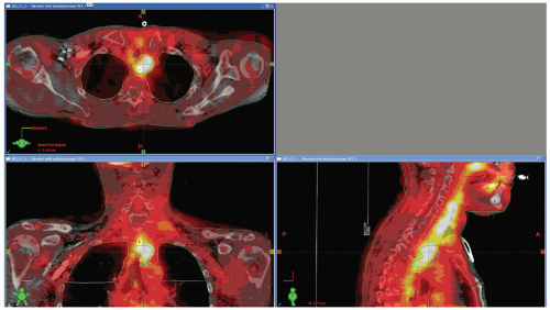 Figure 1.3. Positron emission tomography (PET)/computed tomography (CT) image fusion for a head and neck case. |
SIMULATION AND PRETREATMENT TARGET LOCALIZATION FOR PATIENT POSITIONING
After treatment planning, the most common use of imaging during radiotherapy is patient setup at the beginning of the fraction. This was initially done with MV portal imaging but now can also be done with in-room planar kV imaging, in-room axial CT, in-room CBCT, and nonionizing modalities such as US, optical imaging, and electromagnetic localization.
PORTAL IMAGING
Electronic portal imaging has been established as the gold standard for online verification of patient setup in the past decades. Portal images (projection images using the treatment beam) of the patient from two or more directions are acquired immediately before the radiation delivery and compared to reference (simulation) images portraying the ideal setup position. In sites such as the head and neck, where there is little tumor motion relative to the bony anatomy, bony landmarks can be used for the reference. For other sites, gold markers implanted in or near the tumor may be localized on the portal image and used as the reference.
SIMULATION
Simulation refers to the acquisition of reference setup images to define the treatment position and pose. In-room setup images are compared to the reference images to determine how close the target is to the planned position. Historically, these images were acquired after the CT study in a separate pretreatment procedure using a kV imaging system that mechanically reproduced the patient’s pose in the planning CT while emulating the imaging geometry of the beam port of the treatment machine. The simulation images were then used to define the optimal patient position on the treatment couch. This procedure introduced two sources of positioning error relative to the beams defined in the treatment planning image: (a) a transfer error from CT to simulator due to imperfect replication of the patient’s CT pose in the simulator, and (b) a setup error due to imperfect replication of the simulation pose on the treatment couch. With the advent of fast beam’s eye view digitally reconstructed radiograph (DRR) computation, the simulation images can now be obtained directly from the planning CT (virtual or CT simulation). This eliminates the transfer error from CT to simulator and provides a more precise link between the patient’s pose in the treatment planning CT study and the patient’s pose on the treatment couch.
KILOVOLTAGE PLANAR IMAGING
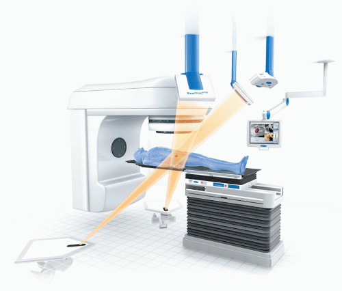
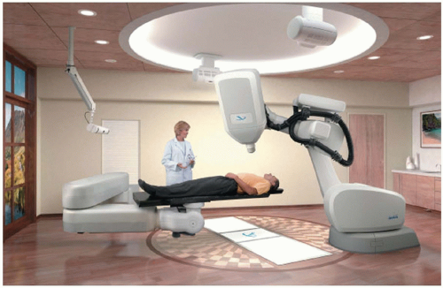
In-room kV imaging replaces MV portal imaging for setup. It almost always involves taking dual orthogonal images at either traditional anteroposterior/lateral viewpoints or oblique angles and registering them to kV virtual DRRs that simulate the imaging geometry. The kV images have better resolution and contrast than MV portal images, thus allowing for more accurate rigid registration to determine the patient’s pose correction, but typically require independent x-ray sources and detectors, thus introducing an element of uncertainty between the imaging and beam isocenters. Examples of currently available fixed in-room kV imaging systems include BrainLAB ExacTrac (BrainLAB, Feldkirchen, Germany; Fig. 1.5) and CyberKnife (Accuray Oncology, Sunnyvale, Calif; Fig. 1.6); examples of gantry-mounted systems include Elekta Planar Imaging (Elekta International, Stockholm, Sweden) and Varian On-Board Imager (Varian Medical Systems, Palo Alto, Calif).
Both portal imaging and in-room planar radiography can accurately locate high-contrast materials such as bone and implanted fiducials but are of limited use in detecting soft tissue position and shape. Combined kV and MV imaging is a clinically useful option when the linear accelerator (linac) is equipped with an onboard kV imaging device.29 This eliminates the need for gantry rotation in obtaining the orthogonal pair of portal images. In-room CT has been developed to assist soft tissue target alignment before the start of treatment.
IN-ROOM COMPUTED TOMOGRAPHY
With the introduction of CT imaging into the treatment room, daily visualization and localization of soft tissue immediately before treatment delivery is now feasible, and initial studies have highlighted the potential for this technology to improve the accuracy of treatment delivery.
Several types of in-room CT imaging systems are now available, including (a) a “CT on rails”30,31 system consisting of a conventional diagnostic CT machine, (b) kV CBCT (kVCBCT) systems32 consisting of an additional kV x-ray source and detector attached to the treatment gantry, (c) tomotherapy systems33,34 replacing the traditional treatment machine (beam) with an MV beam source on a ring gantry equipped with a xenon ion chamber array, and (d) MV CBCT (MVCBCT) systems35 using the pre-existing treatment machine and an electronic portal imaging device.
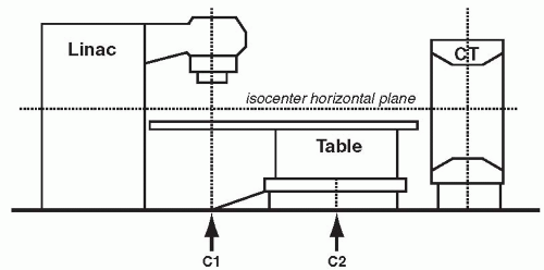
In the CT on rails approach (e.g., Primatom; Siemens Medical Solutions, Concord, Calif), a conventional CT scanner is placed in the treatment room, either on the same couch axis as the linac gantry or on an orthogonal axis to the gantry. A single couch serves the CT scanner and the beam delivery system. The couch is first rotated into alignment with the CT scanner to acquire a pretreatment CT. The CT scanner is mounted on rails so that it, rather than the couch, moves in the axial direction relative to the patient to collect a volumetric scan. This CT is used to establish the time-of-treatment target configuration. The couch is then rotated back into line with the gantry for treatment (Fig. 1.7).
Although the installation of a second costly system in the treatment room can be perceived as somewhat inelegant, it has clear advantages in that it leverages all the development that has been invested in conventional CT technology over the past 20 years, leading to unquestioned image quality and clinical robustness. The geometric accuracy, in combination with excellent image quality, promises excellent management of interfractional setup errors and organ motion. The issue of motion between imaging and delivery remains and will have to be accommodated through the appropriate selection of planning target volume margins.
The shielding requirements for in-room CT systems are far less demanding than those for clinical linacs; the radiation shielding present in existing vaults far exceeds the requirements for kV imaging. However, these systems do impact room design and functionality. For example, in addition to the railing and floor design considerations for a CT on rails system, the cost involved with larger room sizes and associated larger secondary barriers complicates the introduction of such systems into existing radiotherapy rooms. For example, the installation length of the Siemens CT on rails (including the rails and drive motor) is 344 cm. The width of the scanner is 234 cm. The CT gantry can be installed at any angle between 90 and 270 degrees to the linac gantry, and the distance from the isocenter to the backside of the motor drive, installed behind the scanner, is 470 cm. The system has its own power cabinet that is connected to an external power line through a 480-V three-phase isolation transformer.
Helical tomotherapy (HT) is a novel radiotherapy concept that combines elements from a helical CT scanner with an MV linac.33 MVCT in HT34 allows daily patient setup verification and repositioning. It is already possible to image a patient followed by immediate treatment planning and dose delivery in circumstances where targets are small, motionless, and regularly shaped (e.g., intracranial radiosurgery) or where beam arrangements are very simple (e.g., urgent palliative radiotherapy). Eventually, however, with improvements in real-time image collection during dose delivery, this approach could be practical and appropriate for more sophisticated patient treatments in curable patients.
Performance characteristics of MVCT on a tomotherapy system were reported by Meeks et al.36 They studied image noise and uniformity, spatial resolution, contrast properties, and multiple scan average dose with a Cardinal Health AAPM CT Performance Phantom (Cardinal Health, Hicksville, NY). An experimental study comparing MVCT with conventional diagnostic CT scans in dogs with spontaneous tumors concluded that the MVCT image quality is sufficiently good to allow 3D setup verification.37
MVCT provides less soft tissue contrast due to the lower attenuation coefficients at high x-ray energy but, for the same reason, suffers less from beam hardening and the artifacts induced by highly attenuating high-Z materials.
CBCT is a new technology that permits the acquisition of 3D volumetric images using the linac gantry while the patient is in the actual treatment position. Unlike conventional CT scanners, CBCT reconstructs an entire image volume from a single gantry rotation. The resulting image is of high spatial resolution (0.5 mm) in all three dimensions and can have a field of view (FOV) of up to 48 cm in axial diameter and 26 cm in the superior/inferior (SI) extent (Elekta Synergy, Elekta International, Stockholm, Sweden; Varian Trilogy, Varian Medical Systems, Palo Alto, Calif).
There are two basic methods for integration of CBCT imaging within a radiotherapy environment. One approach uses the MV treatment beam of the linac in combination with an electronic portal imaging device (EPID), whereas the other uses an auxiliary kV source such as an x-ray tube in combination with an additional digital x-ray detector. Using the treatment beam for imaging is appealing because this application requires no additional hardware (along with the associated expense and maintenance), and the image is obtained in exact geometric coincidence with the treatment, but MVCT has deficiencies in sensitivity and contrast compared to kVCT.
Although MVCBCT may provide a valuable means of correcting 3D setup errors and may offer an advantage in terms of simplicity of mechanical integration with a linac (e.g., implementation in place of a portal imager), kVCBCT offers significant performance advantages in terms of image contrast and signal-to-noise ratio (SNR) per unit dose for visualization of soft tissue structures.38 The origins of image contrast are different for kV and MV imaging (photoelectric effect vs. Compton effect). The relatively poor SNR performance at MV energies is primarily a result of the low x-ray quantum efficiencies (approximately a few percent or less) that are currently achieved with flat-panel imagers (FPIs) at high energies. Furthermore, kVCBCT with an FPI offers the potential of combined volumetric and radiographic/fluoroscopic imaging using the same device.
