14 The figures given are for 1.5 T and 3 T systems. Parameters are dependent on field strength and may need adjustment for very low or very high field systems. Figure 14.1 Anterior view of the right hip demonstrating bony components and ligaments. Note: Bilateral and unilateral examinations of the hips are described in this section. The causes of generalized hip pain include AVN, metastatic deposits and occult fractures, which may affect both hips. Specific unilateral joint pathologies such as suspected labral tears or chondral damage require high-resolution imaging of the hip in question. However, due to the prevalence of AVN in patients presenting with hip pain, it is advisable to include a bilateral sequence in unilateral hip protocols. The patient lies supine on the examination couch with their legs straight and both feet parallel to each other. This ensures that the angle of both femoral necks is the same, although they do not necessarily have to be internally rotated as in radiography of the hips. The legs are immobilized with the use of pads and straps wrapped around both feet. This enables the patient to maintain the position in a relaxed fashion. The patient is positioned so that the longitudinal alignment light lies in the midline, and the horizontal alignment light passes through the level of the femoral heads. They are localized by palpating the femoral pulse, which is typically found 3 cm inferiorly and laterally to the midpoint of the line joining the anterior superior iliac spine (ASIS) and the pubic symphysis. If only one hip is imaged, the FOV will be offset from isocentre and image quality may be affected. Acts as a localizer if three-plane localization is unavailable, or as a diagnostic sequence. Thick slices/gaps are prescribed on either side of the horizontal alignment light. Both hips are included to show the location and alignment of the hips. Axial I 25 mm to S 25 mm Thin slices/gaps are prescribed from the posterior to the anterior margins of the musculature of the hip (from the iliacus to the anterior portion of gluteus maximus). Slices may be angled to compensate for positional rotation of the pelvis. The images should display the lateral edges of the muscles surrounding the hips (gluteus medius), and extend from the junction of the ilium and the superior acetabulum to below the lesser trochanter. Figure 14.2 Coronal FSE T1 image of both hips and femora. Slice prescription as for coronal T2. Thin slices/gap are prescribed from above the articular portion of the acetabulum to the superior edge of the lesser trochanter, and aligned with the superior surface of both femoral heads to correct for positional errors (Figure 14.3). Figure 14.3 Coronal FSE T1-weighted image showing slice prescription boundaries and orientation for axial imaging of the hips. Thin slices/gaps are prescribed from the lateral aspect of the greater trochanter through the articular portions of the acetabulum (Figure 14.4). These images particularly demonstrate flattening of the femoral head associated with AVN. Generally, FSE is the sequence of choice, but GRE sequences provide excellent visualization of cartilage. Figure 14.4 Coronal FSE T1-weighted image showing slice prescription boundaries and orientation for sagittal imaging of the hips. This examination usually demands higher resolution than bilateral exams. Image planes should be placed relative to the anatomy of the joint rather than orthogonal to the body. Extra shimming may be required to optimize tissue suppression performance and GRE image quality in an offset FOV. Acts as a localizer if three-plane localization is unavailable, or as a diagnostic sequence. As for bilateral examination. Use the body coil and include both hips. Thin slices/gap are prescribed from the posterior to the anterior margins of the femoral head and aligned parallel to the femoral neck. The area from the proximal margin of the femoral shaft (below the lesser trochanter) to the greater sciatic notch is included in the image. Slice prescription as for the coronal T1. T2* images are particularly good for identifying the labrum and loose bodies in the joint. A FSE T2 may be preferred to provide higher resolution. Thin slices/gaps are prescribed from a coronal image to include the articular components of the hip joint. Angle the slices so that they are parallel to the femoral neck. Slice prescription as for axial T2. This may be used as an additional sequence to the unilateral examination, especially to rule out AVN of the asymptomatic hip. Use the body coil to avoid repositioning of the patient. Medium slice/gap is adequate as the contrast sensitivity of the sequence should identify pathology. Position slices to include the bony components of the hip joint and some surrounding musculature. This sequence, with thin slices/gap and fine matrices, may be used to visualize the labral tears. Figure 14.5 Coronal arthrogram. Figure 14.6 Axial arthrogram. This sequence may be used after intra-articular injection of contrast to visualize labral tears and chondral defects. A very dilute solution of gadolinium contrast agent in saline (1:100) is introduced into the joint capsule, and the single joint is imaged at high resolution with tissue suppression. T1-weighted images in three planes are acquired aligned to the femoral neck and acetabular rim. The TE influences the signal of the muscle in musculoskeletal imaging. A very long TE produces T2-weighted images in which muscle is hypo-intense. The SNR is therefore reduced but fluid detection is improved. Tissue suppression can also be used to enhance the signal from fluid even further; however, larger voxels may be required to compensate for the inherent drop in SNR. By choosing a moderate TE, muscle still retains signal (a grey-level intensity) and the images are PD weighted. The SNR is however higher and the spatial resolution can be better than a T2-weighted image. This kind of contrast is used to detect fluid and retain an anatomical image. Tissue suppression techniques are recommended with this kind of weighting because signal from fluid is reduced. Cartilage lesions can be better detected when TE is high (at least 30–40 ms) because the signal from normal cartilage decreases. Spatial resolution is a critical parameter in joint imaging and depends on the clinical indications. For example, when examining small labral tears, resolution is paramount and utilization of thin slices/gap and a fine high matrix is necessary. However, when the lesion is large and CNR is high, resolution can be sacrificed to achieve better SNR or shorter scan times. Volume acquisitions are sometimes valuable as very thin slices with no gap are used, and joint structures may be visualized in any plane. As volume acquisitions are usually performed in order to demonstrate anatomy, an incoherent (spoiled) GRE sequence that produces predominantly T1 weighting is required. Bilateral and unilateral examinations have been described in this section. Bilateral imaging with a large phased array coil has a number of advantages. It can provide acceptable resolution for visualizing joint structures when used with a combination of a small FOV and oversampling, but it can also be utilized with a large FOV to provide medium-resolution images of a large area of anatomy. For unilateral examinations, the requirement for fine spatial resolution is paramount. The hip joint structures are comparable in size to the shoulder, requiring high spatial resolution (pixel size less than 0.5 mm). Unfortunately, the relatively bulky musculature and the external morphology of the hip demands physically larger coils. As a result, it may be necessary to use higher NEX/NSA and longer scan times to achieve acceptable SNR. Flexible selection of a rectangular/asymmetric FOV has greatly helped to tailor hip sequences in the axial and sagittal planes. In addition, flexible application of oversampling allows a small FOV to be used in the coronal and axial planes in conjunction with larger coils, as well as providing finer incremental changes in SNR. Several sequences are employed in hip examinations. SE sequences usually provide better contrast and resolution in T1-weighted images than FSE. However, the development of high-performance gradients reduces blurring associated with long ETLs. Tissue suppression is an important imaging option in the musculoskeletal system, as the suppression of normal fatty marrow often enhances the visualization of bony pathology. Tissue suppression techniques are usually preferred, but STIR sequences provide very uniform fat suppression (and the degree of the fat suppression can be controlled by altering the inversion time), particularly on older systems and in large FOVs. There is a developing trend to use moderately short TE acquisitions (35–60 ms) for fat-suppressed PD-weighted FSE sequences which yield higher SNR and improve CNR between cartilage and muscle. The efficacy of this approach has not yet been established. Additional shimming may be required before tissue suppression sequences. While reduced bandwidth sequences offer SNR increases without serious time penalties, the bandwidth should be chosen to limit the chemical shift to one or two pixels for most non-fat-suppressed sequences and particularly when producing high-resolution images. When a tissue suppression technique is used, chemical shift artefact is less problematic and a lower bandwidth can be used. However, because a reduced bandwidth improves SNR, flow sensitivity and therefore flow artefacts are more evident. The main source of artefact is from flow within the femoral and iliac vessels. Spatial pre-saturation pulses placed S and I to the FOV reduce this to a large degree. When imaging a single hip for labral tears, bowel motion may be troublesome. Placing a spatial pre-saturation pulse medial to the hip effectively reduces this. GMN further minimizes flow artefact, but as it increases the signal in vessels and the minimum TE, it is not usually beneficial in T1-weighted sequences. However, GMN can effectively increase contrast (depending on the direction GMN is applied) in synovial fluid in T2- and T2*-weighted images. For FSE imaging, using a high receive bandwidth and/or shorter ETL reduces flow artefact and motion reduction techniques, such as PROPELLER, are also beneficial. For bilateral coronal acquisitions, fat suppression may not be homogenous due to the use of a large FOV. Therefore, additional shimming may be required before tissue suppression sequences. Alternatively, STIR sequences may be used. Techniques that use the 3-point Dixon method whereby four images are acquired in one sequence (water, fat, in and out of phase), provide robust fat-suppressed images (fat–water separation). Hip prosthesis or pins produce significant magnetic susceptibility artefact. This can sometimes, but not always, ruin an image. Do not use a GRE sequence as gradients do not compensate for magnetic field inhomogeneities, thereby increasing magnetic susceptibility artefact. To minimize the artefact, select SE or FSE sequences in conjunction with a broad receive bandwidth, a lower TE and a coarser matrix. The artefact can sometimes be shifted away from the ROI by swapping the phase and frequency encoding directions, but this, in turn, may lead to aliasing. However, aliasing can be avoided by oversampling and careful location of the hands away from the side of the body and on to the chest. Chemical suppression techniques cannot be used when metallic implants are present. Other types of suppression or STIR sequences are recommended. Recently, protocols have been developed for imaging soft tissue in the vicinity of metallic prosthesis. These techniques significantly reduce magnetic susceptibility artefact, and therefore, inflammation can be detected close to the prosthesis. Patients with a hip prosthesis may experience warmth during the examination. They have to be warned of this, and an emergency bell has to be provided and used in case of any discomfort. Due to excessively loud gradient noise associated with some sequences, earplugs/headphones must always be provided to prevent hearing impairment. IV contrast is virtually never indicated in hip joint imaging unless as an indirect MR arthrography technique (see Shoulder in Upper Limb). Direct MR arthrography of the hip is an important technique in the diagnosis of some hip disorders, especially labral tears. Arthrography techniques include: Figure 14.7 Anterior view of the right femur. A bilateral examination is recommended for all new cases, but single-sided imaging can be used for follow-up examinations, particularly if an array coil is unavailable. The patient lies supine on the examination couch with their legs straight and their feet in a comfortable position. The feet are immobilized in this position using pads and straps. The patient is positioned so that the longitudinal alignment light lies in the midline, and the horizontal alignment light passes through a point midway between the knee and the hip (or over the ROI if this is known). If only one side is to be imaged, the patient should be moved until the femur is as close as possible to the midline of the bore. Use the plastic ruler to measure from the horizontal alignment light to each joint to ensure the full femur fits within the long axis of the FOV. If not, include either the knee or hip depending on the location of the lesion(s). When a lesion is palpable, place an oil- or water-filled marker over it for easy localization. For large lumps or scars, place a marker at each end. Acts as a localizer if three-plane localization is unavailable, or as a diagnostic sequence. Axial localizers are useful to locate lesions in the SI axis but do not indicate if the full length of the femur will be included in the other planes. Coronal localizers locate lesions situated in the RL axis. Medium slices/gap are prescribed from skin surface to skin surface. In the coronal plane, the entire length of the femur should be included in the image. Axial localizer: I 100 mm to S 100 mm Coronal localizer: P 50 mm to A 40 mm Medium slices/gap are prescribed to include the entire thigh and aligned parallel to the long axis of the femur. If bilateral lesions are suspected, repeat this sequence on the other leg. Medium slices/gap are prescribed to include the entire thigh from the anterior to the posterior skin surfaces and aligned parallel to the long axis of the femur. This sequence enables visualization of both femora for comparison and identification of lesions in the marrow space. Slice prescription as for coronal SE/FSE T1 Medium slices/gap are prescribed to extend from well below to well above lesions seen on the coronal or sagittal images. Axial images are useful for localizing lesions within significant anatomical compartments. Breach of the marrow space, extension within or through muscle compartments and association with the neurovascular bundle are all significant characteristics. Slice prescription as for the axial T1. The inherent contrast is relatively good in this area due to the apposition of muscle and fat. The TE influences the signal of the muscle in musculoskeletal imaging. A very long TE produces T2-weighted images in which muscle is hypo-intense. The SNR is therefore reduced but fluid detection is improved. Tissue suppression can also be used to enhance the signal from fluid even further; however, larger voxels may be required to compensate for the inherent drop in SNR. By choosing a moderate TE, muscle still retains signal (a grey-level intensity) and the images are PD weighted. The SNR is however higher and the spatial resolution can be better than a T2-weighted image. This kind of contrast is used to detect fluid and retain an anatomical image. Tissue suppression techniques are recommended with this kind of weighting because signal from fluid is reduced. Cartilage lesions can be better detected when TE is high (at least 30–40 ms) because the signal from normal cartilage decreases. The use of sensitive coils and medium-resolution imaging permits relatively fast examinations in the sagittal and coronal planes. As a result, more time can be spent acquiring higher-resolution axial images when necessary. Lesions close to the neurovascular bundle or subtle cortical bone breaches are examples of when this strategy might be utilized. A surface coil increases the signal substantially as compared with the body coil, but signal fall-off in the anterior part of the thigh often prohibits its use. The body array coil must be positioned to provide coverage of the entire thigh. Total coverage of both femora is necessary in the evaluation of bony tumours to ensure that additional skip lesions are detected. Good spatial resolution is usually achievable especially if FSE is used, as fine matrices can be selected without unduly lengthening the scan time. A rectangular/asymmetric FOV can be implemented in the sagittal and axial planes with the long axis of the rectangle either R to L or S to I, respectively. Tissue suppression techniques are commonly utilized, especially in FSE T2-weighted images, where the signal from fat remains bright and may return a similar signal to pathology. Additional shimming may be required before tissue suppression sequences. In T2 FSE, the signal returned from muscle is usually lower than in SE, thereby increasing conspicuity of some lesions. To enable accurate characterization of a new lesion, MRI must be performed before tissue biopsy or partial excision. Chemical shift artefact must be kept within one pixel, particularly in axial images, to delineate the interface of marrow and cortical bone and the edges of muscle compartments clearly. Flow artefact from the femoral vessels is the main source of phase ghosting in this area. Spatial pre-saturation pulses placed S and I to the FOV reduce this effectively. GMN minimizes the artefact, but as it increases the minimum TE, it is not usually beneficial in T1-weighted sequences. Patients with a hip prosthesis may experience warmth during an examination of the femur especially if there is a long femoral component. Warn them that this may occur and provide them with an emergency bell in case any discomfort is noticed. Due to excessively loud gradient noise associated with some sequences, earplugs or headphones must always be provided to prevent hearing impairment. Contrast is not routinely used in the femur. It may, however, be useful for tissue characterization of certain tumours.
Lower limb
1.5 T
3 T
SE
SE
Short TE
Min–30 ms
Short TE
Min–15 ms
Long TE
70 ms+
Long TE
70 ms+
Short TR
600–800 ms
Short TR
600–900 ms
Long TR
2000 ms+
Long TR
2000 ms+
FSE
FSE
Short TE
Min–20 ms
Short TE
Min–15 ms
Long TE
90 ms+
Long TE
90 ms+
Short TR
400–600 ms
Short TR
600–900 ms
Long TR
4000 ms+
Long TR
4000 ms+
Short TEL
2–6
Short TEL
2–6
Long ETL
16+
Long ETL
16+
IR T1
IR T1
Short TE
Min–20 ms
Short TE
Min–20 ms
Long TR
3000 ms+
Long TR
300 ms+
TI
200–600 ms
TI
Short or null time of tissue
Short ETL
2–6
Short ETL
2–6
STIR
STIR
Long TE
60 ms+
Long TE
60 ms+
Long TR
3000 ms+
Long TR
3000 ms+
Short TI
100–175 ms
Short TI
210 ms
Long ETL
16+
Long ETL
16+
FLAIR
FLAIR
Long TE
80 ms+
Long TE
80 ms+
Long TR
9000 ms+
Long TR
9000 ms + (TR at least 4 × TI)
Long TI
1700–2500 ms (depending on TR)
Long TI
1700–2500 ms (depending on TR)
Long ETL
16+
Long ETL
16+
Coherent GRE
Coherent GRE
Long TE
15 ms+
Long TE
15 ms+
Short TR
<50 ms
Short TR
<50 ms
Flip angle
20–50°
Flip angle
20–50°
Incoherent GRE
Incoherent GRE
Short TE
Minimum
Short TE
Minimum
Short TR
<50 ms
Short TR
<50 ms
Flip angle
20–50°
Flip angle
20–50°
Balanced GRE
Balanced GRE
TE
Minimum
TE
Minimum
TR
Minimum
TR
Minimum
Flip angle
>40°
Flip angle
>40°
SSFP
SSFP
TE
10–15 ms
TE
10–15 ms
TR
<50 ms
TR
<50 ms
Flip angle
20–40°
Flip angle
20–40°
Slice thickness 2D
Slice thickness 3D
Thin
2–4 mm
Thin
<1 mm
Medium
5–6 mm
Thick
>3 mm
Thick
8 mm
FOV
Matrix
Small
<18 cm
Coarse
256 × 128/256 × 192
Medium
18–30 cm
Medium
256 × 256/512 × 256
Large
>30 cm
Fine
512 × 512
Very fine
>1024 × 1024
NEX/NSA
Slice number 3D
Short
1
Small
<32
Medium
2–3
Medium
64
Multiple
>4
Large
>128
PC-MRA 2D and 3D
TOF-MRA 2D
TE
Minimum
TE
Minimum
TR
25–33 ms
TR
28–45 ms
Flip angle
30°
Flip angle
40–60°
VENC venous
20–40 cm/s
VENC arterial
60 cm/s
TOF-MRA 3D
TE
Minimum
TR
25–50 ms
Flip angle
20–30°
Hips
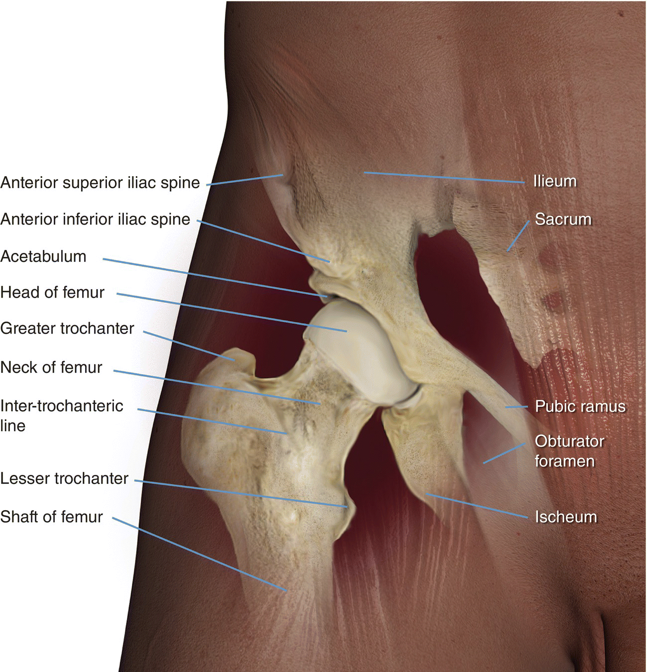
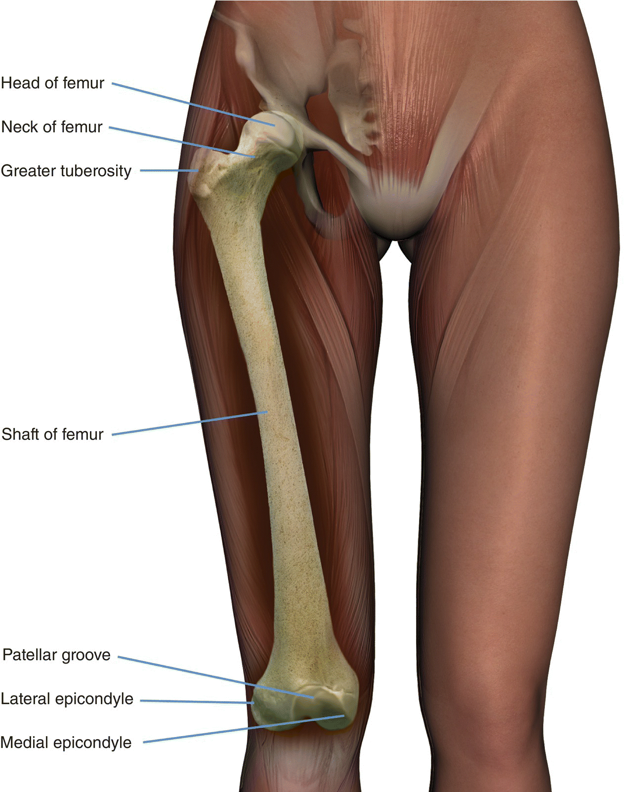
Basic anatomy (Figure 14.1)
Common indications
Equipment
Bilateral hip imaging
Single hip imaging
Patient positioning
Suggested protocol: bilateral examination
Axial SE/FSE/incoherent (spoiled) GRE T1
Coronal FSE T2 +/– tissue suppression/STIR
Coronal SE/FSE T1 (Figure 14.2)
Axial SE/FSE T1
Sagittal FSE T2/coherent GRE T2* +/– tissue suppression
Suggested protocol: unilateral examination
Axial SE/FSE/incoherent (spoiled) GRE T1
Coronal SE/FSE T1
Coronal coherent GRE T2*/FSE T2 +/– tissue suppression
Axial FSE T2 +/− tissue suppression
Axial SE/FSE/incoherent (spoiled) GRE T1
Additional sequences
Coronal FSE T2 +/– tissue suppression (both hips)
Coronal/oblique FSE T2 + tissue suppression (both hips)
SE/FSE/incoherent (spoiled) GRE T1 + contrast (Figures 14.5 and 14.6)
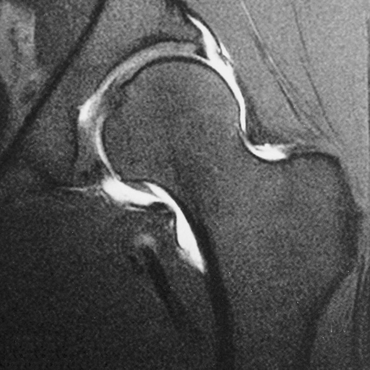
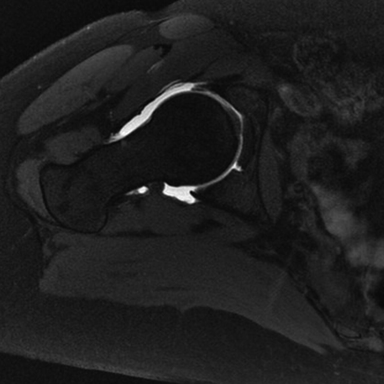
Image optimization
Technical issues
Artefact problems
Patient considerations
Contrast usage
Femur
Basic anatomy (Figure 14.7)
Common indications
Equipment
Patient positioning
Suggested protocol
Axial/coronal/multi-planar SE/FSE T1/T2 or SS-FSE or incoherent (spoiled) GRE T1
Sagittal STIR
Coronal SE/FSE T1
Coronal/oblique SE/FSE T2 + tissue suppression bilateral or coronal STIR bilateral
Axial SE/FSE T1
Axial SE/FSE T2 +/− tissue suppression
Image optimization
Technical issues
Artefact problems
Patient considerations
Contrast usage
Knee
Basic anatomy (Figure 14.8)
Related posts:
![]()
Stay updated, free articles. Join our Telegram channel


Full access? Get Clinical Tree


