Mitral Valve Repair
INDICATIONS
Mitral valve (MV) regurgitation is the most prevalent isolated heart valve disease (1), and valve repair or replacement remains the only effective treatment for chronic severe disease (2,3).
MV regurgitation results from either structural or functional disorder (2,3). Structural (or primary) MV regurgitation is most commonly caused by degenerative MV disease and implies pathology of the architecture of the MV apparatus, that is, the valve leaflets, chordae tendineae, or papillary muscles. Functional (or secondary) MV regurgitation implies that the mitral apparatus itself is structurally normal, and regurgitation is then typically caused by ischemic or dilated cardiomyopathy. In these cases of functional mitral disease, regurgitation results from displacement of the papillary muscles consequent to left ventricular (LV) dilatation often in combination with mitral annular dilatation. The displacement of the papillary muscles causes tethering of the valve leaflets and restricts their motion, thereby preventing coaptation (4).
MV repair improves long-term survival if patients are operated on early and in centers which have both low operative mortality (<1%) and high rates of repair (80% to 90%), as opposed to valve replacement (5,6). Patients who undergo MV repair rather than valve replacement clearly demonstrate lower operative mortality, better recovery of left ventricular ejection fraction (LVEF), and better long-term survival (7,8). This improvement in outcome for patients treated with repair versus replacement is intuitive considering that they have lower rates of endocarditis, fewer thromboembolic events, and do not require long-term anticoagulation (unless otherwise indicated).
Chronic severe mitral regurgitation (MR) ultimately leads to LV dilatation. To maintain forward stroke volume in the face of significant regurgitant fraction, the LV chamber necessarily becomes more compliant and develops eccentric cardiac hypertrophy. Pulmonary congestion then decreases also, as the now dilated left atrium and ventricle can accommodate the regurgitant volume at lower filling pressure. These early responses are therefore adaptive and during this phase the patient may remain asymptomatic. Over time, however, the progressive LV enlargement and increasing LV end-diastolic pressures lead to a reduction in LVEF. With progressive left atrial dilatation, the onset of atrial fibrillation and/or pulmonary hypertension can develop, and their occurrence in patients with chronic severe MR constitutes an indication for surgery, even in patients with preserved LVEF and LV end-systolic diameter less than 40 mm (2,3).
The recommendations for the timing of surgery in patients with chronic severe MR rely on patient symptoms and also on echocardiographic evaluation of LV function and size (Fig. 10.1) (2,3). It is noteworthy that patients with chronic severe MR, who are symptom free, have normal LV dimensions and function, and do not have atrial fibrillation or pulmonary hypertension, are only recommended to undergo valve surgery if it is likely that the valve can be repaired rather than replaced. The current recommendations also suggest medical therapy for symptomatic patients who have depressed LV function and/or LV dilatation, in whom chordal preservation is unlikely with conventional surgery; the option of percutaneous repair is not yet considered in these guidelines. Although the percutaneous mitral clip procedure is less effective in reducing MR than conventional repair surgery, it is associated with fewer major adverse events than conventional repair and does improve patients’ clinical condition (9). Long-term results are not yet available for the percutaneous mitral clip procedure but it may prove to be a valid alternative to medical therapy for this cohort.
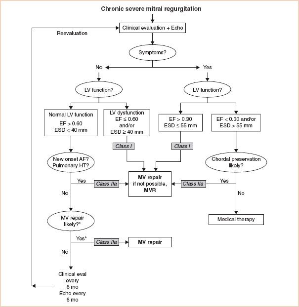
FIGURE 10.1 Guidelines for the management of patients with chronic severe mitral regurgitation. *Mitral valve (MV) repair may be performed in asymptomatic patients with normal left ventricular (LV) function if performed by an experienced surgical team and if the likelihood of successful repair is greater than 90%. AF indicates atrial fibrillation; echo, echocardiography; EF, ejection fraction; ESD, end-systolic dimension; eval, evaluation; HT, hypertension; and MVR, mitral valve replacement. Adapted from: Circulation. 2008;118:e523–e661.
ECHOCARDIOGRAPHIC EVALUATION
Intraoperative transesophageal echocardiography (TEE) is a class I indication for patients undergoing MV repair (10), meaning that its use improves patient outcome. The role of intraoperative echocardiography can be considered as two components: Pre- and postrepair.
THE PREREPAIR EVALUATION
The prerepair examination should evaluate the following:
1. Structure of the MV apparatus
2. Function of the MV leaflets according to the Carpentier classification
3. Severity of the MV regurgitation
4. Circumflex artery and its relationship to the MV annulus
5. Cardiac structures for secondary or coexisting abnormalities
This information is then summarized and the likelihood of successful repair discussed with the surgical team so to be of use in planning the surgical procedure.
1. Evaluation of the Structure of the Mitral Valve Apparatus
The MV apparatus consists of the MV annulus, the MV leaflets (anterior and posterior), chordae tendineae, papillary muscles, and left ventricle. The nomenclature proposed by Carpentier to describe the segments of the mitral leaflets (11) is the most commonly used and is widely accepted as standard (Fig. 10.2). The anatomy of the mitral apparatus is detailed in Chapter 8, Mitral Regurgitation. To visualize all the structures of the MV apparatus and to elucidate fully the mechanism of MR and any associated pathology, several views are necessary (12).
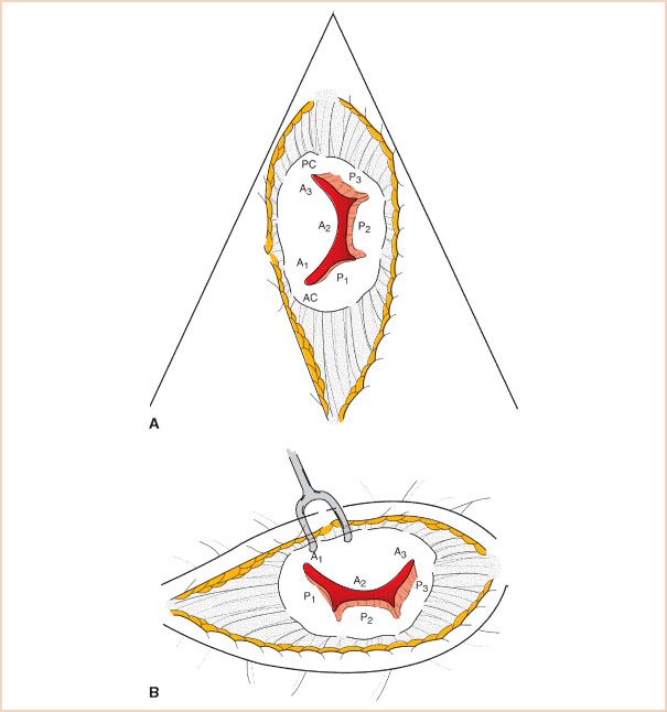
FIGURE 10.2 Mitral valve leaflet segments using the Carpentier leaflet nomenclature. A: Echocardiographic short-axis or “fish mouth” view. B: Surgeon’s view through open left atrium from the patient’s right side. The echocardiographic view is rotated 90 degrees counterclockwise relative to the surgeon (tilting one’s head to the left).
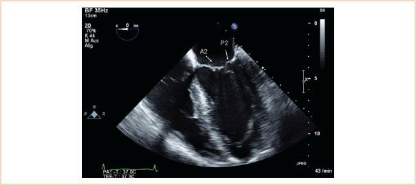
FIGURE 10.3 ME four-chamber view, with in this case A2 and P2 segments labeled. Although the typical ME four chamber most often cuts through these segments, it is possible to view A1, P1 by slight probe withdrawal, or A3, P3 by slight probe advancement (see Fig. 10.4).
Midesophageal (ME) four-chamber view: Normally shows the A2 and P2 segments of the MV (Fig. 10.3). From there, slight withdrawal of the probe will show the A1 and P1 segments, whereas slight advancement of the probe will show the A3 and P3 segments (Fig. 10.4). LV systolic function can also be assessed in this view by measuring LVEF. Interpretation of LVEF must take account of the patient’s loading conditions, and patients with MR who have normal LV function demonstrate LVEF greater than or equal to 60% (3). Patients with reduced LVEF preoperatively also have reduced postoperative LVEF, higher perioperative mortality, and poorer long-term survival (13,14).
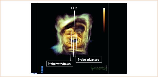
FIGURE 10.4 Three-dimensional full volume en face view of the mitral valve from the left atrium, with the aortic valve located at approximately 12 o’clock. The middle line (4 Ch) shows how the typical ME four-chamber view cuts through A2, P2 segments. Probe withdrawal means the 2D probe now would cut through A1, P1, and in the corresponding 2D view, more of the aortic valve/LVOT enters the image. Probe advancement moves the 2D scan plane over A3, P3 segments.
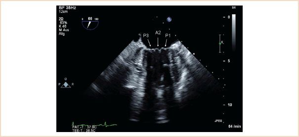
FIGURE 10.5 ME commissural view which typically shows the P3, A2, P1 segments.
ME mitral commissural view: From the ME four-chamber view, the MV should also be scanned by forward rotation to show the P3, A2, and P1 segments (Fig. 10.5). Continued forward rotation produces the ME two-chamber view with P3, A3, A2, and A1 segments (Fig. 10.6) and ME LAX views with the P2 and A2 segments (Fig. 10.7).
From the ME position, the probe is advanced into the stomach to obtain the transgastric (TG) views.
TG mid-SAX view: Regional wall motion abnormalities as well as global LV function can be assessed by measuring fractional shortening or fractional area change. This view serves as the reference view for possible new regional wall motion abnormalities which may arise due to complications of the MV repair in the postrepair examination (see postrepair examination).
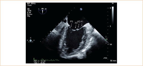
FIGURE 10.6 ME two-chamber view. Forward rotation from the ME commissural view to approximately 90 to 100 degrees reveals P3, A3, A2, A1 segments.
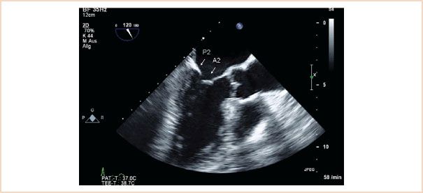
FIGURE 10.7 ME LAX view. The left atrium, left ventricle, left ventricular outflow tract, and aortic valve are viewed. When there is no foreshortening, the mitral valve segments viewed are A2, P2.
TG two-chamber view: The ultrasound beam travels perpendicular to both the papillary muscles and chordae so that these two structures are often very clearly visualized (Fig. 10.8). LV diameters are measured in this view (15).
TG basal SAX view: Shows all segments of the MV leaflets together with both commissures (Fig. 10.9). This view allows for planimetric measurement of the MV orifice area. An existing cleft pathology in one of the leaflets can often be diagnosed in this view during diastole (Video 10.1, cleft anterior mitral leaflet). The use of color flow Doppler (CFD) helps to confirm the diagnosis (Video 10.2, CFD cleft anterior mitral leaflet), and with real-time (RT) 3D TEE the cleft can often be better elucidated (Video 10.3, cleft posterior mitral leaflet).
Three-dimensional assessment of the MV: The additional value of RT 3D TEE for the evaluation of MV pathology is still a matter of debate (16,17). There is a high level of consistency between RT 3D TEE assessment of MV pathology and the findings of macroscopic surgical inspection (18). The most important potential advantages of RT 3D TEE are that it is capable of providing several unique views and images which are intuitively more understandable. RT 3D TEE is probably the method of choice when available as it can complement the standard 2D examination (19).
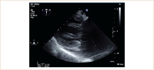
FIGURE 10.8 TG two-chamber view. This view is particularly helpful in demonstrating structural pathology of the subvalvular apparatus, as the beam travels perpendicular to these structures, enhancing their visualization.
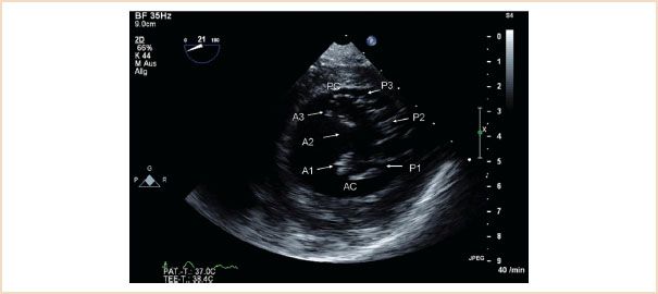
FIGURE 10.9 TG basal SAX. This view can be difficult to optimize, in its true form it reveals the basal left ventricle in short axis, allowing basal wall motion abnormalities to be identified. In this figure the posteromedial commissure (PC) and anterolateral commissure (AC) are visible. All six segments of the mitral valve are also identified. Mitral valve opening area can be measured by planimetry. Applying CFD can often help to localize regurgitant jets.
The guidelines for image acquisition and display using 3D echocardiography (20) recommend that the MV be displayed with the aortic valve placed superiorly, regardless if the MV is oriented as viewed from the left atrium or left ventricle. This brings the advantage that the anterior leaflet is readily identifiable inferior to the aortic valve; the posterior leaflet must then be further inferior in this view. Viewed from the atrial side, then the valve segments are named 1, 2, and 3, from left to right (Fig. 10.10). The view from the left atrium is the most intuitively understandable and helpful 3D view of the MV (also referred to as the “en face” or “surgical” view). This view is often particularly helpful in translating the TEE findings to the surgeon, as in this single view all segments of the MV can be seen and pathology can often be clearly localized, especially in cases of excessive leaflet motion (Fig. 10.11, Video 10. 4). Cleft defects, indentations, or leaflet perforations are often distinctly better viewed in this view compared to standard 2D images.
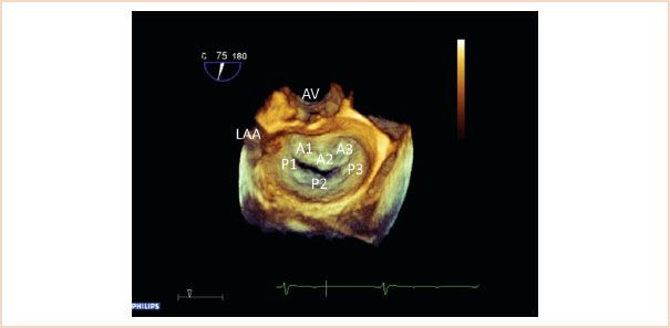
FIGURE 10.10 Three-dimensional view of the mitral valve from the left atrial perspective. The aortic valve (AV) is positioned superiorly, the left atrial appendage (LAA) is also visible. This view is also referred to as the “en face view” or “surgeon’s view” of the mitral valve. All leaflet segments are simultaneously visible and are labeled here.
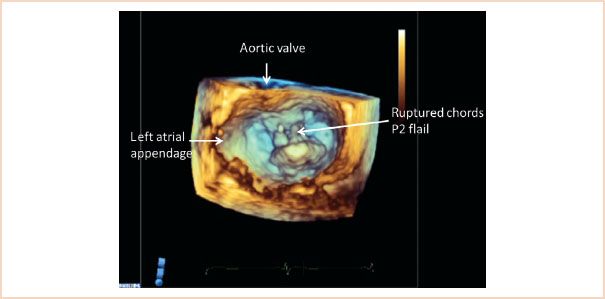
FIGURE 10.11 Three-dimensional view of the mitral valve viewed from the left atrial perspective, with the aortic valve positioned superiorly. The left atrial appendage is also identified. The image is taken in systole, and a flail P2 segment with ruptured chords is clearly recognizable.
In examining the structure of the mitral apparatus it is important to identify and quantify the presence and severity of calcification of the mitral apparatus, especially on the annulus and leaflets. Calcification has a characteristic echodense appearance on echo and is not difficult to identify (Fig. 10.12). Because of shadowing artifacts, however, it may impede visualization of other structures.
Quantitative measurements: In the preoperative structural assessment of the mitral apparatus, a number of echocardiographic measurements should be made, as these are important firstly in assessing whether the valve is amenable to repair and secondly in helping to determine the correct repair technique.
FIGURE 10.12 Calcification. This ME LAX view shows a calcified segment of the posterior leaflet, and this echodense and thickened segment of calcification creates a shadow artifact underneath which impedes visualization of underlying structures.
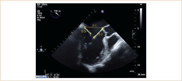
FIGURE 10.13 ME LAX view through A2, P2, ensure that a true ME LAX view is achieved, that is, no foreshortening, and avoiding an oblique slice through the aortic valve and left ventricular outflow tract. Measurements are made in diastole, annulus (D1), length of anterior leaflet (D2), and posterior leaflet length (D3).
Size of Mitral Annulus
The normal mitral annulus is not round, rather it is described as saddle-shaped, and the ratio between the transverse and anteroposterior diameters is approximately 4:3. When the annulus dilates, however, it expands predominantly in the anteroposterior direction, thus reducing the normal 4:3 ratio, as its fibroelastic skeleton is weakest around the posterior annulus. To assess for mitral annular dilatation the annulus is therefore measured in its anteroposterior diameter between the base of the A2 and P2 segments at the level of the mitral annulus. This is done in diastole using the ME LAX view (21), (Fig. 10.13).
Length of Anterior Mitral Leaflet
This is a particularly important measurement to make in the setting of mitral repair and is used to determine the size of the annuloplasty ring to be implanted. The length is best measured during diastole using the ME LAX view with the measurement made from the base of the anterior leaflet (at the annulus) to its leaflet tip (21), (Fig. 10.13). Because of the semicircular shape of the anterior leaflet, the measurement along the A2 segment in this image plane will be the longest. Care should be taken not to include the primary chordae in the measurement, which attach to the tip of the leaflet.
Length of Posterior Mitral Leaflet
This can be measured using the same ME LAX image used for the annulus and anterior leaflet (21), (Fig. 10.13). Measurement is made from the base of the leaflet at the annulus to the tip of the posterior leaflet. The main significance of this measurement is in predicting the likelihood of systolic anterior motion (SAM) of the anterior leaflet occurring postoperatively, as discussed later.
C-sept Distance
The distance from the coaptation point of the mitral leaflets to the septum is also useful in the risk assessment for SAM postrepair. This measurement should be made again in the ME LAX view, this time in systole, so that the leaflets have coapted. The shortest direct distance from the coaptation point to the septum is measured (Fig. 10.14).
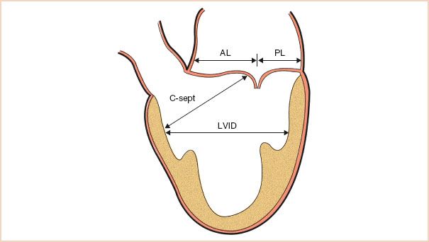
FIGURE 10.14 Schematic demonstrating the transesophageal echocardiographic measurements used before repair to assess the risk for systolic anterior motion. AL, anterior leaflet length; PL, posterior leaflet length; C-sept, distance from the coaptation point to the septum; LVID, left ventricular internal diameter in systole. (Adapted from Maslow AD, Regan MM, Haering JM, et al. Echocardiographic predictors of left ventricular outflow tract obstruction and systolic anterior motion of the mitral valve after mitral valve reconstruction for myxomatous valve disease. J Am Coll Cardiol. 1999;34:2096–2104.)
Left Ventricular End-systolic Internal Diameter
This is best measured using the TG two-chamber view, with systole timed according to MV closure. The long axis of the LV should be horizontal in the image and measurement is made at the level of the chordae from endocardial edge to endocardial edge (Fig. 10.15). For improved accuracy an average measurement from a number of cardiac cycles should be obtained, especially in the case of arrhythmia. A measurement greater than 40 mm defines LV dilatation. The ME two-chamber view can also be used (15).
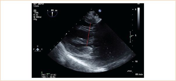
FIGURE 10.15 Left ventricular end-systolic internal diameter. Here measured in the TG two-chamber view, the ME two-chamber view is also suitable. The measurement is made in end systole, at the level of the chordae tendinae, from endocardial edge to endocardial edge, that is, the red line in this figure.
Left Ventricular End-diastolic Internal Diameter:
Left ventricular end-diastolic internal diameter can also be measured using either the TG or ME two-chamber view, this time at end-diastole. Measurements are made at the level of the chordae, and greater than 55 mm represents LV dilatation (15).
Tenting Height
Also referred to as coaptation depth, this is a very important measurement to make, as a preoperative tenting height of 11 mm or higher is associated with poor repair results, and so is usually taken as an indication for MV replacement rather than repair (22,23). This usually occurs in the setting of Carpentier type IIIb pathology, where the left ventricle is dilated and the consequent restriction of the MV leaflets in systole means that they coapt below the level of the mitral annulus. The measurement should be made in the ME LAX or ME four-chamber views in systole. Using the zoom function over the MV or reducing the image depth reduces the percentage error of the measurement. To make this measurement, the level of the mitral annulus is first identified by marking the annular plane. The tenting height is the perpendicular distance from this line marking the annulus level to the coaptation point (Fig. 10.16).
Tenting Area
Similar to tenting height this is measured using the ME LAX view in systole. Tenting area is that area which is enclosed by the line drawn between anterior and posterior annulus and the valve leaflets (Fig. 10.17). An area of >2.5 cm2 is unfavorable for MV repair in functional MR (19).
Coaptation Length
This represents the extent to which both leaflets come to oppose each other during systole. It is measured at end systole in ME LAX views (Fig. 10.18). It is perhaps more important to measure postrepair, as it is one of the fundamental goals of repair, and good coaptation length is associated with better repair durability and long-term results. Usually the coaptation length is longer following implantation of artificial chords as compared to leaflet resection (24).
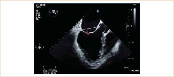
FIGURE 10.16 Tenting height. Useful in helping to determine whether a valve is repairable in functional disease. Measure in late systole using the ME LAX when the leaflets have coapted. Identify the plane of the mitral annulus (white line); the tenting height is the perpendicular distance from the coaptation point to this line (red arrow).
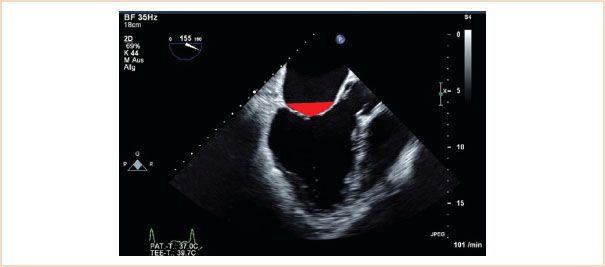
FIGURE 10.17 Tenting area. Using the same view as for tenting height, measure the area enclosed by the line along the annular plane and the atrial sides of both valve leaflets (red triangle).
2. Carpentier Classification System
Functional classification of the leaflets has implications in determining the likelihood of valve repair as will be discussed later. The functional classification of the MV is based on leaflet motion. In type I dysfunction the motion of the leaflets is normal, in type II it is excessive, and in type III it is restrictive (Fig. 10.19). Type III is further subclassified as type IIIa (structural) with restricted motion during both systole and diastole due to leaflet damage (calcification or rheumatic disease) and type IIIb (functional) where the restriction is limited to systole and is due to tethering of the leaflets (ischemic or dilated cardiomyopathy).
Application of CFD is helpful in determining the functional classification. In type I the regurgitant jet is usually central. In type II with one leaflet involved the regurgitant jet is eccentric and directed over the noninvolved leaflet (Fig. 10.20, Videos 10.5–10.11). However, if both leaflets are involved the regurgitant jet can be central. In type III dysfunction, usually, the regurgitant jet is central because most often both leaflets are affected (Videos 10.12–10.16). With only one leaflet involved the regurgitant jet is eccentric and directed over the affected leaflet (Fig. 10.21). In addition, in type II dysfunction, one has to discriminate between billowing, prolapse, and flail (19,21).
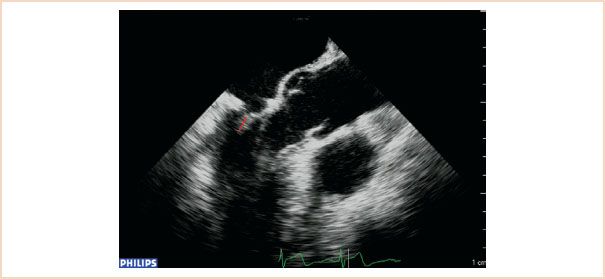
FIGURE 10.18 Coaptation length (shown as red line). Using either the ME LAX or ME four-chamber views, measure the length of apposition between the anterior and posterior leaflets in end systole.
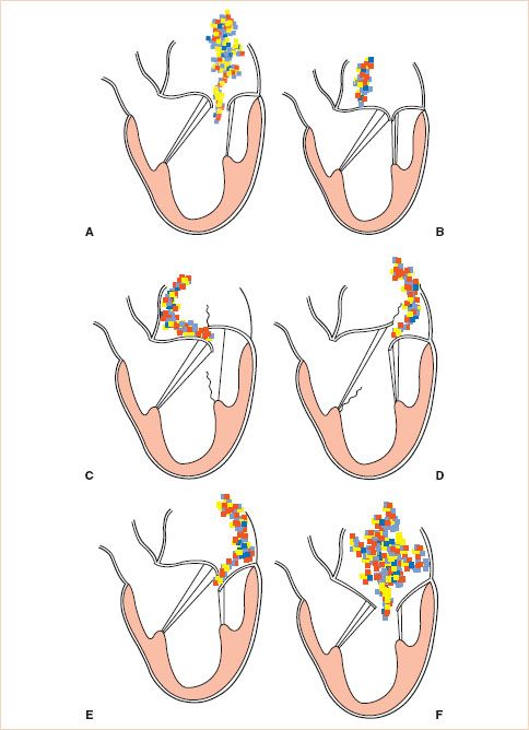
FIGURE 10.19 Carpentier’s classification of mitral regurgitation (MR) based on leaflet motion. In type I, the leaflet motion is normal and the MR jet tends to be central (A,B). In type II, there is excessive leaflet motion and the MR jet is typically directed away from the diseased leaflet (C,D). In type III lesions, the leaflet motion is restricted leaflet motion and is further subdivided into type IIIa (structural) (E) and type IIIb (functional) (F). In type III lesions, the regurgitant jet may be directed towards the diseased leaflet if only one leaflet is affected, or it may be central if both mitral leaflets are equally affected. (Courtesy Dr. Gregory M. Hirsch.)
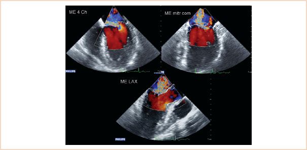
FIGURE 10.20 Color flow Doppler of type II regurgitation, caused by excessive leaflet motion, in this case prolapse affecting the P2 segment. The resulting jet is eccentric and blood is directed over the corresponding, nonaffected (A2) leaflet.
1. Billowing is defined as motion of the body of the leaflets above the mitral annulus plane (Fig. 10.22). To some degree it is a normal finding. It is abnormal when >2 mm in ME LAX view or >5 mm in ME four-chamber view. It is generally associated with excessive tissue, chordal elongation, and possibly later occurrence of leaflet prolapse (Videos 10.17, 10.18).
2. Prolapse describes displacement of one or both leaflet edges above the plane of the mitral annulus where the free margin is directed to the LV (Fig. 10.23). It is often associated with chordal elongation but can also be associated with chordal rupture (Videos 10.5–10.11). The regurgitant jet seen with CFD is always directed over the noninvolved segments in patients with type II dysfunction (Fig. 10.20, Videos 10.6, 10.7, 10.9).
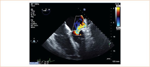
FIGURE 10.21 Color flow Doppler of regurgitation caused by restrictive leaflet motion. The posterior leaflet in this case is restricted and does not move to coapt normally. The resulting jet is eccentric and directed over the affected posterior leaflet.
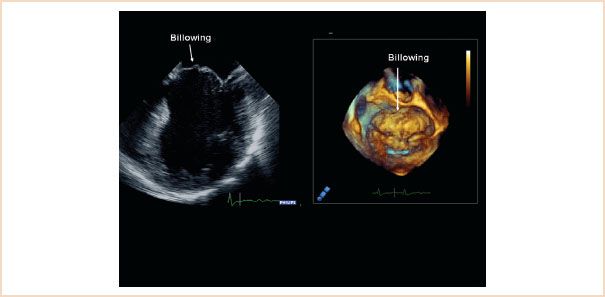
FIGURE 10.22 ME four-chamber view (left) and 3D en face view of the mitral valve from the left atrium (right) both showing extensive billowing of the anterior mitral leaflet. The body of the leaflet, but not its free edge, is pushed over the level of the mitral annulus.
3. Flail is defined as displacement of the free edge of one or both leaflets above the mitral annular plane, where the free edge of the leaflet is also directed into the left atrium (Fig. 10.24, Videos 10.19–10.21). It is often associated with chordal rupture but can also be associated with extreme elongation of the chords.
3. Assessment of the Severity of the Mitral Valve Regurgitation
The severity of the MV regurgitation is practically best assessed using the vena contracta width, the flow convergence (or PISA) method, and the pattern of pulmonary venous flow, as described in Chapter 8, Mitral Regurgitation.
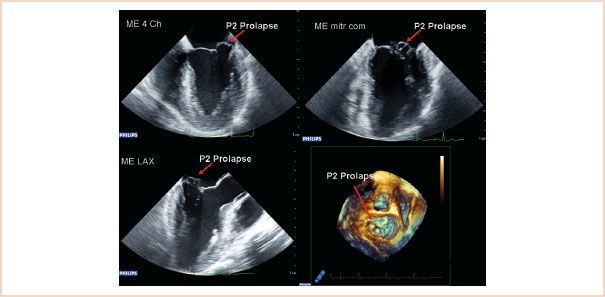
FIGURE 10.23 Two-dimensional ME images: four-chamber (top left), commissural (top right), LAX (bottom left), and 3D en face view of the mitral valve from the left atrium, showing prolapse of the P2 segment. The P1 segment is not visible in this 3D view.
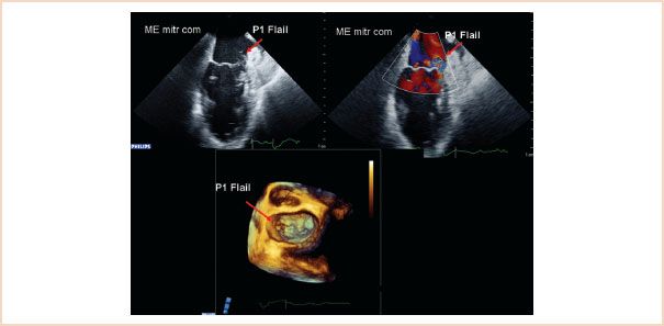
FIGURE 10.24 Two-dimensional ME commissural view (above left) and with color Doppler (above right), and 3D en face view of the mitral valve from the left atrium, showing a flail P1 segment. The reason for the flail is chordal rupture; the remaining segments of chordae attached to the segment also flail over the level of the mitral annulus and point up in the direction of the left atrium.
4. Visualization of the Circumflex Coronary Artery and its Relationship to the Mitral Valve Annulus
Damage or distortion of the circumflex coronary artery caused by the annuloplasty ring or prosthetic valve sutures is a well recognized and potentially devastating complication which occurs in up to 1.8% of patients undergoing MV surgery (25–27). Visualization of the circumflex coronary artery by TEE can be accomplished in most patients by starting from the ME LAX view of the aortic valve and gradually turning the probe to the left (28). From the origin of the left main coronary artery, one can follow the course to the bifurcation into the left anterior descending artery and the circumflex coronary artery by turning the probe to the patient’s left. Further turning of the probe will visualize the course of the circumflex along the mitral annulus (Fig. 10.25, Video 10.22). The circumflex coronary artery must be distinguished from the coronary sinus, a venous structure that runs in a parallel direction to it, and noting that the circumflex coronary artery decreases in diameter along its course from its point of origin, while the coronary sinus increases in diameter, will help to differentiate the two (29). The distance of the circumflex coronary artery from the mitral annulus can also be measured and this information may directly help the surgeon. The preoperative visualization of the circumflex coronary artery acts as a reference for the postrepair visualization.
5. Define Secondary and Coexisting Abnormalities of Other Cardiac Structures
It is recommended that a comprehensive TEE examination be performed both pre- and post bypass in patients undergoing MV repair. In addition to defining the pathology and severity of the MV regurgitation, it is important to examine for echocardiographic evidence of secondary features of MR and also to identify any other coexisting cardiac pathology.
Assessment of LV global and regional systolic function and chamber size has been discussed already and is important to quantify prebypass as a reference for the postoperative examination. Attention should also be paid to the aorta, specifically looking for the presence of atherosclerotic plaque which, if present, increases the risk of postoperative cerebrovascular events. Ascending aortic plaque or calcification increases the risk of complications arising from aortic cannulation and cross-clamping, and if present, these may warrant alteration of surgical technique (30). Plaque in the descending aorta becomes more relevant if a retrograde perfusion technique is used, as in some minimally invasive techniques.
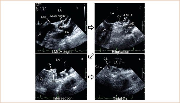
FIGURE 10.25 Visualization of the circumflex artery. LA, left atrium; LMCA, left main coronary artery; AML, anterior mitral leaflet; Ao, aortic sinus; PA, pulmonary artery; Cx, circumflex artery; LAD, left anterior descending; CS, coronary sinus. (Adapted from Ender J, Singh R, Nakahira J, et al. Echo didactic: Visualization of the circumflex artery in the perioperative setting with transesophageal echocardiography. Anesth Analg. 2012;115(1):22–26, with permission.)
Related posts:
 A Practical Approach to the Echocardiographic Evaluation of Ventricular Diastolic Function
 Prosthetic Valves
Stay updated, free articles. Join our Telegram channel

Full access? Get Clinical Tree


