Echocardiography for Percutaneous Aortic Valve and Mitral Clip Implantation
INTRODUCTION
The most frequent valvular disease in adults is calcification of the aortic valve. The average age of patients presenting for surgery has increased to 70 years or older and many are asymptomatic until late in the disease process. Medically treated patients with symptomatic aortic stenosis (AS) show poor survival after occurrence of symptoms (25% at first year and 50% in second year), and the incidence of sudden death approaches 50%. Iung et al. (1) have shown that surgery is denied in 30% of octogenarians predominantly due to a low LV ejection fraction and associated comorbidities (2). Transcatheter aortic valve implantation (TAVI) is an innovative and evolving alternative for elderly, high-risk patients suffering with severe, symptomatic AS (3,4).
The first human TAVI was performed in 2002 using a balloon-expandable pericardial stent via the antegrade approach (5). This led to a series of trials establishing TAVI as a feasible and effective option for multimorbid patients with symptomatic aortic valve stenosis who were denied surgical aortic valve replacement (4,6–8).
CURRENT DEVICES: VALVES AND DELIVERY SYSTEMS
The greatest experience with TAVI has been with the SAPIEN valve (Edwards Lifesciences, Inc., Irvine, CA) and the CoreValve (Medtronic, Inc., Minneapolis, MN). Both of these percutaneous valve delivery systems offer the advantage of avoiding usage of cardiopulmonary bypass (CPB). Ongoing trials continue to explore new options for transcatheter valve systems aimed at improving the mechanism of implantation, the valve and stent material, valve hemodynamics, lowering the incidence of paravalvular leakage, and providing improved mechanisms to retrieve the valve after deployment.
The SAPIEN valve is a balloon-expandable system on a stainless steel stent, into which a trileaflet bovine pericardial valve is mounted (Fig. 16.1). The stents are skirted with a polyethylene terephthalate material designed to decrease paravalvular leaks. The cobalt–chromium alloy allows for better apposition into the annulus and walls of the aorta. The SAPIEN valve is available in three sizes (23, 26, and 29 mm) in Europe and two sizes (23 and 26 mm) in the United States. Currently, the NovaFlex delivery system utilizes an 18-French (Fr) sheath for valve deployment.
The CoreValve is inserted by a retrograde approach using either transfemoral, subclavian, or direct aortic access (Fig. 16.2). The valve consists of a porcine pericardial tissue mounted on a nitinol stent. It consists of three parts (low, middle, and high) and three sizes 26, 29, and 31 mm. The lowest portion corresponds to the annular region and applies the highest radial force to prevent device migration. The middle portion lies within the sinus of Valsalva and is designed to reduce the incidence of paravalvular leaks. The higher portion increases the quality of fixation into the ascending aorta. With progressive design improvements, the delivery system has been reduced in size from the initial 25-Fr to an 18-Fr sheath which may decrease vascular complications. The valve is partially retrievable, repositionable, and excludes the need for rapid pacing during implantation.
Recently, the JenaValve (JenaValve Technology, Munich, Germany) and Acurate valve (Symetis, Inc., Lausanne, Switzerland) obtained CE approval for transapical implantation (9).
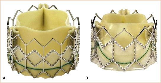
FIGURE 16.1 The Edwards SAPIEN (Edwards Lifesciences, Inc., Irving, CA) is a low-profile valve available in three sizes: 23, 26, and 29 mm catering to annulus sizes between 18 and 27 mm. These valves are pretreated with Carpentier-Edwards ThermaFix process and are presumed to prevent calcification and improve durability. A: Edwards SAPIEN valve. B: The Edwards SAPIEN-XT valve. (Courtesy of Edwards Lifesciences, Inc., Irving, CA.)
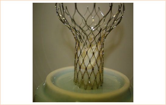
FIGURE 16.2 The CoreValve (Medtronic, Inc., Minneapolis, MN) has three parts (lower, middle, and higher) and three sizes 26, 29, and 31 mm. The valve is partially retrievable with facility to recapture. (Courtesy of Medtronic, Inc., Minneapolis, MN.)
PROCEDURAL PERFORMANCE
Transapical Aortic Valve Implantation
This approach is through the left ventricular apex via a left anterior thoracotomy incision. After insertion of rescue access, (guidewires and sheath for emergency initiation of CPB), an aortic root pigtail catheter is placed in the ascending aorta to angiographically determine aortic root disease, cusp and root anatomy, and ascending aortic dimensions. The apex of the heart is prepared with purse string/mattress sutures, and bipolar epicardial pacing wires are placed for rapid ventricular pacing (RVP) required during valve implantation. Apical access is established and guidewires are placed and subsequently exchanged with an apical sheath and balloon valvuloplasty catheter. Balloon aortic valvuloplasty is performed using RVP (usually 180 to 200 beats/min), the apical sheath is withdrawn, and the valve delivery system is introduced through the apical access. After correct valve position is confirmed by fluoroscopy and TEE, a second episode of RVP facilitates valve implantation. Optimal positioning and valve deployment are then achieved using either fluoroscopy, multidetector computerized tomography (MDCT), or TEE (10).
Transfemoral Aortic Valve Implantation
The transfemoral approach is considered in patients when the anatomy of the iliac vessels is favorable for the insertion of the delivery system. Femoral access is achieved using the contralateral approach and multiple progressive dilations may be required to accommodate the large deployment sheath which is then fixed in place with a stay suture. A pigtail catheter is placed in the abdominal aorta for continuous arterial monitoring and angiographic facilitation of the anatomy of iliofemoral vessels. Pacing leads may be inserted via the internal jugular or femoral veins. After guidewire insertion, a 14-Fr sheath is introduced. A J-tip guidewire is positioned cross the native aortic valve and is then replaced with an Amplatz Super Stiff (260 cm) guidewire. Balloon valvuloplasty is then performed using RVP. The delivery system (RetroFlex for CoreValve) along with the crimped valve is directed toward the annulus of the native valve using fluoroscopic guidance. After satisfactory positioning using central and coaxial orientation, valve deployment is performed. When the Edwards Sapien prosthesis is used a second episode of RVP is required. Correct positioning is achieved by full root angiographic evaluation. After satisfactory implantation of the valve, the delivery system along with the guidewire is withdrawn, femoral access is repaired, and a pressure bandage is applied (11,12).
Transaortic Approach
In this retrograde access, the valve is employed through a ministernotomy incision or a right minithoracotomy in the second or third intercostal space (13,14). Both self-expanding and balloon-expandable valves have been deployed using this method. This approach offers the surgeon easier manipulation and better control of the valve delivery system. Postoperative pain control is better due to a smaller incision compared to transapical access.
ECHOCARDIOGRAPHIC CONSIDERATIONS DURING TAVI
TEE is an essential tool to guide deployment of transcatheter aortic valves (15,16). Given the risk of acute kidney injury with iodinated contrast administration required during angiography, intraoperative TEE may emerge as the primary modality used for TAVI (17–19).
The advanced echocardiographer involved with the TEE guidance for the TAVI procedure must be familiar with the nuances of TAVI deployment. Patients undergoing TAVI tend to be elderly, with multiple comorbidities, and thus, vigilance must be maintained by the anesthesiologists when performing both the clinical care and TEE guidance for the TAVI procedure.
TEE is used for both transfemoral and transapical deployment, but with transfemoral procedures increasingly being performed under local anesthesia combined with conscious sedation (20), the role of TEE in this setting may decrease, though transnasal or intracardiac TEE may allow prolonged monitoring even without general anesthesia (21). During transapical aortic valve implantation, the surgeon has very limited direct visualization of the heart, so imaging plays a pivotal role during the entire procedure. TEE, intraoperative angiography, and intraoperative rotational MDCT scanning are the imaging armamentarium at the surgeon’s disposal in the hybrid operating room. However, the utility of intraoperative TEE is complementary to the other imaging modalities used in the operating room.
A PRACTICAL APPROACH TO TAVI TEE DEPLOYMENT GUIDANCE
As the procedure involves an elderly high-risk population, a comprehensive initial examination is performed. Following the initial comprehensive examination, focus shifts to the aortic valve and then aortic root, corresponding to the sequence of the procedure.
Step 1: Annulus Measurement
This is a critical first step before commencing with TAVI, as faulty measurements can lead to serious complications. When measuring the annulus the echocardiographer has to bear in mind the concept of “oversizing,” by which, for example, a 25-mm valve will be selected for a 23-mm aortic annulus. This approach is justified as that these valves are sutureless and hence need an anchoring sheath or landing zone to prevent the valve from being dislodged. The heavily calcified and stenosed native valve provides the ideal environment and facilitates implantation. Unfortunately, bulky and eccentric calcification poses an increased risk for a paravalular leakage. While standard multiplane TEE can be used to measure the annulus, real-time, three-dimensional (3D) TEE in a biplane mode provides simultaneous long- and short-axis views of the valve and annulus which may improve the accuracy of these measurements. The observer starts from the ME AV LAX view, placing the cursor in the middle to transect the aortic valve. With 3D, the biplane view is used to generate the corresponding short-axis view ME AV SAX in the orthogonal plane (Fig. 16.3, Video 16.1). The ME AV SAX view should demonstrate all three commissures along with the base of any calcified leaflet, which further ensures a true short-axis plane. The annulus of the aortic valve and aortic root is then measured in the long and short axis in systole. With standard two-dimensional (2D) TEE, the annulus is generally measured from the ME LAX view, with the short-axis plane viewed by rotating the plane to ~40 to 50 degrees. To avoid underestimates of annual size, it is important to identify the true annulus, rather than the common overlying calcification. Measurements (trailing edge to leading edge) are made in systole at the AV leaflet insertion sites (hinge points) within the left ventricular outflow tract. Alternatively, the annulus can be measured with postprocessing using commercial software from a full 3D volume data set obtained in the ME AV LAX view, but owing to time constraints in the operating room, this currently is more for research purposes. In the future, improvements in automated 3D echo processing should allow rapid extraction of annular anatomy.
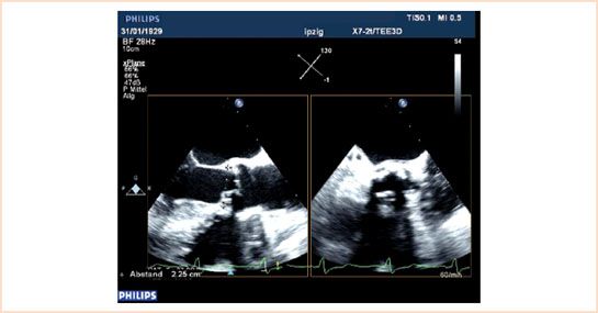
FIGURE 16.3 Annulus can be reliably measured using biplane technique. The measurements are done at the aortic valve insertion sites (hinge points) within the left ventricular outflow tract from trailing edge to leading edge.
Step 2: Guidewire Placement
We suggest that the ME AV LAX view be used to position the guidewire. For transapical TAVI, this view is adjusted to focus on the LV apex, the mitral valve (MV) and its subvalvular apparatus, the aortic valve and annulus, the sinus and sinotubular junction, and the proximal part of the ascending aorta. The probe is manipulated using the lateral and retroflex controls to fully image the apex by identifying the longest long-axis dimension of the LV.
Complications that can occur during transapical TAVI include the following:
1. Nonapical punctures can be avoided by echo-guided digital palpation of the apex before proceeding with the puncture.
2. Guidewire entrapped in the secondary chords of the MV (Video 16.2).
3. Guidewire is not able to align with the aortic valve and reaches the left atrium (Video 16.3) or has a difficult alignment owing to a hypertrophied LV (Video 16.4). By utilizing ME AV LAX view (Fig 16.4), one can ascertain the degree of septal hypertrophy (Video 16.5) and be prepared to take precautionary measures to avoid “physiologic” systolic anterior motion (SAM) (22). Despite the fact that placement of the guidewire is more straightforward using the transfemoral approach, TEE may still be helpful during this approach.
Step 3: Stage of Balloon Valvuloplasty
After the guidewire is positioned and exchanged with a Super Stiff guidewire, the balloon is loaded and positioned for valvuloplasty. Biplane TEE imaging is ideal for this purpose as the balloon needs to be positioned midvalve for universal and complete dilation of the calcified valve (Video 16.6). The presence of eccentric calcification as opposed to regular calcification (Video 16.7a,b) may predispose for postimplantation paravalvular leak. The presence of calcified plaques in the region of right coronary ostium can be seen well in 2D and real-time 3D TEE (Fig. 16.5A,B). Rupture or sliding of the balloon during valvuloplasty (Video 16.8) necessitates another episode of valvuloplasty with a bigger balloon (Video 16.9) before valve implantation. Balloon valvuloplasty may cause aortic regurgitation (Video 16.10) which may require a change in inotrope management. The phase following valvuloplasty should be brief to prevent acute ventricular failure and the valve should be deployed immediately after the ballooning phase. If general anesthesia is used for the transfemoral approach, TEE can be helpful in placement of the pigtail catheter used to guide valve placement (Video 16.11).
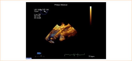
FIGURE 16.4 Placement of guidewire: Surrounding structures include the anterior mitral leaflet, subvalvular apparatus, secondary chords of mitral valve and septal hypertrophy need to be monitored during insertion of guidewire. ME AV LAX view in live 3D-TEE mode may be beneficial for quick and accurate assessment.
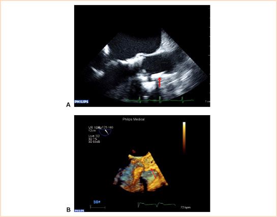
FIGURE 16.5 A and B: Presence of calcified plaques in front of ostium of right coronary artery. Echocardiographer should be alert of a new regional wall motion abnormality post balloon aortic valvuloplasty or after the implantation of the new valve. Arrow showing the presence of calcium before right coronary ostium in both 2D (Fig. 16.5A) and 3D images (Fig. 16.5B).
Step 4: Stage of Valve Implantation
After the insertion of the applicator device along with the valve, the valve position is determined by TEE and angiography. The exchange of guidewires and insertion of the applicator device may cause a sudden air entry into the heart and should be evaluated (Video 16.12). When implanting a CoreValve, TEE should confirm that the nitinol stent is well within the borders of the calcified native annulus. The CoreValve frame has a longer length and can vary from 52 to 55 mm depending on the valve size. However, an aortic dimension above 43 mm is a contraindication for CoreValve implantation due to the risk of the device being dislodged or migrating after implantation. The SAPIEN valve should be positioned at midannulus, (Video 16.13), and for the XT valve, slightly more than half should be below the annulus (Figs. 16.1 and Figs. 16.6). Echocardiographers involved in implantation guidance need to familiarize themselves with the structure of the implantable valves and their delivery systems to ensure that these landmarks are identified during the procedure.
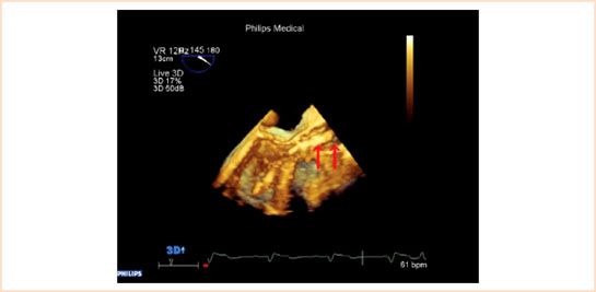
FIGURE 16.6 Real-time 3D allows depth perception which cannot be appreciated in 2D. The crimped SAPIEN valve before deployment is imaged in this figure. The arrow on the left of the picture shows the distal end of the valve whereas the arrow on the right demonstrates the tip of the delivery system.
Related posts:
Stay updated, free articles. Join our Telegram channel

Full access? Get Clinical Tree


