Two-dimensional Examination
OVER THE LAST FEW YEARS there has been a great deal of emphasis on three-dimensional (3D) imaging and new technology in general. Although it is easy to get caught up in the wave of excitement, not every OR has a 3D machine and it will be a few years before this technology is ubiquitous and simple to use in all clinical scenarios. Two-dimensional imaging remains the key clinical tool for intraoperative echocardiographic imaging in the majority of clinical situations.
The purpose of this chapter is to demystify echocardiographic image orientation and provide a stepwise approach to image acquisition. In the eyes of the novice, learning and applying transesophageal echocardiography (TEE) may seem like an insurmountable task. With the use of this stepwise approach, TEE will quickly become an integral part of your practice and a valuable aid for intraoperative decision-making (1–6).
IMAGING PLANES AND ORIENTATION
Understanding the orientation of the imaging plane is crucial for both acquisition of the desired images and correct interpretation of the displayed cardiac anatomy. Although TEE is limited to the confines of the esophagus and stomach, the ability to alter the position and orientation of the ultrasound beam allows a broad view of the cardiac anatomy.
PROBE INSERTION
The TEE probe is passed into the esophagus in the same manner in which an orogastric tube is placed. The easiest way to insert the probe is to perform a jaw lift by grabbing the mandible with the left hand and inserting the probe with the right. The probe is inserted with constant gentle pressure in addition to a slight turning back and forth and from left to right to find the esophageal opening. If resistance is encountered, the cause most often is excessive extension of the head and neck. Advancement of the probe is stopped after the head of the probe has passed the larynx and cricopharyngeus muscle, where a distinct loss of resistance is felt. The imaging head will lie in the upper esophagus.
PROBE MANIPULATION
The position and orientation of the TEE probe can be altered by several types of manipulation (Fig. 2.1, Video 2.1). By gripping the probe shaft near its entrance in the mouth, the probe can be advanced or withdrawn. The degree of insertion can be easily determined by the depth markings imprinted on the shaft. For cardiac imaging, the probe position ranges from the upper esophagus to the stomach. In the upper esophagus, the structure closest to the TEE probe is one of the great vessels. In the midesophagus (ME), the structure closest to the TEE probe is the left atrium, and in the transgastric (TG) position, the structure closest to the TEE probe is (most commonly) the left ventricle. Therefore, depending on the depth of insertion, the structure at the apex of the imaging sector will be one of the great vessels, the left atrium, or the left ventricle.
The orientation of the ultrasound beam can be further adjusted by manually turning the probe shaft to the left or right. The probe can be anteflexed or retroflexed by using the large knob on the probe handle. The small knob on the probe handle will flex the probe leftward or rightward. These maneuvers allow precise user control over the direction of the ultrasound beam to visualize the structure of interest.
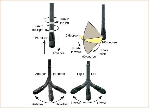
FIGURE 2.1 Terminology used to describe manipulation of the probe and transducer during image acquisition. (From Shanewise JS, Cheung AT, Aronson S, et al. ASE/SCA guidelines for performing a comprehensive intraoperative multiplane transesophageal echocardiographic examination: Recommendations of the American Society of Echocardiography Council for Intraoperative Echocardiography and the Society of Cardiovascular Anesthesiologists Task Force for Certification in Perioperative Transesophageal Echocardiography. Anesth Analg. 1999;89:870–884, with permission.)
MULTIPLANE IMAGING ANGLE
The first clinically useful TEE probes were capable of producing a single or monoplane cross section of the heart. This imaging plane is generated perpendicular to the shaft of the probe and corresponds to the typical transverse views obtained with transthoracic echocardiography. The biplane probes of the next generation were able to produce two perpendicular views: The standard transverse cross sections and a longitudinal cross section. Currently, most of the probes in use in adult TEE are multiplane probes. Through an electronic switch on the probe handle, the operator selectively rotates the orientation of the imaging plane from 0 degrees (transverse plane) to 180 degrees in 1-degree increments. This capability offers many advantages with respect to image acquisition but can also generate tremendous confusion for novice echocardiographers.
Experts rely on two key points to determine image orientation quickly. First, independent of the imaging plane, the ultrasound beam always originates from the esophagus or stomach and projects perpendicular to the probe. Consequently, on the monitor the apex of the sector displays structures that are closest to the TEE probe. As a general rule of thumb, structures seen near the apex of the image sector (i.e., closest to the TEE probe) will be posterior structures, and those close to the arc of the sector (i.e., more distant from the TEE probe) will be anterior structures.
Second, left and right orientation depends on the degree of rotation of the scan head. A simple way to orient yourself is to place your right hand on your chest with your palm facing downward, your extended thumb pointing leftward and anterior, and your fingers rightward and anterior. This is the orientation of the imaging scan at 0 degrees and the scan lines begin at your fingers sweeping right to left toward your thumb. Consequently, your fingers point toward right heart structures that will be displayed on the left side on the monitor as you look at the screen (Fig. 2.2). Note that this right-to-left display orientation is similar to that of a chest x-ray.
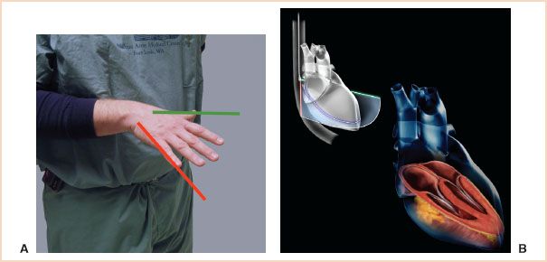
FIGURE 2.2 A: Orientation of your hand, as described in text, for an imaging plane of 0 degrees. The red and green lines correspond with the lines described in B. B: The top figure is a schematic representation of a transesophageal echocardiography (TEE) probe obtaining a midesophageal (ME) four-chamber view. The TEE probe lies in the esophagus posterior to the left atrium. The imaging plane is projected like a wedge anteriorly through the heart. The image is created by multiple scan lines traveling back and forth from the patient’s left (green edge of imaging sector) to the patient’s right (red edge). The resulting image is displayed on the monitor with the green edge of the sector displayed on the right side of the monitor and the red edge on the left. In the bottom image, the schematic is made transparent and the anatomy of the heart is displayed in the orientation seen in an ME four-chamber view.
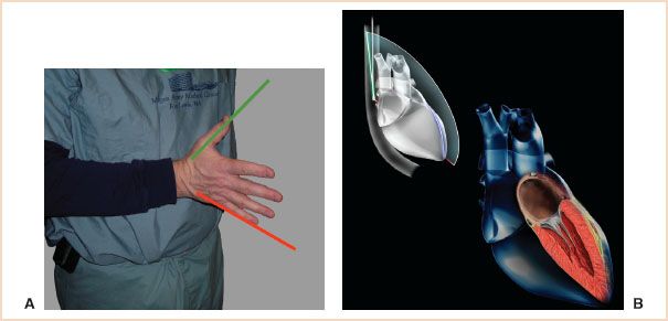
FIGURE 2.3 A: Orientation of your hand, as described in text, for an imaging plane of 90 degrees. The red and green lines correspond with the lines described in B. B: The top figure is a schematic representation of a transesophageal echocardiography (TEE) probe obtaining a midesophageal (ME) two-chamber view. The probe is in the same position as described in Figure 2.2. However, in this case the imaging sector is rotated so that the green sector edge has moved clockwise and is now cephalad, and the red sector edge is now caudad. As previously described, the green edge is displayed on the right side of the monitor’s screen and the red edge on the left. In the bottom image, the schematic is made transparent and the anatomy of the heart is displayed in the orientation seen in an ME two-chamber view.
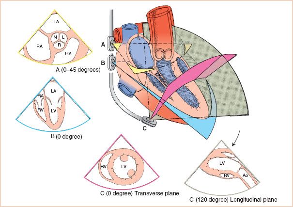
FIGURE 2.4 Through simple manipulations, the transesophageal echocardiography (TEE) probe offers a multifaceted picture of cardiac anatomy. Progressive advancement of the probe in the midesophagus provides a cross-sectional view of the aortic valve (A) followed by a long-axis view of the cardiac chambers (B). Further advancement and anterior flexion of the probe head (C) allow visualization of the left ventricle in the short axis. Rotation of the imaging plane expands the imaging capacity of TEE. In this example, the left ventricle and its outflow tract are brought into view by rotating the imaging plane to 120 degrees. LA, left atrium; RA, right atrium; N, noncoronary cusp; L, left coronary cusp; R, right coronary cusp; RV, right ventricle; LV, left ventricle; Ao, aorta.
Increases in the imaging plane angle proceed in a clockwise manner. For example, when the imaging plane is rotated to 90 degrees, the imaging orientation is mirrored by rotating your hand clockwise 90 degrees (fingers pointing downward) (Fig. 2.3). Therefore, the scan now progresses from posterior to anterior structures (longitudinal plane).
The combination of probe manipulation and imaging plane angle provides a powerful tool for cardiac imaging (Fig. 2.4). For example, slight withdrawal of the probe and rotation of the imaging plane to 40 degrees provides a short-axis view of the aortic valve (Fig. 2.5). In contrast, advancement of the probe into the stomach combined with anteroflexion with the imaging plane at 0 degrees provides a short-axis view of the left ventricle (Fig. 2.6).
GOALS OF THE EXAMINATION
TEE examinations, whether comprehensive or abbreviated, should display all pertinent structures in the heart. Each cardiac chamber and valve should be visualized in at least two orthogonal planes. All segments of the myocardium should also be visualized. This approach helps ensure the diagnosis of any significant abnormalities and minimizes the incorrect identification of artifacts.
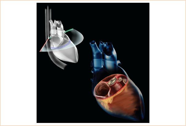
FIGURE 2.5 The top figure is a schematic representation of a transesophageal echocardiography (TEE) probe obtaining a midesophageal (ME) aortic valve short-axis view. The probe is in the esophagus but slightly above the position in Figures 2.2 and 2.3. When the leaflets of the aortic valve are seen, the imaging plane is rotated from 0 degrees to approximately 40 degrees when the aortic valve is seen in a true cross section. The image on the monitor is generated from scan lines going back and forth from the green edge (right side of monitor) to the red edge (left side of monitor). In the bottom image the schematic is made transparent and the anatomy of the heart is displayed in the orientation seen in an ME aortic valve short-axis view.
Echocardiographers differ in their approach to a diagnostic TEE examination. Many prefer to start with those views that examine known pathology. Others believe the examination should first systematically examine for unknown pathology before the area of concern is evaluated. A common approach starts with TG views of the left ventricle because of the frequent abnormalities detected with these views. Each of these approaches has its advantages and disadvantages and there is no one correct way. However, the goal of any approach must be a complete examination of all structures of the heart. A joint task force including members of the American Society of Echocardiography and the Society of Cardiovascular Anesthesiologists has published guidelines for performing a comprehensive intraoperative multiplane TEE examination (7). However, additional views are often required to assess a particular abnormality and no consensus has been reached regarding whether all 20 cross sections described in the guidelines should be acquired in every surgical patient.
The examination described in this chapter is based on progressive esophageal advancement of the probe to evaluate cardiac anatomy and function followed by progressive withdrawal for the evaluation of the aorta. This approach minimizes manipulation of the TEE probe, thereby shortening the examination time. This author has not found the depth of probe insertion to be a reliable tool for identifying intracardiac anatomy. The preferred approach is to report the location of cardiac anatomy/pathology relative to known intracardiac structures and standard cross-sectional views. The progressive advancement/removal of the probe provides a systematic anatomic orientation (avoiding disorientation as to the displayed imaging plane) and allows for easy description of anatomy relative to other cardiac structures. Pathology in the aorta can be referred to the depth of probe insertion but this has more value in the long-term outpatient evaluation of lesions and, we believe, little value in the intraoperative examination.
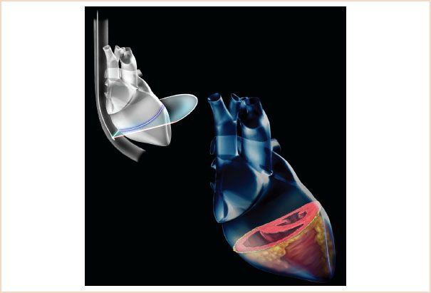
FIGURE 2.6 The top figure is a schematic representation of a transesophageal echocardiography (TEE) probe obtaining a transgastric (TG) midshort-axis view. The probe is advanced into the stomach and anteflexed until solid contact is made with the gastric wall. The imaging plane is projected from the probe at 0 degrees. The image on the monitor is generated from scan lines going back and forth from the green edge (right side of monitor) to the red edge (left side of monitor). In the bottom image, the schematic is made transparent and the anatomy of the heart is displayed in the orientation seen in a TG mid papillary short-axis view.
The Comprehensive Examination
Midesophageal Ascending Aortic Short-axis View
From the initial position following passage into the esophagus, instead of advancing to the aortic valve, the probe is only advanced slightly until the proximal aorta is seen. The probe angle is then rotated until a true short axis is seen, usually between 0 and 45 degrees. The main pulmonary artery is seen bifurcating and the right pulmonary artery will lie posterior and perpendicular to the proximal aorta (Fig. 2.7, Video 2.2).
This view is useful for identifying pulmonary artery catheter placement as well as for visualizing thromboembolism in the pulmonary artery.
Midesophageal Ascending Aortic Long-axis View
From the short-axis view, the probe angle is rotated to visualize the proximal aorta in the long axis. This view may identify the proximal extent of a dissection, may allow for visualization of saphenous vein grafts and can also be used to interrogate the proximal suture line of an ascending aortic tube graft (Fig. 2.8, Video 2.2).
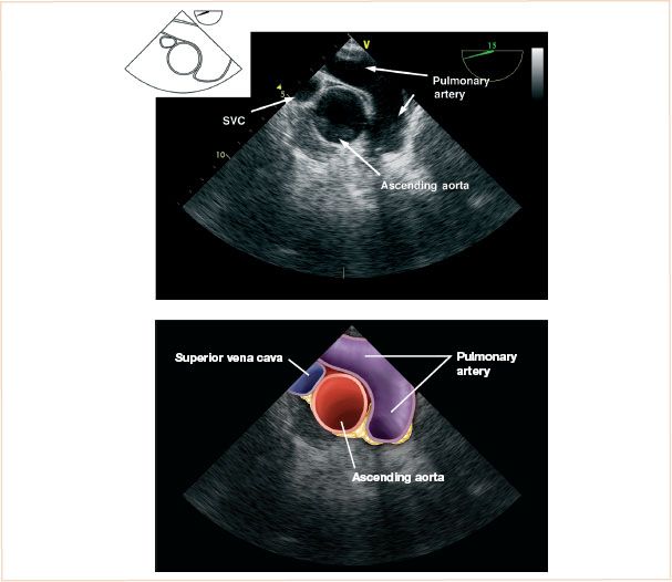
FIGURE 2.7 Midesophageal ascending aortic short-axis view.
Midesophageal Aortic Valve Short-axis View
The probe is advanced until the leaflets of the aortic valve are seen. The imaging plane is then rotated to approximately 45 degrees to obtain the ME aortic valve short-axis view. The size of the aortic valve in comparison with the atrial chambers, in addition to the mobility of the aortic leaflets and any leaflet calcification, are carefully noted.
The primary diagnostic goals of this view are to define the general morphology of the aortic valve (e.g., bicuspid vs. tricuspid) and to determine if aortic stenosis is present. The relative sizes of the aorta and the atria should be noted. The intra-atrial septum can be observed for openings consistent with an atrial septal defect or patent foramen ovale. In addition, look for continuous deviation of the septum away from an atrium with elevated pressures (Fig. 2.9, Video 2.3). If the probe is withdrawn slightly, with small left to right turns, the origins of the left and right coronary arteries can be seen.
Midesophageal Right Ventricular Inflow–Outflow
After completion of the ME short-axis view of the aortic valve, the next three views are obtained at the level of the aortic valve in the longitudinal plane. The first view is the ME right ventricular inflow–outflow view. Start at the ME aortic valve short axis and, without moving the probe, change the rotation of the imaging angle to approximately 60 to 90 degrees. The desired imaging plane will visualize the tricuspid valve, right ventricular outflow tract, and proximal pulmonary artery. Note that the right atrium will be at the 10 o’clock position, the tricuspid valve at the 8 o’clock position, the right ventricular cavity at the 6 o’clock position, and the pulmonary valve and pulmonary artery at the 4 o’clock position.
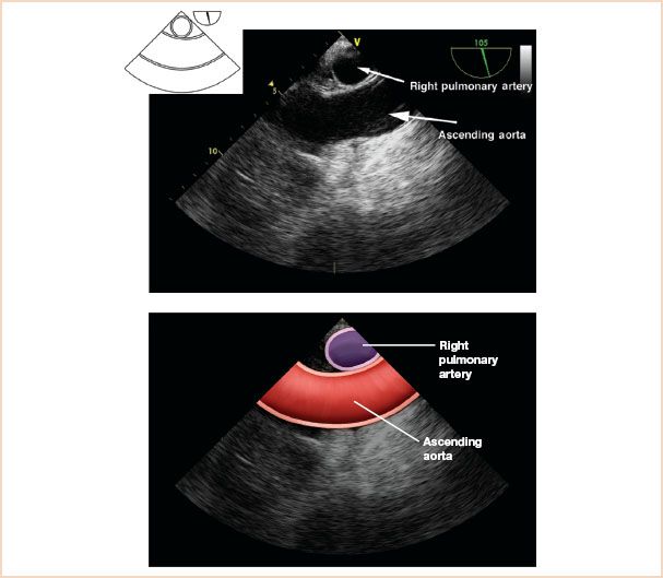
FIGURE 2.8 Midesophageal ascending aortic long-axis view.
The primary diagnostic goals of this view are to gauge the right ventricular chamber and pulmonary valve annulus size and to evaluate the pulmonic valve. This view is often superior to the ME four-chamber view for Doppler interrogation of the tricuspid valve. In adults with prior congenital heart surgery, evaluation of the right ventricular outflow tract and pulmonary valve may provide important diagnostic information.
This view may be helpful in confirming the location of a pulmonary artery catheter if a diagnostic waveform is not identified. The echodense linear pulmonary artery catheter will be seen in the proximal pulmonary artery if the catheter is in the correct location (Fig. 2.10, Video 2.4).
Midesophageal Aortic Valve Long-axis View
The ME aortic valve long-axis view is obtained by further rotating the imaging angle to approximately 110 to 130 degrees. A slight turn of the probe toward the patient’s right may be necessary to optimize this image. The view is complete when the left ventricular outflow tract, aortic valve, and proximal ascending aorta are displayed together. Additional structures to observe are the outflow tract itself, the sinus of Valsalva, and the sinotubular junction.
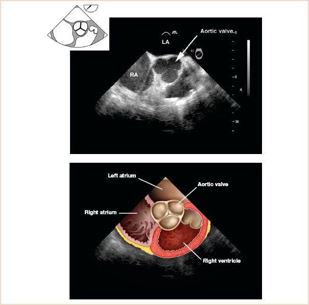
FIGURE 2.9 Midesophageal aortic valve short-axis view.
Related posts:
Stay updated, free articles. Join our Telegram channel

Full access? Get Clinical Tree


