Prosthetic Valves
INTRODUCTION
The first successful artificial heart valves were implanted in 1960. Starr implanted a Starr–Edwards caged-ball valve in a patient with rheumatic mitral stenosis and Harken implanted the Harken caged-ball prosthesis in the subcoronary aortic position in a patient with rheumatic aortic stenosis and regurgitation. Over the next 45 years, numerous manufacturers have produced prosthetic valves of various designs for clinical use. In the past 10 years, increased attention to the risk of prosthetic-patient mismatch has been an important factor driving the development of prosthetic valves with larger effective orifice sizes and thus more favorable hemodynamic properties. The production of prosthetic valves has also become a competitive business with each manufacturer creating unique products and individual cardiac surgeons developing specific preferences in their choice of valves. As a consequence, the design, construction, and marketing of prosthetic valves is an ongoing process and incremental refinements are continually being made in an effort to improve the biocompatibility, durability, hemodynamic performance, and ease of implantation that are evidenced by the frequent appearance of new models with new trade names. One of the challenges of assessing prosthetic valve function is to recognize and appreciate the distinct echocardiographic features and hemodynamic performance of each of the many varieties of prosthetic valve types, models, and sizes that have been commercially available and may be encountered in the existing contemporary patient population.
ROLE OF TRANSESOPHAGEAL ECHOCARDIOGRAPHY IN THE EVALUATION OF PROSTHETIC CARDIAC VALVES
Multiplane transesophageal echocardiography (TEE) is considered the diagnostic technique of choice for identifying the type of prosthesis, assessing its function, and diagnosing prosthetic dysfunction (1–6). The ability of TEE to combine two-dimensional (2D) and three-dimensional (3D) with color Doppler and spectral Doppler imaging enables TEE to generate diagnostic information based on both the structure and the hemodynamic function of the prosthetic valve. However, the evaluation of prosthetic heart valves using ultrasound imaging poses special problems because mechanical valves and components of bioprosthetic valves have poor acoustic properties, making it difficult to image the valve and the surrounding soft tissues in detail. In addition, the small size of the valves and their mechanical components make detailed examination of the motion of the stent and occluder mechanisms challenging.
Despite incremental improvements in instrumentation, the imaging resolution that can be achieved using transthoracic echocardiography (TTE) does not match that achieved by TEE. The improved imaging resolution provided by TEE with the ultrasound transducer close to the cardiac valve structures permits a detailed assessment of both prosthetic valve function and determining the etiology of prosthetic valve dysfunction. High resolution 2D and 3D imaging can distinguish between normal and abnormal motion of the valve leaflets and occluder mechanisms. Abnormal motion of the valve stent or dehiscence of the prosthetic valve annulus can also be detected. In addition, vegetations, calcifications, pannus, and thrombus formation on the prosthetic valve can be detected using 2D and 3D imaging.
Color Doppler imaging can distinguish normal closure and leakage regurgitant jets (washing jets) from pathologic transvalvular or paravalvular regurgitant jets. Quantification of blood flow velocity using spectral Doppler techniques often permits the estimation of transvalvular pressure gradients and the effective orifice area of the prosthetic valves (1,7–10).
TABLE 13.1 Prosthetic Heart Valves and Clinical Indications for TEE
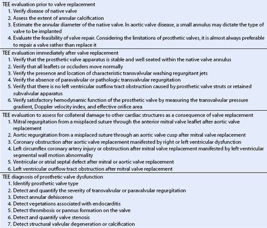
Clinical indications for TEE include the evaluation of the native valve prior to valve replacement, the evaluation of prosthetic valve function immediately after implantation, the diagnosis of prosthetic valve dysfunction, the assessment of prosthetic patient mismatching, and the diagnosis of early complications associated with valve replacement (Table 13.1).
TECHNICAL CONSIDERATIONS IN PERFORMING TEE EXAMINATIONS OF PROSTHETIC VALVES
Many of the ultrasound imaging techniques used to evaluate native valve function can be applied to the evaluation of prosthetic heart valves, but certain special considerations are necessary. Ultrasound does not penetrate through the metallic and polymeric components of mechanical and biologic valves. These material components produce highly specular echoes and impair the imaging of distal structures because of acoustic shadowing. For these reasons, decreasing the transmit gain helps to decrease imaging artifacts and to resolve structural details in the vicinity of nonbiologic materials. To overcome some of the problems created by acoustic shadowing, it is necessary to image the prosthetic valve from different transducer positions that provide views of both the upstream and the downstream sides of the prosthetic valve. For example, the midesophageal aortic valve long-axis imaging plane will not reliably display the motion of the mechanical aortic prosthesis because of shadowing from the valve sewing ring (Fig. 13.1). By advancing the TEE probe to the transgastric position, prosthetic aortic leaflet motion can be observed from the apical or mid-left ventricular transgastric long-axis view through the aortic valve without interference from the sewing ring (Fig. 13.2). Similarly, imaging the ventricular side of mitral prosthetic valves using the transgastric mid-ventricular or deep transgastric long-axis imaging planes provides detail that cannot be observed with the midesophageal views alone.
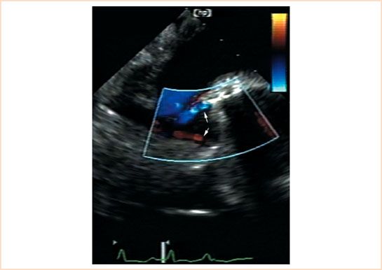
FIGURE 13.1 Bileaflet mechanical prosthesis in the aortic position. Transesophageal echocardiographic midesophageal aortic valve long-axis view at a multiplane angle of 135 degrees in a patient with a bileaflet mechanical prosthesis in the aortic position. Color Doppler flow imaging in diastole shows the normal appearance of the two leakage regurgitant jets that originate at the leaflet hinge points (arrows). Note that ultrasound shadowing caused by the annular stent makes it difficult to assess the motion of the leaflets from this imaging angle. The transgastric long-axis or the deep transgastric long-axis views through the aortic valve are necessary to evaluate the motion of the individual leaflets.
Doppler echocardiography can be used to estimate the transvalvular pressure gradient across bileaflet, tilting disc, and biologic valves that have a centrally directed, linear transvalvular flow. In contrast, for caged-ball or caged-disc valves where the occluder alters the direction of blood flow through the valve, the Bernoulli equation will not accurately estimate the transvalvular pressure gradient.
ECHOCARDIOGRAPHIC CHARACTERISTICS OF THE INDIVIDUAL PROSTHETIC CARDIAC VALVE TYPES
Each type of prosthetic valve has distinct echocardiographic features and hemodynamic characteristics. The type, shape, and motion of the structural components of the valve allow it to be identified by the TEE examination. Knowing the published and manufacturers’ specifications for the normal range of motion of the valve components, the average transvalvular pressure gradient, and average effective orifice area is necessary to verify normal functioning of the prosthesis and to diagnose prosthetic dysfunction (1,8–10). In general, prosthetic valves are classified as mechanical or biologic and by the manufacturer, model number, and outside diameter of the sewing ring (Table 13.2 and Appendix D).
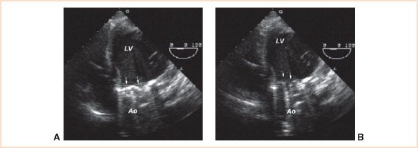
FIGURE 13.2 Bileaflet mechanical prosthesis in the aortic position. Transesophageal echocardiographic deep transgastric apical long-axis view at a multiplane angle of 0 degrees permits imaging of prosthetic valve leaflets (arrows) and their motion. In diastole (panel A), both leaflets are in the fully closed position at an angle of 30 degrees in relation to the plane of the valve annulus. In systole (panel B), both leaflets are in the fully open position at an angle of 90 degrees in relation to the plane of the valve annulus. LV, left ventricle; Ao, aorta.
Mechanical Heart Valves
Mechanical heart valves are more durable than biologic valves, but are thrombogenic and require systemic anticoagulation. For these reasons, mechanical valves are traditionally considered for younger patients who are more likely to experience structural failure after implantation of a biologic prosthetic as a consequence of their longer life expectancy. Mechanical prosthetics may also be preferred in patients who require anticoagulation therapy for other reasons or in whom the risk of re-operation is unacceptable. The silastic, metal, and pyrolytic carbon components of mechanical valves are poor conductors of ultrasound and cause acoustic shadowing, reverberations, and strong specular signals. The echocardiographic appearance and characteristics of mechanical prosthetic valves can be categorized based on the occluder mechanism.
TABLE 13.2 Prosthetic Valve Types
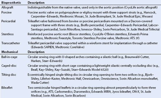
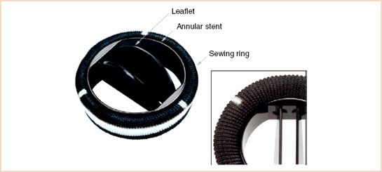
FIGURE 13.3 Photograph of a Carbomedics R-series mechanical bileaflet prosthetic aortic valve. The valve consists of two semicircular pyrolytic carbon leaflets supported within a pyrolytic carbon annular stent surrounded by the sewing ring. The inset shows a close-up of the hinge points of the leaflets. The valve is designed to permit a small amount of leakage backflow at the hinge points.
Bileaflet Valves
The bileaflet mechanical valve prostheses are the most commonly implanted mechanical valves because of their outstanding record of durability and large valve orifice area in relation to sewing ring diameter. They can be implanted in the aortic, mitral, or tricuspid positions. The valves are constructed of two semicircular leaflets suspended from four hinge points in a circular annulus surrounded by a sewing ring (Fig. 13.3). When the leaflets open, three separate orifices are formed within the valve annulus. Minor variations in design include the shape of the leaflets, the width of the sewing ring, and the materials used to construct the valve components.
A systematic TEE examination of the prosthetic valve includes verification of normal leaflet motion, proper seating of the prosthesis within the native valve annulus, and normal blood flow pattern through the valve. In addition, the TEE examination should verify the presence of normal washing jets and the absence of significant paravalvular regurgitation and the absence of abnormal transvalvular regurgitation. Finally, TEE can be used to estimate the transvalvular pressure gradient and calculate the effective orifice area of the valve.
1. Confirm leaflet motion: 2D and 3D imaging confirms the opening and closure of the two mechanical leaflets (Video 13.1). In the short-axis imaging plane, the two leaflets in the open position produce two linear shadows within a circular annulus (Fig. 13.4). For valves implanted in the mitral position, leaflet motion is best examined using the midesophageal long-axis views (Fig. 13.5). Multiplane rotation through the valve to generate a cross-sectional imaging plane that is perpendicular to the two leaflets permits the motion of both leaflets to be observed simultaneously (Fig. 13.5). The two leaflets tilt open symmetrically to an angle of 85 to 90 degrees and close at an angle of 30 degrees in relation to the plane of the annulus for a travel arc of approximately 60 degrees. Leaflet motion of a valve implanted in the aortic position is more difficult to evaluate (Figs. 13.1 and Figs. 13.4). Acoustic shadowing from the sewing ring and leaflets typically obscure leaflet motion in the midesophageal aortic valve long-axis view. Individual leaflet motion is better visualized in the transgastric long axis and deep transgastric long-axis views that provide unobstructed views of the aortic valve in the far field through the left ventricle and left ventricular outflow tract (LVOT) (Figs. 13.2 and Figs. 13.6, Video 13.2).
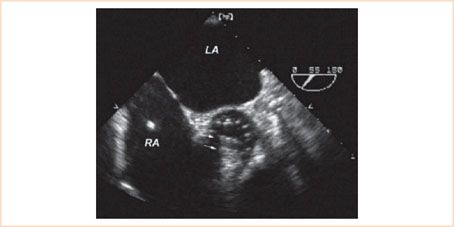
FIGURE 13.4 Bileaflet mechanical prosthesis in the aortic position. Transesophageal echocardiographic midesophageal short-axis image just above the plane of the valve annulus in systole provides cross-sectional imaging of the two parallel leaflets (arrows) of the mechanical valve in the open position. Note the acoustic shadowing caused by the mechanical leaflets in the far field making it difficult to resolve detail in the distal portion of the valve annulus. LA, left atrium; RA, right atrium.
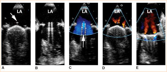
FIGURE 13.5 Multiplane TEE midesophageal images of a normally functioning bileaflet mechanical valve in the mitral position. Panels A and D show the appearance of the prosthetic valve at mid-systole with both leaflets in the closed position at a multiplane angle perpendicular to the pivot axis (two-leaflet view). The arrow in panel A shows the location of the pivot guard that contains the hinge points. Panels B and C show the appearance of the prosthetic valve in diastole with both leaflets in fully opened position at a multiplane angle perpendicular to the pivot axis (two-leaflet view). The arrow in panel C shows the position of the central orifice. Doppler color flow imaging at mid-systole (panels D and E) shows the typical appearance of normal regurgitant jets that originate from the hinge points or between the leaflets and the valve stent. Rotating the multiplane angle 90 degrees forward from the two-leaflet view produces the single-leaflet view that is parallel to the pivot axis (panel E). In the single-leaflet view, Doppler color flow imaging shows the origin of the centrally directed regurgitant jets from the hinge points (panel E) (Courtesy of Drs. Cheung and Streckenbach).
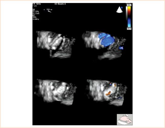
FIGURE 13.6 Doppler color flow full-volume 3D TEE transgastric aortic valve long-axis view at a multiplane angle of 155 degrees of a normally functioning mechanical bileaflet valve in the aortic position viewed from the left ventricular side in systole with the occluders open (top panels) and in diastole with the occluders closed (bottom panels). Color suppression (left panels) demonstrates the position of the occluders in the open (top left panel) and closed positions (bottom left panel). Doppler color flow imaging (right panels) demonstrates the normal pattern of transvalvular flow through the three orifices of the prosthetic valve during systole (top right panel) and normal pattern of regurgitant jets at the hinge points of the occluders during diastole (bottom right panel). Small transvalvular regurgitant jets can often be detected between the occluder and the annular stent in a normally functioning mechanical bileaflet prosthetic valve (not shown) (Courtesy of Drs. Cheung and Streckenbach).
2. Confirm proper valve seating: Incomplete fixation of the prosthetic sewing ring to the native annulus or dehiscence of the sewing ring will cause paravalvular regurgitation. Paravalvular regurgitation is defined as regurgitation originating outside of the prosthetic valve annulus or sewing ring (Fig. 13.7, Video 13.3). The most common cause for incomplete fixation immediately after prosthetic implantation is a severely calcified native valve annulus or an avulsed annular suture. Prosthetic endocarditis is the most common cause for late valve dehiscence and can produce a “rocking” motion of the entire valve apparatus on 2D imaging. Proper seating of the prosthetic valve, paravalvular regurgitation, and dehiscence are best identified from the multiplane long-axis images of the valve.
3. Confirm normal blood flow patterns and the absence of pathologic transvalvular and paravalvular regurgitation: Color flow Doppler imaging will demonstrate central antegrade flow through the valve annulus when the leaflets open and small characteristic regurgitant jets during leaflet closure. A small amount of regurgitation is normal for bileaflet prosthetic valves and is caused by closure backflow and leakage backflow. Closure backflow is the reversal of flow required for closure of the leaflets. Leakage backflow occurs after closure of mechanical valves, originates from the four hinge points of the leaflets and at other locations between the edges of the occluder and the prosthetic valve stent. The leakage backflow jets originating from the hinge points produces four centrally directed regurgitant jets that are best visualized in the long-axis image through the prosthetic valve at a multiplane angle aligned parallel to the leaflets (Figs. 13.1, 13.5, 13.6, Videos 13.2, 13.4, and 13.5). These washing jets originate laterally near the inner border of the prosthetic annulus and are directed medially into the left atrium. The bileaflet valves are designed to permit a small amount of regurgitation at the hinge points to prevent the formation of thrombus within the hinge mechanism. Sometimes, small leakage regurgitant jets originating along the edge of the leaflet where it meets the annulus during closure can also be imaged by color Doppler imaging (Fig. 13.5). Normal physiologic regurgitant jets are small and short in duration and can be distinguished from pathologic transvalvular regurgitation based on their size, location, direction, and duration.
Pathologic regurgitation with a jet originating within the sewing ring is called transvalvular regurgitation. Pathologic transvalvular regurgitation immediately after valve implantation indicates malfunctioning of the valve leaflets. Intraoperative causes of leaflet malfunction causing transvalvular regurgitation include retained tissue preventing valve closure, a misplaced suture interfering with leaflet motion, or debris within the hinges causing trapping of the leaflet in a fixed position (Fig. 13.8). Significant regurgitant jets originating outside of the sewing ring are always pathologic and called paravalvular regurgitation.
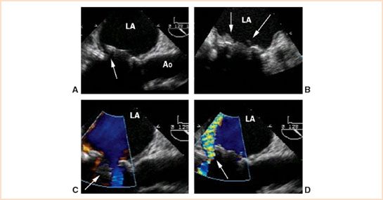
FIGURE 13.7 Transesophageal midesophageal long-axis view in a patient with a caged-ball prosthesis in the mitral position complicated by prosthetic valve endocarditis and dehiscence. Two-dimensional imaging (panel A) demonstrated a rocking motion of the prosthetic valve and separation of the sewing ring from the native annulus in the region of the posterior mitral valve annulus (arrow, panel A) that was characteristic of dehiscence. Vegetations on the prosthetic valve that were diagnostic for endocarditis were detected also by 2D imaging (arrows, panel B). Doppler color flow imaging in diastole showed antegrade flow around the open occluder into the left ventricle (arrow, panel C). Doppler color flow imaging in systole demonstrated paravalvular regurgitation in the region of dehiscence (arrow, panel D) (Courtesy of Drs. Cheung and Streckenbach). LA, left atrium; Ao, aorta.
4. Calculate valve gradient and effective orifice area: The hemodynamic performance of the prosthetic valve can be assessed using Doppler echocardiography (Fig. 13.9). The interpretation of Doppler-derived prosthetic valve hemodynamic parameters is complicated because even normally functioning prosthetic valves are inherently obstructive to blood flow, and blood flow velocity profiles across prosthetic valves are not uniform depending upon prosthetic valve type, model, and annular diameter. Since the blood flow velocity through the central rectangular orifice is greater than the blood flow velocity through the two semicircular orifices of the bileaflet valves, some studies suggest that Doppler-derived gradients based on the Bernoulli equation may overestimate the true transvalvular gradient (11). Yet the same and other studies suggest also that differences observed between Doppler- and catheter-derived gradients across prosthetic valves can be explained by localized gradients and pressure recovery downstream from the valve orifice (11,12). Based on this interpretation, differences between Doppler- and catheter-derived pressure gradients may not represent an overestimation of catheter-derived gradients, but represent instead inherent differences in measurement technique, line of interrogation, and precise location of pressure gradients relative to the prosthetic valve orifices. Furthermore, the equation used to estimate mitral valve area based on pressure half-time (MVA = 220/PT1/2) may not apply to prosthetic valves that differ in structure and flow characteristics to the native valve. For clinical purposes of quantifying prosthetic valve function, several approaches can be applied for interpretation of Doppler-derived measurements. One approach is to report only actual values of Doppler transvalvular peak and mean flow velocities across the prosthetic valve and compare the values to established normal values for the specific type, model, and size of the prosthetic valve based on clinical reports, specifications published by the manufacturers that can be obtained from their respective websites or the package insert accompanying the prosthetic valve (9), or in the appendix of the American Society of Echocardiography guidelines for the evaluation of prosthetic valves (Appendix D) (1,10). Similarly, Doppler-derived effective orifice areas calculated using the continuity equation for a prosthetic valve can be compared to those observed for that specific prosthetic valve type, model, and size (Table 13.3 and Appendix D) (1,10). Another variable adding to the complication of interpreting Doppler-derived hemodynamic information in patients with prosthetic valves is that Doppler-derived pressure gradients are dependent on blood flow and even blood viscosity. Decreased blood viscosity from hemodilution or increased cardiac output from inotropic support immediately after prosthetic valve implantation may lead to overestimation of prosthetic valve gradients using the simplified Bernoulli equation. One approach to address this problem of assessing aortic valve prosthetics is to index transvalvular Doppler blood flow velocity through the prosthetic valve to the blood flow velocity through the LVOT using the Doppler velocity index (DVI = VLVOT/VAoV) (Table 13.4) (1,13,14). For example, using the DVI or the “double envelope” technique for assessing the function of a prosthetic valve in the aortic position, a peak blood flow velocity in the LVOT (VLVOT) to peak transvalvular blood flow velocity (VAoV) ratio less than 0.25 (VLVOT/VAoV < 0.25) suggests significant prosthetic valve stenosis (Table 13.5) (1,13). Another approach is to estimate prosthetic valve gradients using the nonsimplified Bernoulli equation that accounts for the velocity of blood flow on the upstream side of the valve ([P1 − P2] = 4[V22 − V12]). Similarly, for assessing the function of a prosthetic valve in the mitral position, a transvalvular velocity–time integral (VTIMV) to LVOT velocity–time integral (VTILVOT) ratio greater than 2.5 (VTIMV/VTILVOT > 2.5) suggests significant prosthetic valve stenosis (Tables 13.4 and 13.6) (14).
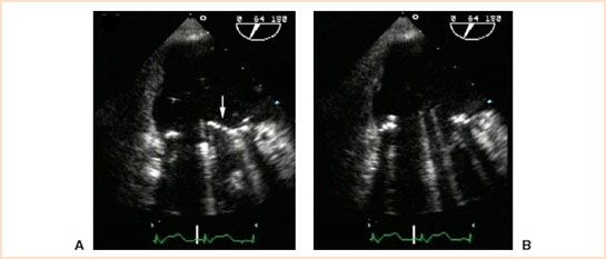
FIGURE 13.8 Intraoperative TEE midesophageal commissural view at a multiplane angle of 64 degrees displaying a mechanical bileaflet prosthetic in the mitral position. TEE imaging of the bileaflet view in diastole immediately after implantation demonstrated that the anterior leaflet was trapped in a closed position (arrow, panel A). TEE examination after surgical revision to free trapped leaflet showed that both leaflets were fully open in diastole (panel B) and moved normally throughout the cardiac cycle.
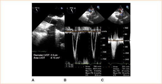
FIGURE 13.9 The functional performance of prosthetic valves implanted in the aortic position can be assessed by TEE in mid-systole by using 2D imaging to measure the diameter of the left ventricular outflow tract in the midesophageal aortic valve long-axis view (panel A), pulsed wave Doppler to measure the blood flow velocity in the left ventricular outflow tract in the transgastric aortic valve long-axis view (panel B), and continuous wave Doppler to measure the transvalvular blood flow velocity in the transgastric aortic valve long-axis view (panel C). In this example of a 29-mm bioprosthetic valve implanted in the aortic position, the transvalvular peak gradient was 21 mm Hg and mean gradient was 10 mm Hg using the simplified Bernoulli equation. Using the nonsimplified Bernoulli equation, the transvalvular peak gradient was 12 mm Hg and mean gradient was 6 mm Hg. The Doppler velocity index (DVI) was 0.66, and the effective orifice area was 2.4 cm2 (Courtesy of Drs. Cheung and Streckenbach).
TABLE 13.3 Determining the Effective Orifice Area (EOA) Using the Continuity Method
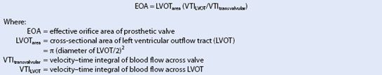
TABLE 13.4 Determining the Doppler Velocity Index (DVI)
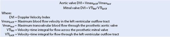
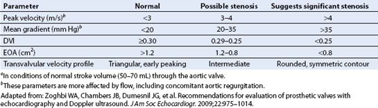
TABLE 13.5 Doppler Parameters for Diagnosis of Prosthetic Aortic Stenosisa
Caged Ball
Caged-ball valves were the first prosthetic valves implanted in humans. They consist of a silastic or metal ball occluder housed in a wire cage with three or four struts. The ball occluder casts a large acoustic shadow and its motion within the cage is best imaged in the long-axis plane of the valve (Fig. 13.10). In the short-axis imaging plane, the ball occluder can be imaged within the wire struts. Doppler color flow imaging in the short-axis plane of the valve demonstrates blood flow between the wire struts through the outside perimeter of the ball occluder (Fig. 13.10).
Tilting Disc
Tilting disc valves have been utilized in the aortic, mitral, and tricuspid positions. They consist of a single-disc occluder supported by struts. The single-disc occluder pivots open 60 to 80 degrees to form two orifices of different size and shape. They have a low profile and offer the advantage of providing a large orifice size in relation to its stent size. Although tilting disc valves are no longer in production for implantation in the United States, there are still many patients with these mechanical valves in the population. The two primary models of tilting disc valves can be distinguished by the presence of a central aperture in the Medtronic Hall and the absence of a central aperture in the Bjork Shiley valve when examined by color Doppler imaging (Figs. 13.11 and Figs. 13.12).
Echocardiographic examination includes the following:
1. Confirm proper tilting action of the occluder in the long-axis imaging plane.
2. In the short-axis imaging plane, one edge of the disc occluder should move in and out of the imaging plane as the valve tilts open.
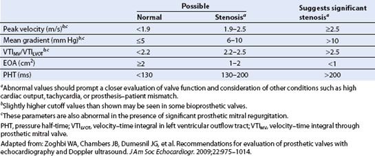
TABLE 13.6 Doppler Parameters for Diagnosis of Prosthetic Mitral Stenosis
Related posts:
 A Practical Approach to the Echocardiographic Evaluation of Ventricular Diastolic Function
Stay updated, free articles. Join our Telegram channel

Full access? Get Clinical Tree


