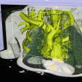
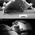
Fig. 53.1
Three hybrid X-ray/MRI (XMR) system concepts. (a) First-generation XMR system. (b) Truly hybrid XMR system. (c) Closed-bore (CBXMR) system
XMR System Requirements
Table 53.1 lists the X-ray system requirements for the guidance of PAVR and CTO procedures. The requirement for a rotating anode X-ray tube originates from the long fluoroscopy times and the use of a higher exposure rate record mode, formerly known as “cine,” which provides images of archival quality with a higher signal-to-noise ratio than fluoroscopic acquisitions. Fluoroscopic X-ray times for PAVR and CTO procedures are on the order of 20 and 50 min, respectively. Currently available stationary anode X-ray tube designs could provide the desired long fluoroscopic X-ray exposures without overheating if the anode is water-cooled. However, visualization of small guidewires and low-contrast as well as poorly opacified arteries requires the higher X-ray fluorescence cine mode that can only be achieved with a rotating anode design to reduce X-ray focal spot loading.
Table 53.1
Imaging requirements for percutaneous aortic valve replacement (PAVR) and chronic total occlusion (CTO) recanalization
Requirement | Value | Reason |
|---|---|---|
Oblique C-arm angulation | ~40°left/right anterior oblique | Angulation needed for adequate visualization of the proximal coronary arteries, aortic annulus and aortic root |
Minimum frame rate | ≈10 frames/s | Real-time imaging required to position and deploy the bioprosthesis |
Minimum spatial resolution | 1 line pair/mm | Need to resolve a 0.035″ guidewire relative to its surroundings |
Source-to-image distance | 85–120 cm | Adequate room for the patient and tabletop, proper entrance exposure levels to the patient |
Maximum X-ray tube current | Several hundred mA | Large tube current required for X-ray record mode, heat dissipation for extended fluoro acquisition |
X-ray tube kilovoltage | 50–125 kV | Adequate kV range for proper image contrast of full range of patient body types |
Minimum field of view size | 18 × 18 cm | Adequate visualization of the ascending aorta, cardiac chambers and the apex during a PAVR procedure. Visualization of CTO as well as distal vessel segment |
Field of view alignment accuracy | Within 2 % of the source-to-image distance | Food and drug administration regulation to minimize unnecessary exposure to the patient and the staff |
The requirements for patient access during percutaneous procedures are less stringent than for surgery, whereby the physician is working directly above the treatment area. The entry sites for cardiac percutaneous procedures are the radial and femoral arteries. PAVR procedures always involve a femoral puncture due to the large size of the prosthetic valve, whereas angiography and PCI use both access routes. The entry sites remain accessible even during MR imaging, if a closed short-bore superconducting magnet is used with the patient resting in the head-first orientation inside the scanner. Closed-bore superconducting magnet designs achieve higher magnetic fields (B0), providing greater signal-to-noise ratio images that are desirable in order to assess the rapidly moving cardiac anatomy.
Closed-Bore XMR System
Bracken et al. [55–57] have performed simulations and experiments to determine the effects of B0 on all potentially vulnerable components of the proposed closed-bore XMR system design proposed by Brzozowski et al. [54]. The system consists of a 1.5 GEHC cardiac MRI system and a rotating anode X-ray catheterization system that can be operated in the fringe field near the MRI-bore entrance. This design, depicted in Fig. 53.1c, allows rapid patient transfer from one imaging modality to the other due to the short distance of the cone-beam X-ray irradiation field from the magnet. This distance is sufficiently small that devices connected to the patient via wires or tubing can be easily accommodated with little more than 1 m of slack in said connections.
An X-ray tube located 140 cm from the bore entrance would be subject to a field of 5 mT, according to Fig. 53.2. For the largest cranial angulation of 40°, the X-ray detector is ~120 cm from the bore entrance and the field is 10 mT. For the largest caudal angulation, the flat-panel detector is ~120 cm from the bore entrance. Bracken et al. have found that some X-ray system components are affected by B0 but not to a degree that significantly affects imaging performance.
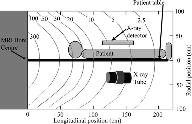
Fig. 53.2
Fringe field in mT near the MRI bore
The first effect of B0 on the X-ray tube is a reduction in the anode rotation frequency shown in Fig. 53.3a due to the field component perpendicular to the anode axis of rotation. The magnetic field gives rise to a braking force which slows the anode and causes a small increase in the heat deposited in the anode. The electronic beam dwell time on the rotating anode is increased due to the lower anode rotation frequency, causing a small reduction in the maximum tube current that can be applied without damaging the anode surface. This effect is small even for the maximum cranial angle. The second effect relates to changes in the electron beam traveling from the cathode to the anode. Electrons experience a force in the presence of the magnetic field causing bending of the electron beam and a change in the beam profile arriving at the anode. Figure 53.3b shows the shift in the X-ray focal spot as the strength of the field increases. These images were obtained by imaging a 100 μm Tantalum pinhole located at the output port of the X-ray tube. The image scale is referred to the anode by correcting for the ten times magnification of the focal spot. A shift in the focal spot of 1 mm will cause the X-ray image of a feature in a patient positioned halfway between the X-ray source and detector to also shift by 1 mm. The focal spot shift also causes the edge of the radiation field to shift, such that operating the system at the maximum field of view (as determined by the dimensions of the detector) could potentially result in irradiation beyond the detector edge. According to FDA regulations, radiation must not go beyond these edges by more than 2 % of the source detector distance, in order to prevent irradiation of the patient with X-rays that do not contribute to the image. Making the field of view smaller than the dimensions of the detector easily fulfills this requirement. The focal spot shift varies with C-arm orientation, but this is irrelevant in most clinical scenarios, with the exception of cone-beam reconstruction, where shift corrections are required in order to maintain the reconstructed image resolution.
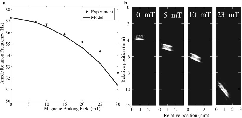
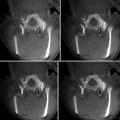
Fig. 53.3
Effect of B0 on X-ray tube operation. (a) Reduction in anode rotation frequency as a function of the magnetic field. (b) X-ray focal spot position for different magnetic field values. Bending of the electron beam causes the focal spot position to shift as the B0 is increased. The shift is small enough that the focal spot remains on the beveled part of the rotating anode. The focal spot intensity distribution expands for the higher 23 mT value
Figure 53.3b also shows how the pattern of energy deposition in the anode is altered. There is a noticeable expansion of the X-ray source as the field increases to 23 mT, which is a higher value than the tube would experience for high cranial angles. Expansion of the focal spot increases blurring of the X-ray image.
If the system is operated with a 3 T or 7 T magnet, some shielding of the magnetic field may be required. We have determined that a Helmholtz coils pair can reduce the magnetic field experienced by the X-ray tube [55].
The effect of the magnetic field on the flat-panel detector was also investigated. An Anrad (Montréal, QC, Canada) direct conversion selenium flat-panel detector was placed on the MRI patient table at a distance of 120 cm from the magnet-bore entrance and activated. All the electronic components functioned normally. The only modification to the panel was the replacement of the aluminum cooling fan blades, which are prone to eddy currents, with plastic equivalents. Final tests with X-rays could only be completed upon installation of the C-arm in the MRI and revealed no noticeable image degradation. X-rays interacting with the radiation-sensitive selenium layer produce electron-hole pairs which travel for a short distance of 100 μm under a large electric field of 30 kV/mm, so that the effect of the magnetic field on electron and hole motion is negligible.
Figures 53.4 and 53.5 illustrate the completed CBXMR prototype developed at Sunnybrook Health Sciences Centre, Toronto, Canada. The MRI system is a 1.5 T General Electric Healthcare (GEHC, Milwaukee, WI, USA) Signa Excite HDx, while the room housing these systems is both radio frequency and X-ray shielded. The system is made of components purchased from OEMs, as well as parts designed and machined in house, with the exception of larger pieces such as the C-arm floor base and pedestal which required machine work on a larger scale than could be accommodated at our institution. The C-arm armature (Omega Medical Imaging, Sanford, FL) is made of aluminum. The C-arm pedestal column, which experiences high mechanical forces, is made of non-ferromagnetic stainless steel. The pedestal base was secured into the concrete floor via four bolts, which are in contact with the copper sheet which is part of the radio frequency shielding, thereby grounding the X-ray system to the faraday cage. Aluminum (Al) was otherwise used wherever possible, in order to replace larger steel components reducing magnetic forces due to the fringe field and maintaining field homogeneity within the bore, an important determinant of MRI image quality. A custom X-ray- and MRI-compatible table was also constructed. The table docking mechanism was adapted from a design developed by Sentinelle Medical (Toronto, ON, Canada). The table section exposed to X-rays was made of foam core covered with a thin layer of medium-density fiber board (MDFB, a mixture of wood and resin), minimizing X-ray absorption and surfaced with epoxy. Other sections of the table were made using 2.5 cm thick MDFB coated with epoxy. A frame made of extruded aluminum beams supports the patient table. There is an absence of supports below the table over a distance of 100 cm, allowing the X-ray tube to move freely under the patient. Cranial and caudal angulations up to ~40° are possible.
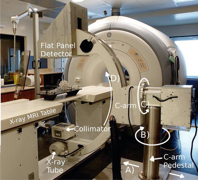
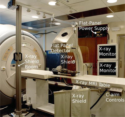
Fig. 53.4
An image of the CBXMR system installed at Sunnybrook Health Science Centre showing the C-arm pedestal and C-arm which supports the X-ray tube, collimator, and flat-panel detector. The direction of motorized lateral motion of the C-arm pedestal is highlighted in A Rotation about B by approximately 90° is done to park the C-arm out of the way when only the MRI is used. Rotations about C and D which are motorized are performed to obtain the desired view angulations during image acquisition
Fig. 53.5
An image of the CBXMR system showing the custom-built dockable X-ray table, MRI-compatible X-ray monitors, mobile X-ray shield boom, and the flat-panel detector. C-arm controls are used to move the C-arm laterally as shown in Fig. 53.4
Figure 53.4 shows the C-arm pedestal. In the current design, the base of the C-arm protrudes above the floor on one side of the table, creating a tripping hazard, and thus patients are invited to sit on the table on the opposite side. The base of the C-arm could have been imbedded into the floor if the XMR system design had been completed before MRI suite construction. The base securing the C-arm pedestal moves laterally to the magnet bore as indicated by the arrow shown in (A). Motion along (A) is controlled by a worm drive and facilitated by an electric motor. Rotation about (B) is achieved manually and is meant to rotate the C-arm ~90° from the table and out of the way when it is not in use. Rotations depicted in (C) and (D) are also facilitated with motors allowing the physician to easily obtain images from a wide range of angulations. The direct current motors used in this setup required no modifications.
The motors are controlled via switches found at the side of the table, as shown in Fig. 53.5. Rotation about (D) is achieved with non-ferromagnetic stainless steel bearing and races. Rotations about (B) and (C) are achieved with rubber bearings contained in Al races. A mobile aluminum boom (Fig. 53.5) was built to support a leaded glass shield that can be positioned to protect the physician during interventions. Figure 53.5 also shows an X-ray shielding curtain at the side of the table. The C-arm swings away from the magnet and the patient table, allowing access to the patient from both sides of the table.
The X-ray system was developed to acquire images for a variety of interventional vascular imaging applications. In fluoroscopy mode, the system acquires images at 15 and 30 frames/s. The fluoroscopy technique parameters are controlled by an automatic exposure control (AEC) feedback algorithm where the kV and mA vary depending on patient attenuation. The fluoroscopic tube voltage ranges from 50 to 125 kV, and the tube’s current and X-ray pulse time vary but are limited, such that the maximum fluoroscopic patient entrance exposure is less than 5 R/min. In the serial radiographic mode of operation, the X-ray system may acquire images at rates of 1–15 frames/s. This range in frame rate allows the X-ray system to be used for general vascular X-ray procedures at low to moderate frame rates (up to 7.5 frames/s) and for cardiovascular X-ray imaging procedures at frame rates of 15 frames/s. In higher exposure rate serial radiographic mode of operation, the kV varies between 50 and 125 kV, and the mAs are controlled by an AEC device (Advanced Instruments Development) that is used to terminate the X-ray pulse when the X-ray exposure reaches a certain level (10–20 microR/frame) at the entrance of the flat-panel detector. Ferrous materials were removed from the AEC ionization chamber frame. The X-ray collimator (Huestis Medical, Bristol, RI, USA) provides X-ray filtration equivalent to 2 mm of Al and was modified by removing some ferrous components. The X-ray tube used in the system is a standard Varian (Salt Lake City, Utah, USA) A292 rotating anode X-ray tube.
In order to maintain the signal-to-noise ratio of the MR images, extensive shielding strategies were employed to prevent the introduction of radio frequency (RF) noise. The X-ray system is not operated during MRI acquisition because the fields of view of both imaging systems do not overlap. However, the X-ray generator is powered and ready to produce X-rays while the flat panel is in standby mode ready for image acquisition. In this mode, the X-ray system generates no significant RF noise. A CPI (Georgetown, ON, Canada) Indigo 100 SP 100 kW X-ray generator is located in the MRI equipment room. The generator and all cables to the isolation panel were carefully shielded and grounded. Video data from the flat-panel detector is transmitted via fiber optic and crosses the isolation panel to a computer, where spatial and temporal image processing is performed. The processed images travel back to the MRI via fiber optic to shielded MRI-compatible LCD monitors. Differences in the performance of our system, as compared to a state of the art catheterization system, such as in the generator power rating and X-ray tube heat capacity, are reflections of budget limitations and not fundamental limitations caused by the MRI environment.
Related posts:

Stay updated, free articles. Join our Telegram channel

Full access? Get Clinical Tree


