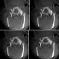
Fig. 42.1
Screen shot of integrated navigation and MRI thermometry software, 3D Slicer, with an ability to perform preoperative image registration to intraoperative MRI (Jolesz FA, Bleier AR, Jakab P, Ruenzel PW, Huttl K, Jako GJ. MR imaging of laser-tissue interactions. Radiology. 1988;168(1):249–53)
Graphical Presentation. We prepared graphical representations of tools specific to MRI LITT, including fiducial points with arbitrarily changeable diameter and a locator that represents the tracking wand to guide the laser fiber. The fiducials, representing anatomical landmarks and the target lesion, can be stored as a uniquely named list. In addition to mouse-controlled slice selection, the 3D Slicer provides slice selection using the locator, i.e., digital wand, for fiber placement; this is the most common use of a digital wand in navigation software during surgery. A relatively simple TCP/IP-based client/server communication package was developed to receive the coordinates of the digital wands online.
Registration. Native image-to-image registration in 3D Slicer was extended to fuse a preoperative information-rich image to an intraoperative image or to fuse a sequence of intraoperative images. The methods include manual rigid registration using slider bars in a graphical user interface and automatic rigid registration based on maximization of mutual information [29].
MRI Thermometry. MRI can provide a thermal map for ablation therapy and monitor the extent of heat perfusion during microwave or laser-ablation therapy [14, 18, 27]. This MRI thermometry is useful to control the ablation therapy, maximize the coverage of an ablation lesion, and lessen damage to surrounding critical tissue [26]. Using a sequence of fast 2D spoiled gradient-recalled sequences, 3D Slicer computed the phase differential computation. The magnitude, phase, real, and imaginary images can be transferred online in real time from the MRI scanner to the 3D Slicer workstation and presented to the physicians. The detail of the imaging sequence is discussed later.
Clinical Trial
Fourteen patients were treated as part of a prospective study. Extended follow-up on the subjects were enrolled throughout the 10-year period between August 1996 and August 2006. Inclusion criteria were that subjects were adults (with the exception of one child) with inoperable or surgically difficult-to-access tumors due to their proximity to eloquent areas and no contraindications for being scanned in an MRI environment. Tumor types included astrocytoma (n = 4), glioblastoma (n = 4), oligodendroglioma (n = 1), metastasis (n = 2), pilocytic astrocytoma (n = 2), and high-grade gliosarcoma (n = 1).
All subjects underwent preoperative MRI examinations including multiplanar T2-weighted fast spin echo (FSE) images, T1-weighted spin echo (SE) images, and dynamic T1-weighted images after intravenous administration of 20 cc of gadolinium contrast (Magnevist, Berlex, Wayne, NJ). Prior to the LITT, two radiologists interpreted these MR studies. MR image-based targets were defined as focal areas of (1) high signal intensity in T2-weighted images or (2) abnormal increased enhancement in post-gadolinium dynamic images.
Intraoperative Imaging
Laser ablation took place in a surgical procedure room equipped with an interventional MRI scanner (0.5 T Signa SP, GE Healthcare Technologies, Waukesha, Wisconsin) [22]. Anesthesia was delivered as either general inhalation anesthesia or as intravenous sedation.
Intraoperative 0.5 T contrast-enhanced T1 images were obtained prior to fiber insertion. The fiber insertion path was planned on-site. Phase computation, or MRI thermometry, from real and imaginary components of SPGR sequences was performed using the method described by Kuroda et al. [14]. In the cases after March 2005, these intraoperative images were registered with preoperative 1.5 T images using 3D Slicer to facilitate integrated visualization of the entire array of patient image sequences. Registration was performed using a rigid registration technique based on maximization of mutual information [29]. Integrated views of the registered intraoperative 0.5 T and preoperative 1.5 T images were analyzed by a radiologist who specified the locations of tumor sites. Fibers were placed under intraoperative MRI guidance as well as fused images in 3D Slicer aiming at an optimal placement of the fiber tip to maximize the ablation of the tumor.
Laser Deposition and Monitoring
A continuous wave Nd:YAG laser (PhotoMedex, Montgomeryville, PA) operating in the near infrared at 1,064 nm was used for treatments. Light was delivered through the end of a bare 0.6 mm optical fiber in patients #1–#9, or through a 1 or 2 cm diffusing fiber in patients #10–#16. Bare fibers were placed directly into tissue; diffusing fibers were sheathed in non-cooled catheters.
The tissue around the fiber tip was heated by the absorbed laser light. The targeted tumor volume was treated with a temperature above 60 C, causing a thermal coagulation of the proteins of the cell. We tried to go above the threshold for protein denaturation but below 100° to avoid boiling the tissue water that can then cause damage by producing bubbles that substantially damage far away from the tip of laser the fiber. In most cases the heated volume was 3–4 cm in diameter at 6 W. The whole intervention was controlled by MRI thermometry, and right after that, a control MRI was administered to check the absence of any bleeding. Total laser output powers ranged between 1 and 6 W. Deposition of the heat for 3 min was repeated, until the MRI thermometry confirmed the extent of heated lesion covers the MRI-enhanced tumor lesion. For the follow-up, a 24-h, 1-month, and 3-month MRI examinations were made in most cases.
The summary of age, location of tumor, treatment and diagnosis history, and the pathological outcome preceding the LITT treatment is presented in Table 42.1. All patients underwent 1 case of MRI-guided LITT. In all 14 cases, no complications were reported. In 2 cases out of 14, the subjects had a subsequent craniotomy after LITT because of the recurrence of the tumor in or near the treatment site of LITT at 4, 5, and 80 months after the LITT. Nine patients underwent radiation therapy (50–104.4 Gy with stereotactic boost), and 9 obtained multiple chemotherapy treatments. Intraoperative data with the number of deposition sites, power wattages and durations of deposition per site, and repetitions of deposition at a site if any is presented in Table 42.2.
Table 42.1
Subject
Subject # | Location | Pathology | Treatment history | Age at LITT | |
|---|---|---|---|---|---|
1 | Left | Frontal, parietal, temporal | Glioma | None | 35 |
2 | Left | Thalamic | Anaplastic astrocytoma | None | 37 |
3 | Left | Frontal | Glioma | Craniotomy (−2 mo., glioma) | 76 |
4 | Left | Thalamic | Astrocytoma | 46 | |
5 | Left | Frontal | Glioma | Craniotomy (−19 mo., glioma) | 34 |
6 | Midline | Thalamic | Astrocytoma | 7 | |
7 | Right | Frontal | Glioma | Craniotomy (−50 mo. astrocytoma) | 50 |
8 | Midline | Posterior fossa | N/A | Craniotomy (−18 mo. reactive changes) | 78 |
9 | Left | Occipital | Pilocytic astrocytoma | 36 | |
10 | Midline | Brain stem/thalamic | Multiforme glioblastoma | 22 | |
11 | Left | Frontal | Glioma | Craniotomy (−4 mo. glioma) | 47 |
12 | Left | Parietal | Reactive changes | 23 | |
13 | Right | Frontal | Multiforme glioblastoma | 55 | |
14 | Multiplex | Multiple | Glioma | Craniotomy (−43 mo., anaplastic astrocytoma; −102 mo. oligodendroglioma) | 48 |
Table 42.2
Laser parameters
Subject # | ||
|---|---|---|
1 | Site 1: | Bare fiber |
3 W 60 s + 3 W 60 s + 3 W 60 s + 3 W 60 s + 4 W 60 s | ||
2 | Site 1: | Bare fiber |
3 W 60 s + 3 W 60 s + 3 W 60 s | ||
Site 2: | ||
3 W 60 s + 3 W 60 s | ||
3 | Site 1: | Bare fiber |
4 W 60 s + 4 W 60 s + 4 W 60 s | ||
Site 2: | ||
4 W 60 s + 4 W 60 s + 4 W 60 s | ||
4 | Site 1: | Bare fiber |
2 W 60 s | ||
Site 2: | ||
2 W 60 s | ||
Site 3: | ||
2 W 480 s | ||
5 | Site 1: | Bare fiber |
2 W 288 s | ||
6 | Site 1: | Bare fiber |
2.5 W 300 s + 3.5 W 300 s
Stay updated, free articles. Join our Telegram channel
Full access? Get Clinical Tree
 Get Clinical Tree app for offline access

|
