MRI of Spinal Trauma
Adam E. Flanders
Eric D. Schwartz
Sidney E. Croul
Introduction
Prior to the development of magnetic resonance imaging (MRI), the extent of associated soft tissue injury to the intervertebral discs, ligaments, and spinal cord was determined primarily by inference from known biomechanical principles rather than by direct imaging of the affected tissues (1,2). Consequently, many of the established therapies for spinal cord injuries (SCIs) are based on radiologic classifications of osseous injury to the spinal column. These traditional therapeutic interventions for SCI are directed primarily by radiographic findings such as re-establishment of normal anatomic alignment of the spinal canal and removal of bone fragments. Current management of SCI, however, has become more directed toward correction of the associated soft tissue and spinal cord damage (3,4,5,6), and MRI has become increasingly important in the diagnostic evaluation of spinal injuries.
The greatest impact that MRI has made in the evaluation of SCI has been in assessment of the intracanalicular and paraspinal soft tissues (3,4,6,7,8,9,10,11,12,13,14). The integrity of the intervertebral discs and ligamentous complexes can be routinely evaluated with MRI. In addition, MRI permits direct visualization of the morphology of the injured cord parenchyma and the relationship of the surrounding structures to the spinal cord (2,15). No other imaging modality has been able to faithfully reproduce the internal architecture of the spinal cord and it is this particular utility of MRI that promises to have the greatest impact on the management of the SCI patient in the future.
Although MRI is a powerful diagnostic tool, it is not a replacement for modalities that assess bony integrity (15). Radiography is utilized far less often in the initial assessment of spine trauma. Multi-detector CT (MDCT) with sagittal and coronal reformatted images is the mainstay for assessment of osseous injury in adults. Radiography is still reserved for the pediatric population because of radiation dose considerations (8,9,15,16,17). MRI is the primary imaging option available to assess for residual soft tissue compression of the spinal cord (7,12,18,19,20) due to factors such as acute disc herniations and epidural hematomas. Identification of residual compression of the spinal cord has significant implications in regard to timing of subsequent surgery and the type of surgical approach that is required (7,9,19). MRI is also an essential diagnostic modality in cases of SCI without radiographic abnormality (SCIWORA) (14,16,19,21,22,23,24,25). An MRI examination in the acute period is warranted in any patient who has a persistent neurologic deficit after spinal trauma (12,14,16).
The focus of this chapter is the application of MRI in the evaluation of injuries of the spinal axis and spinal cord.
Demographics of Spinal Cord Injury
SCI is a significant cause of disability in the United States. Although the number of individuals who sustain paralysis yearly is substantially less than the number of people who sustain moderate to severe traumatic brain injury (TBI) (11,000 SCI per year versus 70,000 to 90,000 TBI per year), the financial costs to society for SCI are significant. Since most patients survive the acute SCI, there are approximately 225,000 to 288,000 SCI patients with partial or complete paralysis currently being cared for in the United States. The total lifetime costs for medical treatment and rehabilitation range from $200,000 to $800,000 per individual. The lifetime direct costs may exceed $2.8 million, for a high tetraplegic patient inured at age 25 (26,27). Nearly 55% of all SCI occur in young adults between the ages of 16 and 30 years, although the most recent statistics suggest that the average SCI patient is much older than previously reported likely due to the larger proportions of SCIs from falls in the elderly population. The overall incidence of cervical spine injury from a multi-institutional survey of 615 US trauma centers was estimated to be 4.3%. The incidence of cervical spine injury without SCI was 3.0% and the incidence of cervical SCI without fracture was 0.7% (28). Most SCI victims are white males (81.7%). The etiologies of SCI are vehicular (37.4%), acts of violence (25.9%), falls (21.5%), and sports injuries (7.1%) (26). Since SCI primarily affects employed (60.5%) young adults, there is a tremendous financial loss to society in terms of overall lifetime productivity.
Injuries to the spinal axis can be subdivided into spinal injuries (damage to the spinal axis without neurologic injury) and SCI (damage to the spinal cord with or without spinal axis abnormality). An accurate estimate of the total number of SCI is difficult to define because patients who expire in the field from a fatal SCI (i.e., high cervical cord) or from related injuries (e.g., cerebral trauma) are not included in the national statistics. Tetraplegia (quadriplegia) is defined as an injury to one of the eight cervical segments of the spinal cord with paralysis of all four limbs. Paraplegia usually results from injury to the thoracic, lumbar, or sacral segments of the spinal cord with dysfunction of both legs. A neurologically complete lesion is one in which there is no motor or sensory function three segments below the neurologic level of injury (NLI) and no sparing of sacral sensation. Of those spinal cord–injured persons who survive to reach a medical facility, the most frequent neurologic deficit is incomplete tetraplegia (29.5%), followed by complete paraplegia (27.9%), incomplete paraplegia (21.3%) and complete tetraplegia (18.5%) (26). Less than 1% of SCI patients recover completely during the initial hospitalization.
MRI Techniques
Imaging Considerations
The spinal cord–injured patient requires special consideration before MRI with regard to patient transfer, life support, monitoring of vital signs, fixation devices, choices of surface coils, and pulse sequences. The potential risks from transporting a medically and neurologically unstable patient must be carefully weighed against the potential benefits derived from the diagnostic information provided by MRI. There are known inherent risks associated with removing a patient from an intensive care environment, transporting them to the MRI suite and allowing them to remain recumbent in the MRI unit for a prolonged period of time (29,30). There is an increased risk of secondary brain injury from hypoxia, aspiration, and vascular events by removing an unstable patient from the ICU environment.
Patients with cervical spine injuries are usually stabilized with a fiberglass or foam cervical collar or, in more severe injuries, a halo and halo vest are used (31). For thoracic and lumbar injuries, the patient may be transported on a rigid spine board, a body cast, or occasionally in traction. MRI-compatible halo vests are often composed of a graphite composite, titanium, aluminum, and plastic, and are devoid of stainless steel components (32,33). If the fixation pins used for femoral traction are ferrous, they usually do not interfere to any noticeable degree with the images of the spine, although tissue heating can occur at the contact points with skin.
Patient motion (voluntary or involuntary) can also be detrimental to the quality of any MRI study. Even a patient with acute tetraplegia can seriously degrade a cervical MRI examination either by movement of the head and neck or from irregular ventilation. Sedation may be necessary to complete an examination.
Choice of surface coil is determined by the location(s) of injury, access to the area of interest, and the types of coils available. The proximity of the surface coil to the area of interest is a key factor in determining image quality. Temporary removal of a cervical collar, for example, will permit the use of specially designed quadrature or anterior/posterior neck coils. Wherever possible, a dedicated spine phased-array coil system should be used to maximize coverage and optimize MRI signal. Integrated head and neck phased-array systems work well and will produce quality vascular imaging. When the neck is fixed in a halo vest (Fig. 22.1), the use of a phased-array coil system can be problematic as the distance between the coil surface is increased, which can diminish the returned signal strength. Instead, a pair of surface coils closely applied to the back of the neck can be used effectively. A multi-coil phased-array system can be accommodated in most thoracic and lumbar evaluations.
MRI evaluation of the spine following penetrating trauma requires special consideration because there is a potential for local heating or motion of a retained fragment if it is ferromagnetic. While most firearm projectiles are nonferrous and will not move in the static magnetic field, a ferrous fragment in the spinal canal could theoretically migrate, dislodge, or produce thermal injury when exposed to the strong static magnetic field and radiofrequency energy, potentially exacerbating neurologic injury (34,35). Military grade munitions that are encased in steel, copper, or copper–nickel exhibit significant deflection force in a high-field MRI unit (35). Any MRI examination following penetrating trauma to the spine should be performed at the discretion of the radiologist and in consultation with the ordering physician and the patient. Review of CT of the area of interest is imperative in developing an understanding of the relationship of the fragments to the neural elements and assessing relative risk. Additional consideration should be given to the length of time that the fragment has been embedded in tissue as the potential risk of movement is diminished in mature scar tissue. If there are sufficient safety concerns, and assessment of the intracanalicular contents are warranted, then CT myelography should be considered as an alternate method.
 FIGURE 22.1 Detailed view of a standard halo vest applied to a normal volunteer. The fiberglass vest is fixed a rigid frame made of a nonferrous graphite alloy composite. The frame connects to a ring which encircles the head. The head is transfixed to the ring through a series of four pins. (From Flanders AE. Magnetic resonance imaging of acute spinal trauma. In: Schwartz ED, Flanders AE, eds. Spinal Trauma: Imaging, Diagnosis, and Management. Philadelphia, PA: Lippincott Williams & Wilkins; 2007:188–253, with permission.) |
Imaging Methods
At a minimum, evaluation of the injured spine should be performed both in the axial and sagittal planes using a combination of pulse sequences. T1- and T2-weighted information are both necessary to completely assess the spinal axis and the spinal cord. Additional sequences are performed as needed, depending on the portion of the spine that is injured, the degree of injury, and patient tolerance. Conventional fast spin-echo (FSE) or turbo spin-echo (TSE) and gradient-echo (GE) pulse sequences are used most often.
An inherent property of the FSE pulse sequences is that the images exhibit less magnetic susceptibility artifact as compared to conventional SE and GE images (36,37). Although this property may seem theoretically disadvantageous when searching for small areas of acute spinal cord hemorrhage, FSE images have been shown to have comparable sensitivity to conventional SE images in detection of intramedullary hemorrhage (38). The decrease in magnetic susceptibility with FSE may be advantageous when imaging postoperative spines with instrumentation that otherwise would be obscured by artifacts (Fig. 22.2) (37). Use of hybrid techniques such as GRASE (GRAdient Spin Echo), may provide improved visualization of intramedullary hemorrhage in SCI over FSE images; however, the increase in artifacts and noise may prohibit its routine use in this application (Fig. 22.3) (39). Manually increasing receiver bandwidth (RBW) decreases the read-out period, which has the added benefit of diminishing susceptibility effects.
Modern MRI equipment has the capacity to rapidly image multiple regions of the spine simultaneously without repositioning the patient. With the availability of integrated head and spine phased-array surface coils and integrated MRI tables, the entire spine can be imaged without repositioning the patient.
This “survey” method may be useful when multiple levels of the spinal axis need to be rapidly interrogated at one time (Fig. 22.4).
This “survey” method may be useful when multiple levels of the spinal axis need to be rapidly interrogated at one time (Fig. 22.4).
 FIGURE 22.2 Effect of fat suppression and bandwidth in reducing artifact from hardware. A: Sagittal FSE T2-weighted, fat-suppressed image (2500/85Ef/4 NEX/ETL 8, RBW 32 kHz) shows significant distortion of the image and artifact over the spinal cord. B: Sagittal FSE T2-weighted image without fat suppression (2500/85Ef/4 NEX/ETL 8, RBW 64 kHz) shows a dramatic reduction of the artifact and improved visibility of the spinal cord parenchyma. |
The prescribed spatial resolution depends on the inherent limitations of the MR scanner, the type of sequence used, and acquisition time limitations. T2-weighted information is obtained using a single FSE acquisition using a split-echo train, resulting in an intermediate and T2-weighted image. Alternatively, two separate FSE acquisitions can be used with different echo train lengths. Fat suppression must be employed on the long TR sequences to improve visualization of edema in the posterior ligamentous complexes (PLCs). Typically, a spectrally selective fat saturation pulse is applied that is tuned to the resonance frequency of lipid on a T2-weighted image. Alternatively, a short tau inversion recovery sequence (STIR)
can be employed to produce effective suppression of lipid signal in the soft tissues, thereby improving the conspicuity of edema. Increased signal-to-noise and shorter acquisition times can be achieved by applying driven equilibrium (DE) pulses (40). Fat saturation techniques can have a deleterious effect on image quality when ferromagnetic hardware is present (Fig. 22.2). Parallel imaging or sensitivity-encoding (SENSE) methods can be advantageous in spinal imaging by reducing imaging time, reducing blurring in FSE/TSE sequences and can help reduce motion artifacts (41). The phase-encoding axis is oriented parallel to the spine so that phase ghosting is not propagated across the spinal canal. A form of gradient moment nulling (GMN) should also be employed in the cervical and thoracic regions to compensate for cerebrospinal fluid (CSF) flow artifacts. Cardiac gating is another option for correcting cerebrospinal flow artifacts on T2-weighted sequences. Anteriorly placed saturation pulses are helpful in reducing artifacts produced by swallowing, breathing, and cardiac motion. Respiratory compensation may be of benefit when imaging the thoracic and lumbar regions. Resolution can be maintained with reduced imaging times by implementing options that vary the number of phasing encoding steps and field of view.
can be employed to produce effective suppression of lipid signal in the soft tissues, thereby improving the conspicuity of edema. Increased signal-to-noise and shorter acquisition times can be achieved by applying driven equilibrium (DE) pulses (40). Fat saturation techniques can have a deleterious effect on image quality when ferromagnetic hardware is present (Fig. 22.2). Parallel imaging or sensitivity-encoding (SENSE) methods can be advantageous in spinal imaging by reducing imaging time, reducing blurring in FSE/TSE sequences and can help reduce motion artifacts (41). The phase-encoding axis is oriented parallel to the spine so that phase ghosting is not propagated across the spinal canal. A form of gradient moment nulling (GMN) should also be employed in the cervical and thoracic regions to compensate for cerebrospinal fluid (CSF) flow artifacts. Cardiac gating is another option for correcting cerebrospinal flow artifacts on T2-weighted sequences. Anteriorly placed saturation pulses are helpful in reducing artifacts produced by swallowing, breathing, and cardiac motion. Respiratory compensation may be of benefit when imaging the thoracic and lumbar regions. Resolution can be maintained with reduced imaging times by implementing options that vary the number of phasing encoding steps and field of view.
 FIGURE 22.3 GRASE (gradient spin echo) sagittal image of a cervical injury. Note the increased amount of background noise associated with this technique. (From Flanders AE. Magnetic resonance imaging of acute spinal trauma. In: Schwartz ED, Flanders AE, eds. Spinal Trauma: Imaging, Diagnosis, and Management. Philadelphia, PA: Lippincott Williams & Wilkins; 2007:188–253, with permission.) |
 FIGURE 22.4 MRI survey image of the entire spine. Patient with metastatic disease who sustained a fall and presents with new lower extremity weakness. This technique combines separate image acquisitions from the cervical, thoracic, and lumbar regions in one display for easier review. The patient has pathologic fractures in both the thoracic and lumbar regions. (From Flanders AE. Magnetic resonance imaging of acute spinal trauma. In: Schwartz ED, Flanders AE, eds. Spinal Trauma: Imaging, Diagnosis, and Management. Philadelphia, PA: Lippincott Williams & Wilkins; 2007:188–253, with permission.) |
Cross-sectional information on MRI is essential, especially when assessing the cervical and thoracic spinal cords. The choice of axial pulse sequence varies, depending on the part of the spine being evaluated, extent of injury, type of tissue contrast required, personal preferences, and time constraints. Usually, axial images that provide hyperintense CSF are preferred and are obtained using GE and/or FSE pulse sequences (42). To maximize detection of acute intramedullary hemorrhage, at least one GE sequence should be employed. High-resolution cross-sectional imaging of the spinal cord can be performed using FSE techniques in the study of the cervical and thoracic spines.
As a supplement to the cervical examination, a survey of the extracranial vasculature is useful to detect posttraumatic occlusion or dissection of the carotid and vertebral arteries. This may be achieved with routine two-dimensional (2D) time-of-flight (TOF) magnetic resonance angiography (MRA), 3D TOF MRA, or a contrast-enhanced MRA (CEMRA) using ellipticocentric reordering of k-space. An axial cross-sectional evaluation of the neck using a T1-weighted “black-blood” technique (employing superior/inferior spatial and fat saturation) is helpful to identify subtle arterial dissections of the extracranial vasculature.
Although there are reported cases in which gadolinium was useful in the evaluation of acute SCI, the justification for routine use is unsubstantiated (43,44,45,46). In humans, some degree of enhancement of the posttraumatic spinal cord lesion has been reported at 1 to 14 weeks after injury (45,46). The enhancement is postulated to represent breakdown of the blood–brain barrier in the acute phase and reparative granulation tissue late after injury (45,46). In our experience, contrast agents have no clinical utility in the routine MRI evaluation of acute spinal trauma.
Characterization of Spinal Injury Using MRI
Although the biomechanics and types of injuries to the spine vary by location, the observed soft tissue and osseous changes to the spinal axis and spinal cord on MRI are relatively similar. Any interpretation of an MRI examination performed for spinal injury should include a discussion of the integrity of the intervertebral discs, vertebral bodies, vertebral alignment, ligaments, and neural elements. Specifically, the types of changes that are observed with MRI in SCI can be grouped into osseous injuries, ligamentous and joint disruption, intervertebral disc injury, fluid collections, vascular injury, and SCI. The force of injury is often dissipated primarily at one level in the spine; therefore, injury to all of the tissues (e.g., bone, ligament, disc, and spinal cord) is usually anticipated at one to two isolated levels. Identification of injury to one tissue type should prompt the observer to scrutinize the same level for injuries to other tissues.
Most of the diagnostic information in SCI is derived from the sagittal images. Axial images serve as a supplement (2). Sagittal T1-weighted images offer an excellent anatomic overview. Disc herniations, epidural fluid collections, subluxations, vertebral body fractures, cord swelling, and cord compression are also visualized (17). The fat-suppressed sagittal T2-weighted images are usually relied upon to depict most of the soft tissue abnormalities including spinal cord edema and hemorrhage, ligamentous injury, disc herniation, and epidural fluid collections (10). Axial and sagittal GE images aid in the identification of acute spinal cord hemorrhage, disc herniations, and fractures. Routine anatomic MRI has not been successful in reliably demonstrating traumatic nerve root avulsions; however, occasionally, posttraumatic root pouch cysts are identified. High-resolution T2-weighted cross-sectional images may reveal traumatized rootlets (Fig. 22.5). CT with intrathecal
contrast remains the diagnostic method of choice for demonstrating the characteristic empty nerve root sheath and the periradicular cavities (47,48). High-resolution MRI using heavily T2-weighted DE techniques has been shown to be equivalent to CT myelography in detecting root avulsions of the brachial plexus in neonates (49).
contrast remains the diagnostic method of choice for demonstrating the characteristic empty nerve root sheath and the periradicular cavities (47,48). High-resolution MRI using heavily T2-weighted DE techniques has been shown to be equivalent to CT myelography in detecting root avulsions of the brachial plexus in neonates (49).
 FIGURE 22.5 Dilated nerve root sheath following root avulsion. (A,B): Sagittal T2-weighted images show prominent intraforaminal cerebrospinal fluid (CSF)-filled space without characteristic hypointensity of exiting nerve root. (C–E): Axial T2-weighted images confirm dilatation of exiting nerve root sheath filled by CSF. |
Osseous Injury
Currently, MRI does not offer any advantage over plain radiography and/or high-resolution MDCT in the evaluation of associated osseous injuries following spinal trauma (9,15,17,21). Moreover, even when MRI is available, it should only be performed after appropriate CT evaluation of the osseous injury. The traumatic osseous changes to the spinal axis on MRI are divided into subluxations, fracture deformities, and compressive injuries. Relative loss of alignment at a specific level of the spinal axis is readily depicted on a midsagittal MRI image. The sensitivity of MRI in detecting anterior subluxation is probably better than conventional radiography or CT because the morphology of the thecal sac is also demonstrated and because portions of the spine obscured on plain radiography (e.g., cervical–thoracic junction) are clearly identified on MRI (15).
Nondisplaced fracture lines through the vertebral bodies and posterior elements are usually only poorly demonstrated on MRI. The fracture line is sometimes visible on GE images as a thin hyperintense band that traverses the vertebral body. Depending on the mode of injury, this band may be oriented vertically, horizontally, or obliquely (Figs. 22.6–22.15) (2,7,12,15). A fracture line that extends through the cortex may interrupt the continuity of the characteristic hypointense peripheral margin of cortical bone (2,12). It may be difficult to distinguish cortical bone fragments from ligament on MRI because both structures exhibit low signal intensity on all pulse sequences (50). Displaced fractures produce concomitant deformity of the involved vertebral body and, if directed posteriorly, compress on the thecal sac. The latter is readily apparent on sagittal images (2). Although identification of a vertebral body or posterior element fracture is not predictive of a neurologic deficit, burst fractures do have a high propensity for associated neurologic deficit (9,15).
 FIGURE 22.6 Depiction of fractures with MRI and CT. A: Axial CT image shows a comminuted fracture of L3. An oblique fracture line (arrow) demarcates a fragment of retropulsed bone. Fractures extend out to the peripheral cortical margin (curved arrows). B: Axial FSE intermediate-weighted image at the same level as (A). The fracture line (arrow) appears similar to the CT image; however, the additional fracture lines and fragments are poorly delineated. C: Axial GE images 3DFT in another patient show a vertically oriented fracture line that extends through the midportion of a cervical vertebral body (white arrows). There is a tiny focus of residual hemorrhage within the right ventral aspect of the cord (black arrow). D: Axial CT image obtained through the same level as (C) also demonstrates the vertical fracture line (black arrow). Additional fractures of the lamina are present bilaterally (white arrows). This finding is difficult to appreciate on the MR images. |
 FIGURE 22.7 Chance fracture of L2. Sagittal gradient-echo image shows depression of the superior endplate of the L2 vertebral body and a horizontal fracture line extending from the posterior cortex of L2 through the posterior elements (arrow). |
 FIGURE 22.8 Burst fracture of L1. A: Sagittal FSE T2-weighted image shows changes of a burst fracture involving the L1 vertebra body. There is loss of height anteriorly with displacement of a fracture fragment, which is contained by the intact ALL (curved arrow). There is retropulsion of the posterior-superior corner of the L1 body into the spinal canal (black arrow). The T12/L1 intervertebral disc (asterisk) is hyperintense relative to the other levels secondary to injury. Note that the height of the posterior aspect of the body is maintained suggesting column stability. Also note the absence of ligamentous injury. B: Axial FSE T2-weighted image at the level of the lower half of L1 shows the retropulsed bone (arrows) compressing the ventral theca and the roots of the cauda equina (curved arrow). |
 FIGURE 22.9 Burst fracture of L1. Sagittal FSE T2-weighted image shows a burst fracture of the L1 vertebral body with rotation of the posterior-superior corner of the vertebral body into the spinal canal. The PLL is stretched, but appears intact (short arrow). The marrow of the vertebral body is hyperintense relative to the other segments due to compressive injury. A focal region of cord edema is present in the conus medullaris (curved arrow). No other ligamentous injury is demonstrated. |
 FIGURE 22.10 Cauda equina compression from L5 fracture. A: Sagittal FSE intermediate-weighted images. There is diminished height of the L5 vertebral body both anteriorly and posteriorly. Disc material from L4/L5 has herniated into the centrum of the L5 vertebral body with interruption of the superior endplate of L5 (curved arrow). A fracture fragment is rotated into the prevertebral space (white arrow). The posterior cortex is retropulsed into the anterior epidural space (black arrows). A small epidural hematoma is incidentally noted (asterisk). B: Axial FSE intermediate-weighted at the L5 level shows the retropulsed bone fragments compressing the thecal sac. Disc material has herniated through the endplate (open arrow). |
 FIGURE 22.11 Burst fracture of T1 without spinal cord injury. A: Sagittal T1-weighted image shows collapse of the T1 vertebral body (arrow) and diminished signal intensity of the marrow elements. B: Sagittal T2-weighted FSE image shows the hyperintense vertebral marrow elements. Note that the posterior cortex encroaches upon the spinal canal; however, there is no damage to the spinal cord. |
 FIGURE 22.12 Flexion teardrop fracture of C5. A: Sagittal T1-weighted image shows loss of height of the C5 vertebral body anteriorly (large arrow). The marrow signal of the compressed segment is hypointense. The posterior aspect of the vertebral body is retropulsed into the spinal canal (open arrow). There is associated elevation of the PLL (small arrows) and there is mild swelling of the spinal cord. B: Sagittal FSE T2-weighted image depicts the hyperintense vertically oriented fracture line that interrupts the inferior endplate (small arrows). A small amount of prevertebral edema is also present (curved arrow). There is edema in the spinal cord without a discrete focus of hemorrhage. (Hypointense focus in brainstem is artifactual.) |
 FIGURE 22.13 Type I Hangman’s fracture of C2. A: Midline sagittal reconstructed image shows avulsion of a cortical fragment dorsal to the C2 vertebral body. B: Axial CT image shows a bilateral fracture line extending through the isthmus of C2. C: Midline sagittal T2-weighted MR image shows some signal in the posterior ligamentous complex but the fracture fragment is not visible. D: Axial gradient-echo image at the same level as (B) shows the distracted fracture line through C2. |
 FIGURE 22.14 Compressive injury of the L1 vertebral body marrow. A: Sagittal T1-weighted image shows loss of height of the L1 vertebral body secondary to a burst fracture. The signal intensity of the marrow in the upper half of the involved vertebral body is hypointense relative to the other vertebral bodies. B: Sagittal FSE T2-weighted image shows that the marrow elements in L1 revert to hyperintensity secondary to compressive injury. Note that there is minimal retropulsion of the posterior aspect of the vertebral body; however, there is no significant compression of the theca. |
MRI is notoriously insensitive to all types of fractures involving the posterior elements (Fig. 22.6) (4,15,21,51,52,53). This decreased sensitivity is attributed to the smaller size, the complex geometry, and the lower proportion of medullary space of the posterior elements relative to the vertebral bodies. These characteristics are particularly true in the cervical spine (2). Comparison of axial CT and axial GE MRI images shows that MRI has low sensitivity and moderate specificity for posterior element fractures (9,52). Moreover, fractures of C1 and C2 are also extraordinarily difficult to demonstrate on MRI (Fig. 22.13). In an evaluation of 32 patients with cervical spine fractures, MRI was found to have a sensitivity of 36.7% in the detection of anterior column fractures and 11.5% sensitivity for posterior element fractures in comparison to CT (51). The improved sensitivity to anterior column injury was attributed partly to marrow edema, which served as an indicator of deformity.
MRI is unique, however, in its ability to demonstrate compressive injury to the marrow elements even without evidence of fracture deformity or cortical failure. Compressive injury is manifested by hypointensity of the marrow space within the involved vertebral body on the short TR images and relative hyperintensity on the long TR images (Figs. 22.14 and 22.15) (2,7,9,11,54). These signal alterations presumably are the result of microfractures within the medullary bone and resultant hemorrhage. As these signal changes are transient, they can be used as a secondary indicator of an acute osseous injury.
One special case of traumatic osseus injury of the posterior elements of the spine where MRI has value is in symptomatic spondylolysis, a stress fracture of the pars interarticularis. The lesion is due to repetitive overuse, rather than an acute injury. Almost all cases involve L5 with the majority of the remainder situated at L4. This entity represents an important cause of back pain in young patients, particularly in athletes engaged in repetitive activities like football, gymnastics, and weight lifting who have otherwise unexplained low back pain exacerbated by the weight-bearing activity. The diagnosis of symptomatic spondylolysis is often elusive to the clinician, and plain films and CT are typically normal. Since early spondylolysis is treated conservatively with rest and can progress to become associated with contralateral injury if not treated, it is important to diagnose this disorder as early as possible. Early stages of symptomatic spondylolysis are seen as high signal in the ipsilateral marrow in the region (55), with or without demonstration of actual microfractures (Fig. 22.16A,B). In one study of 200 consecutive young athletes with back pain and negative plain radiography, 97 (48%) showed findings of spondylolysis on MRI (56).
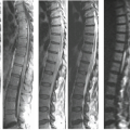
 FIGURE 22.15 Burst fracture of L1 with multilevel axial loading injuries. Sagittal FSE T2-weighted image with fat suppression shows loss of stature of the L1 vertebral body consistent with a burst-type fracture. There is rotation of a fracture fragment which compromises the spinal canal. Note the increased signal in the endplates of the adjacent vertebral bodies of T10–T12 and L2–L4 indicative of compressive marrow injury. (From Flanders AE. Magnetic resonance imaging of acute spinal trauma. In: Schwartz ED, Flanders AE, eds. Spinal Trauma: Imaging, Diagnosis, and Management. Philadelphia, PA: Lippincott Williams & Wilkins; 2007:188–253, with permission.) |
Ligamentous and Joint Disruption
MRI is the only imaging modality available that directly visualizes changes to the ligaments as a result of trauma. The ligamentous structures that are readily identified on routine sagittal MRI of the spine includes the anterior longitudinal ligament (ALL), posterior longitudinal ligament (PLL), ligamentum flavum (LF), and interspinous ligaments (ISP) (Fig. 22.17). They are relatively avascular structures composed primarily of strong fibroelastic tissue with very short T2 relaxation properties. Therefore, ligaments appear relatively hypointense to other structures on all MRI pulse sequences. When overstretched or ruptured, a gap in the ligament may be identified and the surrounding tissues may increase in signal intensity on T2-weighted or GE images because of an increase in free water content from extracellular fluid and/or adjacent hemorrhage (11,12,15). Because of the similarity in imaging characteristics, distinction between a ligament fragment and cortical bone fragment may prove difficult on MRI (15,50).
The longitudinal ligaments are solitary, continuous strips of fibroelastic tissue that extend from the skull base to the sacrum (Fig. 22.17). They function to maintain vertebral body alignment and provide elasticity during flexion, extension, and rotation. Failure of either ligament at any spinal level is indicative of spinal instability (Figs. 22.18–22.31). On MRI, the ALL is a thin, continuous band of low signal intensity
that lies ventral to the anterior cortical surface of the vertebral bodies (57,58,59). The ALL is a critical component which defines the anterior column in the thoracolumbar spine which includes the anterior one-half of the vertebral body and annulus fibrosis. Normally, the ALL may be indiscernible from the cortex or the outer annulus of the intervertebral disc; however, when elevated by fluid, disc, or bone, it may be more apparent (Figs. 22.19 and 22.21) (59). Portions of the ligament merge with Sharpey’s fibers at the vertebral endplate and with the outer annular fibers. The ALL may rupture as the result of hyperextension injury (Figs. 22.26–22.27) (16,57,60,61,62). This is seen on all pulse sequences as a focal discontinuity of the hypointense band that is adherent to the ventral aspect of the vertebral bodies (Figs. 22.23–22.25). This finding may be associated with an avulsion of the vertebral endplate (Figs. 22.21–22.23) or hemorrhage in the prevertebral musculature (16,57,60,61,62). The accumulation of hemorrhage and fluid in the prevertebral space is seen on T2-weighted or GE sequences as a crescent-shaped mass of high signal intensity centered over the segment of injured ligament (Figs. 22.20, 22.22–22.24) (18,21,57).
that lies ventral to the anterior cortical surface of the vertebral bodies (57,58,59). The ALL is a critical component which defines the anterior column in the thoracolumbar spine which includes the anterior one-half of the vertebral body and annulus fibrosis. Normally, the ALL may be indiscernible from the cortex or the outer annulus of the intervertebral disc; however, when elevated by fluid, disc, or bone, it may be more apparent (Figs. 22.19 and 22.21) (59). Portions of the ligament merge with Sharpey’s fibers at the vertebral endplate and with the outer annular fibers. The ALL may rupture as the result of hyperextension injury (Figs. 22.26–22.27) (16,57,60,61,62). This is seen on all pulse sequences as a focal discontinuity of the hypointense band that is adherent to the ventral aspect of the vertebral bodies (Figs. 22.23–22.25). This finding may be associated with an avulsion of the vertebral endplate (Figs. 22.21–22.23) or hemorrhage in the prevertebral musculature (16,57,60,61,62). The accumulation of hemorrhage and fluid in the prevertebral space is seen on T2-weighted or GE sequences as a crescent-shaped mass of high signal intensity centered over the segment of injured ligament (Figs. 22.20, 22.22–22.24) (18,21,57).
 FIGURE 22.16 Symptomatic spondylolysis in young athlete. Fat-suppressed MRI in sagittal (A) and axial (B) planes shows high signal of marrow edema in right pars interarticularis. The irregular linear low signal microfractures can be difficult to distinguish from vascular markings (arrows). Also note minimal hyperintensity in contralateral pars, possibly due to bilateral stress fractures. |
 FIGURE 22.17 Diagrammatic representation of the ligamentous structures in the spine. (From Oatis CA. Kinesiology—The Mechanics and Pathomechanics of Human Movement. Baltimore, MD: Lippincott Williams & Wilkins; 2004, with permission.) |
Unlike the ALL, the PLL is much more variable in width. The PLL is widest at the level of the intervertebral disc and thinner as it passes behind the vertebral bodies (58). Therefore, the PLL may normally appear discontinuous on sagittal MRI images (18). The PLL is represented on MRI as a thin, hypointense band that is interposed between the ventral dural sac and the posterior margin of the vertebral bodies and intervertebral discs (Fig. 22.17). The PLL is the principal ligament of the thoracolumbar middle column that includes the posterior one-half of the vertebral body and the annulus fibrosis. The PLL is best visualized on T2-weighted and intermediate-weighted sagittal images; however, the PLL is often impossible to resolve as a separate structure from the ventral dura or annulus on midsagittal images. The PLL is better delineated when elevated away from the posterior cortex by a herniated disc or posttraumatic
fluid collection (Figs. 22.18–22.21, 22.23–22.25, and 22.28). As with the ALL, rupture of the PLL is identified as a focal region of discontinuity. Typically, rupture of the PLL occurs in hyperflexion- and hyperextension-type injuries.
fluid collection (Figs. 22.18–22.21, 22.23–22.25, and 22.28). As with the ALL, rupture of the PLL is identified as a focal region of discontinuity. Typically, rupture of the PLL occurs in hyperflexion- and hyperextension-type injuries.
 FIGURE 22.18 Fracture dislocation at T12–L1. Sagittal FSE T2-weighted images show the associated soft tissue components to this injury. The ALL is torn at the L1 level (white arrow). The free end of the ruptured LF is demonstrated (curved black arrow). The PLL is disrupted and a portion of the attached bone fragment that has rotated into the spinal canal (black arrow) is displacing the conus medullaris. A small region of edema is noted within the spinal cord (small black arrows). The interspinous and supraspinous ligaments are also disrupted (dotted white arrow). (From Flanders AE. Magnetic resonance imaging of acute spinal trauma. In: Schwartz ED, Flanders AE, eds. Spinal Trauma: Imaging, Diagnosis, and Management. Philadelphia, PA: Lippincott Williams & Wilkins; 2007:188–253, with permission.) |
 FIGURE 22.19 Fracture dislocation at T11–T12 with locked facets. A: Sagittal intermediate-weighted FSE image shows subluxation and angulation at T11–T12. There is a fracture deformity of the T12 vertebral body. The disc at T11/T12 is damaged with interruption of the annulus anteriorly (curved white arrow) and posteriorly (long black arrow). There is an anterior disc herniation that appears contained by the ALL (large white arrow). The LF is ruptured (black arrows). A hematoma is present in the ventral epidural space (asterisk) that extends cephalad from the disc injury. B: Parasagittal intermediate-weighted FSE image shows the right inferior facet of T11 dislocated anterior to the superior facet of T12 (curved arrow). The same finding was present on the left side. C: Axial intermediate-weighted FSE image of T11 demonstrates the abnormal relationship of the facet joints. The inferior facet surfaces (curved arrows) are displaced anterior to the superior facet surfaces (arrows). Note the edema in the central gray matter of the spinal cord (long arrow). (From Flanders AE. Magnetic resonance imaging of acute spinal trauma. In: Schwartz ED, Flanders AE, eds. Spinal Trauma: Imaging, Diagnosis, and Management. Philadelphia, PA: Lippincott Williams & Wilkins; 2007:188–253, with permission.) |
 FIGURE 22.20 Flexion–rotation injury at C4–C5. A: Sagittal FSE T2-weighted image. The body of C4 is subluxed relative to C5. A moderate-sized disc herniation (curved black arrow) has impacted on the swollen and edematous spinal cord. No blood products are identified in the spinal cord. Note the separation of the PLL from the midportion of the C4 body (long black arrow). The ventral dura margin is represented by a thin hypointense line (small black arrows). There is associated disruption of the ligamentum flavum (black arrow) and the interspinous ligaments (asterisk). Prevertebral edema is also present (white arrow). B: Right parasagittal image (same sequence as A). The right C4 inferior facet is jumped and locked in front of the C5 superior facet (arrow). C: Unilateral facet dislocation at C3–C4 in another patient. There is increased fluid within the joint capsule in the subluxed facet joint (white arrow). Note the incidental thrombosed right vertebral artery (dotted arrows). |
 FIGURE 22.21 Complete dislocation at T12–L1. (A): Sagittal intermediate-weighted FSE image. The body of T12 is dislocated relative to L1. The T12/L1 disc is avulsed and free edges of the annular fibers are demonstrated (white arrows). The PLL is discontinuous. The posterior ligamentous complex is disrupted (asterisk). The spinal cord is markedly distorted and compressed at the level of the dislocation (open arrow). Hematoma is present in the anterior epidural space. The ALL is stretched over the dislocated segments (curved black arrow). B: Axial T1-weighted image shows the avulsed disc (arrows) displaced anteriorly to the L1 vertebral body. The spinal cord (open arrow) is draped over the vertebral body. Note the absence of the posterior elements. |
 FIGURE 22.22 Flexion tear-drop fracture of C5 with severe SCI. A: Lateral radiograph shows the typical tear-drop configuration of the C5 vertebral body (arrow) in which a large anterior bone fragment is disassociated from the vertebral body from combined axial loading and flexion. B: Sagittal FSE T2-weighted image shows a flexion tear-drop fracture of the C5 vertebral body with avulsion of a fragment ventrally (white arrow). There is prevertebral soft tissue swelling (dotted white arrow). The ligamentum flavum (LF) and posterior ligamentous complex is ruptured (small black arrow) and the posterior musculature is edematous (asterisk). An extensive intramedullary hemorrhage is present (dotted black arrows). C: Sagittal gradient-echo image shows the extensive hypointense intramedullary hemorrhage (dotted black arrows). |
 FIGURE 22.23 Fracture dislocation at C6 in a 29-year-old man. A: Sagittal T2-weighted image reveals a horizontal fracture line that extends through the C6 vertebral body (arrow). There is offset of the upper segment relative to the lower segment. Spinal cord edema is present, extending the length of three vertebral segments. There is a mound of prevertebral soft tissue swelling/hemorrhage (asterisk). B: Sagittal FSE T2-weighted image shows the details of the injury with better clarity than the SE image. There is disruption of the ALL (curved white arrow), the PLL (curved black arrow), and the LF (straight black arrow). Note that the borders defining the spinal cord edema are better defined than in A. C: Parasagittal FSE T2-weighted image shows distraction of the C6 and C7 facet joints on the right (curved arrow). |
 FIGURE 22.24 Multi-column ligamentous disruptions and spinal instability. A: Sagittal reformatted image from multi-detector CT study is limited by artifact. There are extensive degenerative changes noted but no gross evidence of malalignment. B: Sagittal T2-weighted image shows a previously unsuspected instability with anterior angulation deformity at C6–C7 and subluxation. The ALL (white arrow), LF (black arrow), and PLL (dotted arrow) are disrupted. There is widening of the interspinous distance. Note that none of these findings are evident on the CT image. C: Sagittal STIR (fat-suppressed inversion recovery sequence) shows the edema in the posterior paraspinal soft tissues (asterisk) which is not clearly depicted in the nonfat-suppressed sequence in (B). Note that the damaged intervertebral disc is hyperintense. A prevertebral hematomas is also noted (white arrow). |
 FIGURE 22.25 Multi-column ligamentous disruption secondary to a bilateral interfacetal dislocation (BID) with and without SCI. A: Sagittal T2-weighted MR image shows the marked anterior subluxation of C6 relative to C7. The C6–C7 intervertebral disc is macerated (asterisk) and a portion of it is herniated anteriorly likely intermixed with hemorrhage. A portion of the disc is herniated posteriorly (dashed white arrow). The anterior-superior corner of C7 is fragmented. The anterior longitudinal ligament (ALL) is distorted and stretched (white arrow) and is peeled off the anterior cortex. The posterior longitudinal ligament (PLL) is also stretched and pulled away from the posterior cortical margin (dotted white arrow). The ligamentum flavum (LF) is ruptured (black arrow). A sizable spinal cord injury is present spanning from C4 to C7 comprised primarily of swelling and edema (curved white arrow). B: Sagittal T2-weighted MR image using fat suppression in another patient with a BID-type injury and complete ligamentous disruption and the anterior and posterior columns. Note that the spinal cord shows no intrinsic signal abnormality and this patient was neurologically intact. (From Flanders AE. Magnetic resonance imaging of acute spinal trauma. In: Schwartz ED, Flanders AE, eds. Spinal Trauma: Imaging, Diagnosis, and Management. Philadelphia, PA: Lippincott Williams & Wilkins; 2007:188–253, with permission.) |
 FIGURE 22.26 Hyperextension strain injury at C3/C4. A: Sagittal FSE T2-weighted image shows anterior widening of the C3/C4 disc space and an associated prevertebral hematoma (curved arrow). There is buckling of the LF (arrow). A discrete area of spinal cord edema is also present. B: Axial GE axial images show deformity of the right posterolateral aspect of the thecal sac by the buckled LF. The spinal cord was compressed between the vertebral body anteriorly and the LF posteriorly. |
 FIGURE 22.27 Extension mechanism injury at C5/C6. A: Sagittal FSE T2-weighted image shows changes of multilevel degenerative cervical spondylosis and stenosis spanning C3–C6. There is acute widening of the anterior aspect of the C5–C6 disc space (curved arrow) and the disc material is hyperintense secondary to injury. Spinal cord edema is also present. B: Axial GE axial image obtained through the C5–C6 interspace shows the retropulsed spondylotic disc fragment (arrow) compressing the thecal sac. C: Sagittal T2-weighted image in a different patient shows extension type injury at two distinct levels (C4/C5 and C6/C7). Note the anterior widening of the interspaces with increased signal in the damaged discs (arrows). There is a large prevertebral hematoma (asterisk). (From Flanders AE. Magnetic resonance imaging of acute spinal trauma. In: Schwartz ED, Flanders AE, eds. Spinal Trauma: Imaging, Diagnosis, and Management. Philadelphia, PA: Lippincott Williams & Wilkins; 2007:188–253, with permission.) |
 FIGURE 22.28 Hyperflexion mechanism injury at C3–C4 in a 15-year-old male following a wrestling injury. A: Sagittal T1-weighted image shows acute angulation of C3 on C4 with spinal cord compression. B: Sagittal T2-weighted FSE image shows a large herniated disc fragment (arrow) compressing the spinal cord with the free edge of the ruptured PLL adjacent to the disc fragment. The posterior elements are splayed apart and there is rupture of the interspinous ligaments and ligamentum flavum (asterisk). Spinal cord edema is present from C2 to C5. C: Parasagittal T2-weighted FSE image shows a perched C3–C4 facet complex (arrow). |
 FIGURE 22.29 Hyperflexion injury associated with ligamentum flavum and posterior ligamentous complex rupture. A: Sagittal intermediate-weighted image shows discontinuity of the ligamentum flavum at the C6–C7 level (arrow). B: Sagittal T2-weighted image with fat suppression shows the discontinuity of the LF (arrow) and edema in the posterior paraspinal musculature (star). (From Flanders AE. Magnetic resonance imaging of acute spinal trauma. In: Schwartz ED, Flanders AE, eds. Spinal Trauma: Imaging, Diagnosis, and Management. Philadelphia, PA: Lippincott Williams & Wilkins; 2007:188–253, with permission.) |
 FIGURE 22.30 Isolated rupture of the posterior ligamentous complex (PLC) at the thoracolumbar junction. A: Sagittal MPR CT image of the thoracic spine shows a wedge deformity of the T12 vertebral body. There is widening of the interspinous distance at T11–T12. Note that the posterior cortex of T12 is intact indicating no failure of the middle column. B: Sagittal T2-weighted image of the thoracic spine with fat suppression shows marrow edema in the T12 segment as well as in the adjacent L1 body (white arrow). The ligamentum flavum (LF) is disrupted (curved black arrow) and there is extensive soft tissue injury in the posterior paraspinal soft tissues (gray arrows). C: Axial T2-weighted image at the T12 level shows the high signal intensity in the posterior paraspinal soft tissue indicative of edema/hemorrhage (black asterisk) compared to the normal adjacent paraspinal muscles (white asterisk). (From Flanders AE. Magnetic resonance imaging of acute spinal trauma. In: Schwartz ED, Flanders AE, eds. Spinal Trauma: Imaging, Diagnosis, and Management. Philadelphia, PA: Lippincott Williams & Wilkins; 2007:188–253, with permission.) |
 FIGURE 22.31 Dorsal epidural hematoma from ligamentum flavum rupture. Sagittal fast spin-echo (FSE) T2-weighted images. A large dorsal epidural hematoma is displacing the posterior margin of the dura (small black arrows). The hematoma is heterogeneous with both hypointense and hyperintense components. The hematoma likely originates at the site of rupture of the ligamentum flavum at the L2 level. The roots of the cauda equina are compressed against the vertebral body by the hematoma (white arrows). (From Flanders AE. Magnetic resonance imaging of acute spinal trauma. In: Schwartz ED, Flanders AE, eds. Spinal Trauma: Imaging, Diagnosis, and Management. Philadelphia, PA: Lippincott Williams & Wilkins; 2007:188–253, with permission.) |
 FIGURE 22.32 Unilateral interfacetal dislocation at C4–C5. A: Sagittal T2-weighted (2,000/90/ETL 8) FSE image with fat suppression shows anterior subluxation of C4 on C5 with disc disruption and anterior herniation of disc material (arrow). Note the edema in the posterior paraspinal musculature (asterisk) related to the rotational component of the injury. B: Right parasagittal intermediate-weighted image shows the abnormal orientation of the C4 inferior articular process located anterior and inferior to the C5 superior articular process (arrow). C: Gradient-echo axial image obtained through the C4–C5 disc space shows the abnormal morphology of the right facet joint (arrow) compared to the left. |
The LF forms a continuous strip of fibroelastic tissue that bridges adjacent lamina (Fig. 22.17). Along with the ISP, they act as check ligaments to oppose hyperflexion and distraction of the posterior elements and maintain alignment. They are the principal ligaments of the posterior column which includes all of the posterior elements. Normally, the LFs are small structures (especially in the cervical and thoracic regions), which are oriented parallel to the adjacent lamina. Focal discontinuity of the LF can be identified on the parasagittal MR images (Figs. 22.29–22.31). The LF may enlarge either on a degenerative basis or physiologically by bulging into the spinal canal in hyperextension. LF rupture is often associated with fractures of the posterior elements. The injured LF can be easier to visualize when the damaged segment projects into the spinal canal and distorts the posterolateral aspect of the thecal sac. This finding is best visualized on parasagittal images (Figs. 22.18–22.20, 22.22–22.25, and 22.28–22.31).
Disruption of the ISP is best appreciated on the fat-suppressed midsagittal T2-weighted views. Fat suppression is essential for the detection of the typical high signal intensity in the tissues interposed between the widened spinous processes (Figs. 22.18, 22.20–22.30, and 22.32) (15). The supraspinous ligament (SSL) forms a long contiguous band connecting the tips of the adjacent spinous processes and also serves as a posterior tension band that resists hyperflexion (Fig. 22.17). The ruptured free edge of this structure may be visible within the edematous posterior paraspinal soft tissues (Fig. 22.18).
The facet joint complexes are easily identified on sagittal and axial images, particularly in the cervical and lumbar regions where the structures are somewhat larger in size and the joint plane is oriented in the sagittal direction. In the thoracic spine, the facet joints are small in size and the joint is oriented in the coronal plane.
The facet joint complex is a dynamic structure that permits limited compression and distraction of the posterior elements during extension and flexion while resisting rotation and translation. Although fractures that involve the facet surfaces are better detected with MDCT, subtle damage to the synovial capsule and cartilaginous surface of the joint is best appreciated with MRI. The facets are demonstrated on the far left and right parasagittal images of a well-centered sagittal sequence. The articular surface of the superior facet normally maintains close apposition to the inferior facet surface. Widening of this space is suggestive of a distraction injury (Fig. 22.23). The imaging criteria of altered facet alignment or subluxation is similar to the plain film appearance (Figs. 22.19, 22.20, 22.23, 22.29, 22.32, and 22.33). Increased
fluid within the joint space is suggested by a well-demarcated hyperintense focus interposed between the articular surfaces on T2-weighted and GE images (Fig. 22.20). The increased fluid is contained within the joint space and joint capsule.
fluid within the joint space is suggested by a well-demarcated hyperintense focus interposed between the articular surfaces on T2-weighted and GE images (Fig. 22.20). The increased fluid is contained within the joint space and joint capsule.
 FIGURE 22.33 Interfacetal dislocation. Sagittal fast spin-echo (FSE) T2-weighted image. There is fracture deformity of the T7 vertebral body with loss of height anteriorly. The marrow signal of T7 is hyperintense secondary to compressive injury (asterisk). The right T6–T7 facet joint is disrupted (curved arrow). |
Disc Injury
The identification and classification of a traumatic disc injury are important factors in determining the timing of and type of surgical decompression and stabilization (63,64). Although posttraumatic disc herniation does not correlate with the degree of associated injuries or neurologic deficit, unrecognized disc herniation is a cause of neurologic deterioration after stabilization (9,63,64,65). Noncontrast CT is relatively insensitive to disc herniation as compared to MRI; however, the high-resolution and isotropic datasets produced with MDCT often routinely depicts disc herniations and the soft tissue contents of the spinal canal (9,12,52,63).
Although degenerative disc herniations are probably more common in the lumbar spine, posttraumatic disc herniations are encountered more frequently in the cervical and thoracic regions (16,55,64). In the cervical region, disc herniations most commonly occur at the C4–C7 levels (9,66). The incidence of posttraumatic thoracic disc herniations are more common than previously estimated—they occur in up to 50% of thoracic injuries (64). Prior to the general use of MRI, cervical disc herniations were estimated to occur in only 3% to 9% of all cervical spine injuries. In addition, a large number of false-positive cervical disc herniations were reported using CT and myelography alone (64). With the routine use of MRI, the reported incidence of cervical disc herniation is reported as high as 54% (9,63,65,66). Cervical disc herniations are associated with 80% of bilateral facet dislocations, 60% of hyperextension injuries, 47% of central cord injuries, and all cases of anterior cord syndromes (63). Twenty-two percent of neurologically normal patients demonstrated disc herniations on MRI after trauma (66). Cervical disc herniation is reported to occur more frequently in flexion-distraction and flexion-compression type injuries (67). The existence of thecal sac compression by herniated disc material is a significant factor in determining whether a discectomy should be performed at the time of surgical stabilization (63,67). In addition, residual spinal cord compression from a posttraumatic disc herniation is associated with more severe neurologic injuries than disc herniation without cord compression (9,68,69). However, Dai et al. (63) refuted this by finding no significant relationship between neurologic deficit or neurologic recovery rate and severity of spinal cord compression by herniated disc material. Nevertheless, the authors concluded that surgical management is advised when residual spinal cord compression is demonstrated on MRI (63).
Posttraumatic disc changes on MRI can be classified as either disc injury or disc herniation. Normally, the well-hydrated intervertebral disc is hypointense relative to bone marrow on T1-weighted images and intermediate in signal on T2-weighted FSE images. The nondegenerated disc is uniform and symmetric in height and the peripheral fibers of the annulus fibrosus merge imperceptibly with the longitudinal ligaments. Disc injury is implied whenever there is asymmetric narrowing or widening of an isolated disc space on sagittal images and focal hyperintensity of the disc material on T2-weighted images. The injured disc is often higher in signal intensity than the adjacent discs on T2-weighted images and the level of injury is usually contiguous with other damaged tissues (Figs. 22.20, 22.24, 22.27, and 22.32). The observed signal changes in the disc may be the result of tearing of the disc substance during hyperflexion, hyperextension, or subluxation (9,18,57). As the adult intervertebral disc is an avascular structure, the observed, potentially hemorrhagic MR signal changes of a damaged disc may, therefore, be, in part, due to damage to the adjacent endplates. The signal changes of the injured disc may be easier to identify in patients with hypointense discs from pre-existing degenerative disc disease (Fig. 22.27).
An acute, posttraumatic disc herniation has a similar MRI appearance to nontraumatic disc herniation. The nucleus pulposus is forced under pressure to extrude into the peripheral annulus fibrosus and, in some instances, extend beyond the outer annulus into the anterior epidural space. The herniation may be broad-based or eccentric and may or may not be associated with a vertebral body fracture. On sagittal MRI images, the disc herniation is isointense and contiguous with the disc of origin (2,7,9,12,14,17,18). A small herniated disc fragment often appears as a focal area of expansion of the annulus beyond the border of the posterior cortical margin (Figs. 22.20, 22.28, 22.34, and 22.35). Occasionally, a small rent in the annulus may appear that allows passage of nuclear material into the epidural space. On axial images, the herniated disc produces focal distortion of the ventral theca (Fig. 22.34). Depending on the size and location of the disc herniation, the fragment may be demonstrated on multiple sagittal and axial images.
The degree of compressive injury to the neural elements depends on the size of the herniated fragment, the width of the spinal canal at the level of injury, and the diameter of the spinal cord. For example, a small disc herniation in the thoracic region may cause more neural impingement than an identical fragment would cause in the lumbar or cervical regions (70).
Identification of an acute disc herniation can be difficult in the setting of superimposed degenerative spondylotic changes (16). In such instances, multiple chronic spondylotic disc herniations associated with osteophytes may complicate the correct identification of an acute traumatic disc herniation (21). Imaging factors that may aid in the identification of an acute disc herniation with superimposed spondylosis include alteration in signal of the disc material at one level, asymmetric width of the intervertebral disc space, subluxation, and associated injuries at the same level (Fig. 22.27). In some circumstances, definitive identification may be impossible.
Epidural Hematoma
The incidence of asymptomatic posttraumatic spinal epidural hematomas is greater than was previously recognized (15). They have been reported to occur in up to 41% of spine injuries (15). Spinal epidural hematomas occur as the result of tearing of a portion of the epidural venous plexus with focal extravasation of blood into the anterior epidural space. Most epidural hematomas from closed trauma are found in association with other injuries, are relatively small in size, and are probably not clinically significant (18). Since the spinal dura is not firmly adherent to the vertebral canal, relatively large epidural hematomas may remain clinically silent because they extend over multiple levels and therefore they do not result in substantial compromise to the thecal sac and contents. The imaging characteristics of epidural hematomas are variable as they depend on the oxidative state of the hemorrhage and the effects of clot retraction (Figs. 22.10, 22.19, 22.31, 22.34, 22.36, 22.38, and 22.39) (55,71,72). In the acute phase, the epidural hematoma is isointense with spinal cord parenchyma on T1-weighted images and isointense with CSF on intermediate- and T2-weighted sequences (2). In some instances, an epidural hygroma forms which may be difficult to distinguish from the adjacent CSF in the subarachnoid space (Figs. 22.37 and 22.38). This distinction can often be made by the hypointense dura, which separates the two compartments (Figs. 22.34, 22.37, and 22.39). The reported incidence of posttraumatic epidural hematoma in patients with ankylosing spondylitis (AS) is greater than in the general population, ranging from 10% to 50% and occur more often in the posterior epidural space (Fig. 22.39) (73).
 FIGURE 22.34 Traumatic disc herniation with epidural hematoma. A: Sagittal SE T1-weighted image shows interruption of the posterior annulus at the C6/7 level (white arrow). A mound of tissue projects behind and above the disc space (curved arrow) representing herniated material bounded by the elevated PLL. The associated epidural hematoma (small arrows) is minimally hyperintense. Also note the marked swelling of the spinal cord. B: Sagittal SE image shows that the epidural fluid collection is hyperintense. The margins around the herniated disc are better demonstrated (black arrow). Note the associated interruption of the ALL (white arrow). C: Axial 3DFT GE image in another patient shows a large extruded disc fragment (asterisk) that is compressing the right anterior margin of the thecal sac (arrows). |
 FIGURE 22.35 Large posttraumatic disc herniation with epidural hematoma. A: Sagittal CT MPR image shows a hyperdense soft tissue mound extending into the spinal canal and compromising the anterior epidural space (arrows). B: Sagittal intermediate-weighted MR image shows discontinuity of the posterior annulus at C4–C5 (black arrow) and an epidural tissue mound spanning the C4 and C5 vertebral bodies which compromises the spinal canal (white arrows). Note that disc material cannot be distinguished from hematoma. C: Off-midline sagittal T2-weighted MR image with fat suppression shows the herniated disc fragment that is not discernable on the other images. The remainder of the mound of tissue represents a combination of epidural hemorrhage and congested epidural venous plexus. Also note the complete disruption of the posterior paraspinal soft tissues (asterisk). |
 FIGURE 22.36 Large epidural hematoma. A: Sagittal FSE intermediate-weighted image. There is a fracture of the T12 vertebral body with resultant kyphous deformity of the spine. The ALL is ruptured at the T12 level (white arrow). A large hyperintense fluid collection is present in the ventral epidural space that extends caudally to approximately the L3 level (asterisks). There is marked compression of the thecal sac (curved arrow). B: Axial T1-weighted image. The epidural hemorrhage is forcing the thecal sac dorsally and causing severe compression of the conus medullaris (arrows). |
 FIGURE 22.37 Large epidural collection following C2 fracture. A: Sagittal T1-weighted image shows a markedly widened ventral subarachnoid space. The spinal cord is displaced posteriorly (arrows). (B): Sagittal intermediate-weighted image shows that the widened epidural space (asterisks) contains fluid that is somewhat hyperintense relative to CSF. The hypointense band (arrow) represents the ventral dura. (C): Sagittal T2-weighted image shows a large epidural fluid collection (asterisks) separate from normal CSF that is displacing the spinal cord dorsally (arrows). The collection is bounded by dura as the PLL appears intact. There is diffuse high signal intensity within the spinal cord parenchyma from edema. Note that the deformity of the odontoid process is very difficult to appreciate (curved white arrow). There is associated rupture of the interspinous ligaments between C1 and C2 (curved black arrow). |
 FIGURE 22.38 Unusual dorsal thoracic epidural hematoma not associated with a fracture in a 32-year-old woman after a fall. A: Sagittal FSE T2-weighted image shows a dorsal hyperintense epidural fluid collection which spans multiple segments of the thoracic spine (arrows). B: Contrast-enhanced axial T1-weighted image shows the low–signal-intensity hematoma (asterisk) compressing the thecal sac. |
 FIGURE 22.39 Dorsal epidural hematoma in patient with ankylosing spondylitis. A: Oblique axial CT image through lower cervical spine shows a large biconvex hyperdense collection (asterisk) dorsal to the thecal sac. The theca is displaced anteriorly (arrows). B: Axial FSE MRI images confirm the presence of the epidural hematoma (asterisk) and the compression of the posterior dura (arrows). C: Sagittal FSE T2-weighted image shows the broad extent of the hemorrhage through the entire cervical region (arrows). The heterogeneous signal characteristics are secondary to heme in various stages of evolution. The accentuated configuration of the cervical spine is secondary to ankylosing spondylitis. |
Vascular Injury
The true incidence of associated posttraumatic dissection or thrombosis of the extracranial carotid and vertebral arteries following cervical spine injury is unknown because the vascular injury often remains clinically occult. Prior investigations have suggested that damage to the vertebral arteries can be demonstrated with angiography in up to 40% of patients following cervical subluxation/dislocation (74). Dissection of the vertebral artery is more frequent than carotid artery dissection following fracture/subluxation because a portion of the cervical vertebral artery is contained within the foramen transversarium. A fracture that extends through the foramen transversarium may compress the ipsilateral vertebral artery. Because the artery is fixed within the foramen, it may also be subject to severe stretching and torsional forces from cervical subluxation (Figs. 22.20C, and 22.40–22.42) (75,76).
Early recognition of vertebral artery injury remains important because of its potential to produce significant neurologic comorbidity and permanent neurologic damage. Moreover, the secondary injury is potentially preventable with early institution of therapy (e.g., anticoagulation, embolization, or surgical ligation) (77). The incidence of isolated vertebral artery injury in the setting of cervical spine trauma is not well known because the patient is frequently asymptomatic at the time of injury (78).
In a prospective study of 47 cervical spine trauma patients, Parbhoo et al. (78) reported that 26% (n = 12) of the patients showed vertebral artery damage on MRI/MRA; in 9 patients (19%), the vertebral artery was thrombosed. Most of the patients with vertebral artery injury (n = 10) had an associated unilateral facet dislocation (78).
Willis et al. (79) prospectively selected 26 patients with bony injuries associated with vertebral artery injury and found vertebral artery thrombosis (VAT) in 9 patients (35%), normal VA in
14 patients (54%), and dissection in 3 patients (11%) by using angiography; SCI was present in half of the patients, and no neurologic sequelae were attributed to the arterial injuries.
14 patients (54%), and dissection in 3 patients (11%) by using angiography; SCI was present in half of the patients, and no neurologic sequelae were attributed to the arterial injuries.
 FIGURE 22.40 Clinically occult vertebral artery thrombosis after unilateral facet dislocation (UID) at C5–C6 without spinal cord injury at C5–C6 without SCI. A: Sagittal T2-weighted fast spin-echo (FSE) image shows an injured disk at C5–C6 with increased signal intensity in the disk and probably avulsion of the anterior longitudinal ligament (dashed arrow). Prevertebral edema (arrowheads) and edema in the posterior paraspinal musculature (white arrows) are present. B: Nonvisualization of the right vertebral artery. MIP image (anterior view) from a 2D time-of-flight MRA acquisition shows absence of signal intensity in the expected course of the right vertebral artery (dotted line). C: Thrombus in the right foramen transversarium. Axial image from a 3D GRE acquisition shows an oval area of low signal intensity in the right foramen transversarium corresponding to thrombus in the right vertebral artery. Note the normal flow-related enhancement in the left foramen transversarium. D: Thrombus in the right vertebral artery. Axial FSE image obtained at a similar level to image in panel (C) shows a high–signal-intensity thrombus (arrow) in the right foramen transversarium indicative of a thrombosed vertebral artery. Note the normal flow void of the left vertebral artery. (From Torina PJ, Flanders AE, Carrino JA, et al. Incidence of vertebral artery thrombosis in cervical spine trauma: correlation with severity of spinal cord injury. AJNR Am Soc Neuroradiol 2005;26:2645–2651, with permission.) |
 FIGURE 22.41 Crush injury from fork lift in a 49-year-old man. A: Sagittal fast spin-echo (FSE) T2-weighted image shows a massive hemorrhagic injury of the cervical spinal cord. The edema extends up to the level of the foramen magnum. A disc herniation is present at C4–C5 (white arrow) and there is offset of the cervical segments at that level. The ligamentum flavum is disrupted at the C4 level (black arrow). Note the sharp change in caliber of the spinal cord caudally (small black arrow). B: Axial FSE T2-weighted images at the C3–C4 level shows buckling of the lamina with encroachment on the posterior epidural space (open black arrow). The spinal cord is enlarged, deformed, and devoid of all normal internal anatomic features. Portions of the central gray matter are hypointense secondary to hemorrhage (long white arrows). Note the absence of normal flow void in the left vertebral artery (curved white arrow) and left internal carotid artery (open white arrow) suggestive of slow flow or occlusion (compare with normal right side). C: Axial computed tomographic image at the C4 level shows comminuted fractures of the lamina bilaterally with resultant narrowing of the spinal canal. D: Maximum intensity projection image from axial 2D time-of-flight MRA acquisition reveals normal flow-related enhancement of the right carotid artery and right vertebral artery with absence of the left carotid and vertebral arteries. E: Right posterior oblique view from arch arteriography confirms the traumatic occlusion of the left common carotid artery (open arrow) and left vertebral artery (curved arrow). |
 FIGURE 22.42 Traumatic intimal injury of vertebral artery. A: AP radiograph from a left vertebral arteriogram shows irregularity of the lateral wall (arrows) of the contrast column secondary to distractive injury at C3–C4. (No associated fracture at this level.) B: Single projection from a 2D TOF MRA shows normal flow-related enhancement in all vessels. There is minimal irregularity of the left vertebral artery (arrow) but the intimal damage is not apparent. C: Axial 3DFT GE images in another patient with traumatic occlusion of the left vertebral artery. Hypointense acute clot is demonstrated within the lumen of the left vertebral artery (arrows). Compare with normal flow-related enhancement in the right vertebral artery (open arrows). Also note the massive hemorrhage in the spinal cord (curved arrow). |
In another prospective MRI/MRA study, Friedman et al. (75) identified VAT in 9 (24%) of 37 consecutive cervical SCI patients. VAT was significantly more common in the motor-complete SCI patients than in the motor-incomplete patients.
Using cerebral arteriography, Biffl et al. (80) found 47 vertebral artery injuries in 38 patients in a selected cohort derived from 7,205 consecutive patients (0.53%) admitted with blunt trauma to a single level I trauma center; 350 patients were selected for cerebral arteriography on the basis of mechanism of injury or the existence of acute cerebrovascular symptoms. The most frequent related injury associated with vertebral injury included spine fracture/dislocation (71%), followed by chest and extremity injury (45%). The actual frequency of VAT in the subgroup evaluated with angiography was 2.6%. These authors found no relationship between grade of vertebral artery injury, neurologic deficit, or neurologic outcome (80).
Other investigators have shown a higher incidence of VAT on cerebral arteriography when selecting for patients with specific types of cervical injuries, such as facet joint dislocations (75%; unilateral or bilateral) and foramen transversarium fractures (88%) (3,6). The frequency of VAT was lower overall for similar studies that used MRA as the imaging technique: 33% for patients with foramen transversarium fractures and as high as 24% for multiple contiguous cervical spinal injuries (6,7,15).
There is some disparity in the literature whether the severity of neurologic deficit has a relationship to the frequency of VAT. Giacobetti et al. (81) prospectively reviewed MRA examinations of 61 consecutive cervical spine injuries, finding VAT in 12 (19.7%). Twenty-eight of the 61 patients sustained some form of SCI. The frequency of VAT stratified by American Spinal Injury Association (ASIA) impairment scale included ASIA-A (n = 3), ASIA-B (n = 3), ASIA-D (n = 2), and ASIA-E (n = 4). This suggested that the severity of neurologic injury was not predictive of VAT. No permanent neurologic deficits related to the VAT were identified (81). Six of the patients were reimaged by MRA 12 to 26 months after injury. The vertebral arteries in five patients remained thrombosed on the subsequent MRA study (82).
In the largest retrospective review that evaluated the association of VAT with severity of SCI, Torina et al. (83) assessed the vertebral arteries of 632 patients with nonpenetrating injuries using MRA/MRI. Eighty-three (13%) patients had VAT on the admission MRI/MRA. Fifty-nine percent (49/83) of VAT patients had an associated SCI. VAT was significantly more common in motor-complete patients (ASIA-A and ASIA-B, 20%) than in neurologically intact (ASIA-E, 11%) cervical spine–injured patients (p = .019). VAT incidence was not significantly
different between motor-incomplete (ASIA-C and ASIA-D, 10%) and neurologically intact (ASIA-E, 11%) cervical spine–injured patients (p = .840). They concluded that the absence of neurologic symptoms from the SCI does not preclude VAT (Fig. 22.40). Therefore, MRA evaluation is warranted as part of the routine MRI evaluation of cervical injuries (83).
different between motor-incomplete (ASIA-C and ASIA-D, 10%) and neurologically intact (ASIA-E, 11%) cervical spine–injured patients (p = .840). They concluded that the absence of neurologic symptoms from the SCI does not preclude VAT (Fig. 22.40). Therefore, MRA evaluation is warranted as part of the routine MRI evaluation of cervical injuries (83).
The clinical significance of occult vertebral artery injury is not known; however, in some series the stroke rate has been as high as 54% for untreated vertebral artery injury (82). Biffl et al. (80) reported a posterior circulation stroke rate of 25% in his series of blunt vertebral artery injuries. It is noteworthy that no other published studies report a stroke rate of this magnitude.
Both Miller and Biffl have advocated for prompt angiographic evaluation of selective patients at risk of vascular injury and aggressive management of vertebral artery injury (VAI) with anticoagulation; reporting significant protection from cerebral ischemia and improved neurologic outcomes (80,84). While their reported incidence of vertebral artery injury and secondary cerebral ischemia is substantial, other reports would suggest that the incidence is much lower and that secondary neurologic complications are unusual, particularly with VAT (83).
There is empirical evidence that a 6-month course of anticoagulation offers some protective effect against thromboembolic events and cerebral ischemia from spontaneous carotid or vertebral dissection; however, no well-controlled studies have been performed to support routine use of anticoagulation in this setting (85).
Since the proportion of patients with clinically symptomatic posttraumatic vascular injury is small, conventional angiography cannot be justified to evaluate all patients with cervical trauma for occult vascular injury. However, MRA or CT angiography (CTA) is an appropriate screening test to identify patients who may require subsequent catheter angiography. A 2D time-of-flight sequence used in conjunction with a walking superior saturation pulse used to suppress venous inflow is effective in screening the extracranial vasculature for occlusion. This technique is adequate to evaluate vascular occlusion or significant narrowing; however, resolution limits the effectiveness of detecting subtle intimal injuries associated with dissection (Fig. 22.42). In cases of vertebral artery occlusion, axial GE images reveal replacement of normal flow-related enhancement in the foramen transversarium by a hypointense clot (deoxyhemoglobin) (Figs. 22.40 and 22.42). In contrast, the acute clot appears hyperintense on routine T2-weighted cross-sectional images compared to the normal flow void in the normal artery (Figs. 22.41 and 22.42). The use of black-blood techniques is also advocated to improve detection of subintimal dissections without occlusion. This technique suppresses signal from flowing blood and the surrounding tissues through the use of multiple spatial and chemical saturation pulses which render flowing blood hypointense and subintimal clot as hyperintense (75,83). A comparison of test performance of MRI, MRA, and CTA in the diagnosis of carotid and vertebral artery dissection found relatively similar characteristics for MRI, MRA, and CTA (86).
Biomechanics and Distribution of Injuries
Most SCIs reported in any given year result in tetraparesis due to damage to the cervical spinal cord. The majority of victims of thoracic and lumbar spine trauma suffer no neurologic sequelae (70,87). The type of injuries that occur in the cervical, thoracic, and lumbar regions differs because of regional structural differences, biomechanical variations, and mechanisms of injury. Factors that may predispose to SCI include developmental or acquired spinal stenosis, degenerative spondylosis, and AS (57,62,73,88,89).
The pathophysiology of spinal injury can be better understood in a biomechanical framework (90). The spine is made up of relatively rigid components (vertebral bodies and posterior elements) and flexible components (intervertebral discs and ligaments). All the spinal segments work in concert with the adjacent segments to allow for reasonable amounts of flexion, extension, and rotation. The response of any substance to stretching or compression by an external force is defined by its elastic modulus. The application of too great a force over a short period of time results in tissue stress and eventual failure. Bone and ligament have different failure characteristics (1). The dissipation of a force applied to the spine is well tolerated under the following circumstances: (a) the force is applied gradually over a prolonged period, and (b) the resultant motion of the spine by the force does not exceed the design specifications in terms of length of travel. If either of these rules is violated, then the elastic modulus of the tissues may be exceeded and tissue failure results. This phenomenon is well illustrated in the cervical region: the cervical spine supports a large free weight (the head) that allows for a full range of motion (flexion, extension, and rotation). During periods of rapid acceleration/deceleration, the head develops large amounts of kinetic energy that must be completely dissipated by the cervical spine. In this setting, a lower segment of the cervical spine may behave as a fulcrum against the relatively fixed thoracic spine, resulting in tissue failure. Tissue failure allows for focal dissipation of this kinetic energy; therefore, the osseous, ligamentous, and spinal cord damage tend to be in anatomic proximity (9,57,62).
Classification systems have been developed to help simplify the description of spinal injuries as an aid in diagnosis, prognosis, and treatment (91,92). These systems are used to infer the amount of “invisible” soft tissue damage based on radiographic appearance. Some of these schema are based on mechanisms of injury, that is, hyperflexion, hyperextension, rotation, flexion–rotation, extension–rotation, axial loading, or lateral translation (90). A major limitation of this concept is that few injuries can be explained by “pure” mechanisms. Moreover, the biomechanics of the spine differ drastically by location and, therefore, the types of injuries produced by the same force vectors differ by location. A classification based on mechanism alone does not directly relate either to treatment or prognosis.
Other classification schemes of spinal injury are based solely on the presence of stability or instability of an injury. Potential instability is an important determining factor in the use and type of surgical stabilization. Instability is defined as the loss of ability of the spine to maintain normal anatomic alignment under normal physiologic loads (70,92). The properties of spinal instability are based on the three-column model of thoracolumbar spine trauma suggested by Holdsworth and revised by Denis (91,92). This model was devised so that inferences could be made about the status of soft tissue injury based solely on radiologic changes. In this model, the spine is represented by three columns: the anterior column, which is made up of the anterior one-half of the vertebral body, the anterior annulus fibrosus, and the ALL; the middle column, composed of the posterior half of the vertebral body and the PLL; and the posterior column, which contains the posterior neural arch, LF, facets, and ISP. Isolated disruption of the posterior column does not constitute instability; the structures of the middle column must also be involved to invoke instability in the thoracic and lumbar spines (91).
This type of classification offers information that aids in the diagnosis and treatment of specific injuries, yet it is an oversimplification that is probably not valid biomechanically (70). Tears of the PLL, LF, ISL, and SSL, and facet joint disruption are potentially unstable (94). Some fractures that would be classified as stable can still harbor components that would render the injury unstable if not adequately treated (95). Furthermore, since MRI provides direct visualization of the integrity of the ligamentous complexes, MRI evaluation may supersede standard classification methods when MRI demonstrates unexpected soft tissue injuries.
 FIGURE 22.43 Severe fracture from minor trauma in a 50-year-old with pre-existing diffuse idiopathic skeletal hyperostosis (DISH). A: Sagittal MPR CT image shows posttraumatic subluxation of the C3 segment on C4 with widening of the interspinous distance (arrow) and a large fragmented osteophyte anteriorly (dashed line). Note the extensive bony bridging elsewhere. B: Sagittal MPR CT image shows the associated unilateral interfacetal dislocation. C: Sagittal T2-weighted MR image shows extensive prevertebral edema (asterisk) as well as marrow edema within the C3 and C4 vertebral bodies. There has been damage to the posterior ligamentous complex as well (arrow). There is a small associated posterior epidural fluid collection. Note the absence of injury to the spinal cord. (From Flanders AE. Magnetic resonance imaging of acute spinal trauma. In: Schwartz ED, Flanders AE, eds. Spinal Trauma: Imaging, Diagnosis, and Management. Philadelphia, PA: Lippincott Williams & Wilkins; 2007:188–253, with permission.)
Related posts:Stay updated, free articles. Join our Telegram channel
Full access? Get Clinical Tree
 Get Clinical Tree app for offline access

|