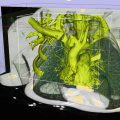
Fig. 58.1
Electromagnetic (EM) position sensors are attached to the head of the endoscope, and a tracker system is used to provide position and orientation signals to the computer. These signals are combined with calibration data and registered to the patient’s body and 3D model to create a display to guide the operator [6–8]. As shown in Table 58.1, we distinguish four key processes that are implemented to create this real-time display
Table 58.1
Characteristics of system elements for image registered procedures
System element and function | Key factors for image registered interventions |
|---|---|
Segmentation. Working from a 3D volumetric examination created by MR or CT, distinguish key anatomic features, and build a solid model of the patient showing those features | Semiautomatic, with minimal trained supervision required; eventually fully automatic |
Model features are appropriate to the particular interventional task | |
Tracking. Provide direct digital information on the spatial location of key elements, such as interventional instruments and, sometimes, the patient | Fast (no lag at video rates) |
Stable (no jitter) | |
Adequate volume | |
Minimal interference with the procedure | |
Capable of being sterilized, easily | |
Registration. Align the patient, the segmented model, and the instrument tracking system so that information from these three sources are geometrically synchronized | Sufficiently accurate (<5 mm) |
Stable | |
Minimal impact on procedure set-up time | |
Compatible with the procedure environment (particularly sterility) | |
Display. Present the model, tracked elements, and image data to the physician operator | Real time, lag-free (20–30 fps) |
Easily understood | |
Solid, extensible software platform | |
High fidelity display |
While this work is enabled by advanced electromagnetic (EM) and/or optical (OP) tracking hardware, the key technical challenges have been in developing robust, high-performance algorithms and software architecture to make tracking systems practical for real-time guidance. The overall goals of these studies have been to demonstrate and use systems that may be added onto a conventional endoscopy system in a standard procedure room without radiologic capability. In addition, to reduce costs and system complexity, only broadly available commercial hardware systems have been used.
Literature Review
In this section we present an overview of available tracked endoscopy and laparoscopy technologies. This provides an overview for those working in the field and as a reference for those searching for literature on technological developments related to navigation in ultrasound-guided laparoscopy and endoscopy. PubMed, Google Scholar, and the IEEE database were searched to identify relevant publications from the last 10 years. Additional publications were identified by manual search through the references from the key papers found. We focus on papers published in the last 5 years. The search was limited to navigated LUS/EUS including variations such as ultrasonography, sonography, and echography, in combination with key words such as navigation, tracking, endoscopy, and 3D ultrasound.
Table 58.2 presents a chronological summary of the literature in the field of navigation. These publications show that navigated LUS has several advantages in laparoscopic guidance compared to conventional 2D LUS, especially due to the orientation challenges. The further advancement of soft tissue navigation requires surgeons, engineers, and radiologists to collaborate more closely, inside and outside the OR. Specific surgical procedures have to be identified, where current technological possibilities will fulfill user demands as a tool for obtaining improved patient care.
Table 58.2
Overview of image-guided system in laparoscopy and endoscopy
Year | Reference | Application space | Technology | |||
|---|---|---|---|---|---|---|
Tracking | Registration | Calibration | Display | |||
2011 | Obstein et al. [9] | EUS: human study for image-guided fine-needle aspiration (FNA) | EM | LM + ICP | PC | 3D models, pre-op CT with US |
Liu et al. [10] | EV: bronchial phantom study for virtual endoscopy | EM | LM | OC | CT fusion with optical view | |
2010 | Fernández-Esparrach et al. [11] | EV: animal study for virtual endoscopy in NOTES | EM | LM + ICP | PC | 3D models, virtual endoscopic view from CT |
Martens et al. [45] | LUS: in vivo study for laparoscopic liver interventions | EM | LM + ICP | CW | 3D view with volume rendering from CT | |
Shekhar et al. [12] | LV: feasibility animal study for optical augmented reality in lap surgery | OPM | OP + II | OC | Virtual endoscopic view from CT | |
2009 | Solberg et al. [13] | LUS: phantom study | EM | LM | SAP | Volume rendering |
2008 | Langø et al. [14] | LUS, LV: platform development | EM | LM | SAP | Volume rendering and 3D models from CT |
Hildebrand et al. [15] | LUS: system for laparoscopic liver therapy | EM | LM | N/A | 3D models from CT | |
Feuerstein et al. [16] | LV: animal study for a port placement system and navigation using a intraoperative C-arm | OP | LM | OC | Volume rendering and augmented endoscopic video | |
2007 | Konishi et al. [17] | LUS and LV: animal study for augmented liver surgery | EM + OP | LM | OC | Augment ultrasound and endoscopic view and virtual endoscopic |
Hildebrand et al. [18] | LUS: ex vivo study for laparoscopic radiofrequency ablation (RFA) of the liver | EM | Not needed | Not needed | 3D environment with US plane and RFA tool | |
San Jose Estepar et al. [19] | LUS, EUS: animal study for image-guided transgastric procedures and laparoscopic examinations | EM | LM | SW | 3D models from CT and reformatted CT in US plane. | |
2006 | Kleemann et al. [20] | LUS: phantom study for US-guided liver dissection | EM | Not needed | Not needed | Tool projected on US plane |
2005 | Krücker et al. [21] | LUS: abdominal phantom study to guide tracked-needle in US laparoscopic interventions | EM | LM | CW | Overlay of US with preoperative CT |
Bao et al. [22] | LUS: phantom study for image-guided laparoscopic liver surgery | OP | LM | SW | 2D US placed in 3D volume rendering from CT | |
2004 | Ellsmere et al. [8] | LUS: animal study for laparoscopic pancreas staging and resection | EM | LM | CW | 3D models from CT |
2003 | Wilheim et al. [23] | LUS: 3D reconstruction of laparoscopic US images from tracked probe in in vitro and in vivo studies | EM | Not needed | Not needed | Reconstructed 3D Ultrasound |
2001 | Harms et al. [24] | LUS: 3D reconstruction of laparoscopic US images in in vivo studies | EM | Not needed | Not needed | Volume rendering and multiplanar reslicing of 3D ultrasound region of interest |
Technology Approaches
Segmentation to Create 3D Patient-Specific Models
The clinical utility of endoscopic systems is now being augmented in several procedures through the addition of navigation technology and registration using pre-procedure volumetric models segmented from CT or MRI data [25]. For the development of navigation systems, accurate segmentations of the retroperitoneal organs have been required. While many tools exist for the other organs of the torso, such as those reviewed for the liver by Heimann et al. [26] and for the heart by Pfeifer et al. [27], the retroperitoneal organs have been, comparatively, neglected. A primary approach has been to use conventional semiautomated segmentation techniques, an example is the developing of models for the Image registered gastroscopic ultrasound (IRGUS) system [6, 9, 11, 28] using the open-source image analysis software 3D Slicer [29], and ensure that the process was overseen by an abdominal radiologist with extensive experience in cancer of the pancreas and nearby organs. The development of more rapid methods which require minimal supervision, perhaps using atlas-based techniques, is an interesting area for future study. Additionally, current advancement in accelerated computer graphic hardware has enabled volume rendering of full clinical volumes allowing for quick volumetric representation of anatomical structures in CT and MR without explicit model generation [30, 31]. Patient-specific model generations are still required for target organs where a geometric description may be necessary to assess the boundaries and volumes.
Tracking Systems
There are four common technologies for tracking medical instruments: EM, optical, mechanical arm, and acoustic [32]. EM or optical are most commonly used technologies for tracking in medical applications. Optical systems have a high accuracy, but require a free line of sight between the sensors/markers and the cameras. This can sometimes be challenging to achieve since procedure rooms are generally cluttered and the freedom of movement is limited. In minimally invasive surgery, independence from line of sight is important to facilitate the tracking of flexible instruments inside the human body, such as flexible video laparoscopes, endovascular catheters, and LUS probes. For this reason, EM tracking systems are most suitable as they are unaffected by sensor occlusion. However, distortions may occur from metallic objects in the working space and the instrument that is being tracked that induce perturbations of the EM field that reduce the accuracy of the EM techniques.
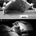
We have explored several approaches [33] to implement model-registered electromagnetic tracking, assisted by commercial developments and collaborations [34] that now provide both good registration of 3D models to the anatomy in situ and the instrument locations. Key elements of the technical capabilities include very small (~1.0 mm) electromagnetic sensors attached to instruments, and “flat plate” electromagnetic transmitter systems [Ascension Technologies Corp, Burlington, VT, USA] which have a large working volume (sufficient to cover the upper abdomen) and excellent immunity to electromagnetic interference.
Calibration
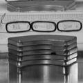
A calibration procedure must be performed to determine the location of the endoscopic and laparoscopic ultrasound plane in space in relation to the tracking sensor attached to the probe [35]. A precise calibration can be best obtained by scanning a phantom with a known geometry. The features are identified in the ultrasound image of the phantom and these features are also located in physical space. The spatial relationship between the two data sets is computed in the calibration process. Some of the commonly used phantoms for US probe calibration are listed below:
Single point target and cross–wire phantoms: The single point target phantom generally consists of a bead or a pinhead. The cross-wire phantom is based on imaging the intersection of two cross wires. The point target or wire crossing is aligned in the image plane and is imaged from multiple viewing angles. A method referred to as plane mapping requires no phantom. This method simply images the tip of a tracked pointer, which can freely move around within a coupling medium while the probe is fixed.
Multiple point targets and cross–wire phantoms: Multiple cross-wire techniques are derived from the single cross-wire phantom. These phantoms are composed of more than one wire crossing that again requires the alignment of one or more of the crossings in the image. The ultrasound images of these phantoms consist of points (cross wire) and/or lines.
Related posts:


Stay updated, free articles. Join our Telegram channel

Full access? Get Clinical Tree


