(1)
Symbow Medical Technology Co., Ltd., Beijing, China
(2)
National Center for Image Guided Therapy, Department of Radiology, Brigham and Women’s Hospital, Harvard Medical School, Boston, MA, USA
Abstract
In image-guided therapy, both medical imaging and device-tracking systems are key components in providing the spatial relationship of a patient and surgical or interventional tools for accurate targeting. Both medical imagers and device-tracking systems need to be integrated and be used for different clinical applications. There are many medical imaging modalities available. Different imaging modality has its unique features in providing anatomical or functional imaging information for a particular application. Different device-tracking method also has its own advantages and weaknesses. In this chapter, different imaging modalities that can be used for procedure guidance are introduced, and their distinctive features on image guidance are discussed. Different device-tracking techniques and their characteristics for image guidance integration are described. The principle of navigation by integrating an imaging modality and a device-tracking modality is then explained. In the end, a few typical combinations of the imaging modality and device-tracking integrated navigation are discussed.
Introduction
Image-guided navigation is very important in surgical procedures when a target cannot been seen directly by naked eyes. These procedures can be open surgical operations or minimally invasive therapeutic procedures such as needle-based percutaneous biopsy and ablations.
During such procedures, medical images in either 2D or 3D mode are used for doctors to determine safe targeting routes and treatment boundaries based on lesion sizes. Many imaging technologies are available for navigation purposes, such as digital radiography (DR), digital subtraction angiography (DSA), ultrasound (US), computed tomography (CT), magnetic resonance imaging (MRI), endoscopy, laparoscopy, and microscopy. Different technology, however, has unique features and suitabality for particular clinical applications, or in some cases, multiple imaging modalities can provide better perception than a single modality alone. Medical images can be acquired prior to a surgical procedure, which is suitable when the procedure room is a different room from the imaging room; in this case, images can be acquired on a different day from the operation day. In this case, due to body position changes or biological motions such as respiration, actual anatomical information during a procedure may be different from that seen when it was acquired. In other cases, procedures can be performed in the same medical imaging room so that images can be acquired more frequently and can best represent the actual anatomical structures in present reality.
Many interventional procedures are nowadays performed with the assistance of medical imaging alone. During a procedure, doctors normally determine the surgical tool’s entry point and targeting trajectory based on doctors’ “spatial imagination” according to the medical images. The spatial information of interventional tools in relevance to the human anatomical structure cannot be properly shown in the medical images, especially before the tools are introduced into the body, when the tools cannot even be seen by many imaging modalities. As a result, such image-guided procedures still strongly depends on the experience of medical doctors and could be inaccurate and subject to safety issues.
Device-tracking systems can track positions of medical devices and obtain their spatial relationship with medical images showing anatomical structures. After proper registration, both medical images and the device position information can be integrated into one coordinate and shown in the same display window. This information can be displayed in either 2D or reconstructed 3D format. Because of the clear visualization of both human anatomical structures (including the target and adjacent critical organs or tissues) and the spatial positioning of the interventional tools, doctors can easily and accurately determine a tools’ entry point and targeting trajectory. The accuracy is assured through the step-by-step visual feedback until the exact target position is reached. The goal of the navigation, however, is accurate, fast, and convenient.
Medical Imaging Technologies
Because medical imaging is a technique that can be used to obtain images representing human anatomical structures or functions, it is critical for diagnosis because, in most cases, the human eyes cannot see through a human body. Nowadays, one trend is to let the imaging modality go beyond diagnosis to the field of treatment. Many medical imaging modalities can see through a human body or through a small opening.
Several imaging modalities still rely on visible light but have unique features that can complement human eyes’ limitations such as microscope and endoscopy.
Most imaging modalities use “invisible light” or energy that is not within the spectra of visual visibility. Such systems can “see through” a human body and obtain information beyond structures. Using special technologies, these systems can also obtain functional images, which are valuable for both diagnosis and treatment guidance. Some typical “invisible light” imaging modalities that can be used for image-guided therapy including radiation-based radiography systems such as X-ray fluoroscopy, CT, and other energy-based modalities such as US, MRI, and positron emission tomography (PET).
Microscopy
Optical (or light) microscope can magnify what is viewed using one or several lenses. Images can be viewed directly through the eyes or on screen in the case of a digital microscope. Due to the nature of the visible light and the almost loss-less optical magnification, microscopy has very high spatial and temporal resolutions and can show fine details of what is viewed. Microscopy has broad clinical applications especially in neurosurgery. The main limitation of optical microscopy, however, is the lack of penetration of the visible light into solid or opaque tissue structures. Also what is viewed is still the structural information that is based on color, shape, or patterns, which may not be able to differentiate lesion targets and adjacent tissues clearly. To compensate for this, during neurosurgery, a digital microscope can be integrated with a device-tracking system to obtain an overlay of both real and virtual reality images reconstructed from CT or MR images so that a surgeon can better judge the target.
Endoscopy
As a microscope, an endoscope uses optical light and lenses for magnification and has high spatial (a few hundred microns) and temporal resolutions (30–70 frames per second). In addition, endoscopes can view beneath the human surface. With the help of flexible optical cables, an endoscope can obtain critical information inside a human body (e.g., inner surfaces and lumen of cavities) through small openings. Due to the minimally invasive nature of endoscopy, it also has very broad clinical applications. Nowadays, close to 30 % of all open surgical procedures are performed with the help of endoscopy in order to minimize invasion and to obtain more visual information. Same as all visible light instruments, endoscopy is limited by visual light penetration. As a result, with the help of a navigation system, images acquired from other invisible light equipment, such as CT or MRI, can be reconstructed and registered with an endoscopic visual image and displayed as overlaid images. The anatomical or functional information from the invisible light images can greatly enhance endoscopic imaging information and help surgeons to better judge the target.
X-Ray Fluoroscopy
X-ray radiation, which has a much shorter wavelength (0.01–10 nm) than that of visible light, also has higher energy and, as such, can penetrate bone and soft tissues. Variation of X-ray absorption and scattering by tissues of differing structural and material densities results in 2D projection images. With the help of fast flat-panel semiconductor detectors, digital fluoroscopic images can be acquired at high spatial resolution in real time (>30 Hz). Radiopaque contrast agents are often used in X-ray fluoroscopy to delineate cavities or vessel lumen.
Due to the 2D projection nature of X-ray fluoroscopy, fine tissue structure may be disguised, tissue boundaries can be indistinct, and image contrast is also limited. During interventional procedures, for example, in angiography, doctors have to apply contrast agents to obtain better differentiation of targets of interest. For certain applications, e.g., spine intervention, two or more projections from different angles are used to get more spatial localization information. In the extreme case such as in the case of a cone-beam volume CT, a full rotation would generate a true 3D volume dataset. No matter whether it is in 2D or 3D formats, X-ray fluoroscopy’s major drawback is its ionizing radiation that can be harmful to both patients and doctors, especially when multiple acquisitions are required, which is very common in most interventional procedures.
X-ray fluoroscopy can be used for both intravascular intervention and percutaneous intervention. For intravascular intervention, X-ray fluoroscopy is probably the only practical approach for now. It has been widely used for vascular diagnosis, implantation, and ablations. For bone-related operations, X-ray fluoroscopy is also commonly used due to its good bone contrast. In both cases, device-tracking systems can be used to track the locations of interventional tools, e.g., a probe or intravascular tubing, in relation to human anatomical structures.
Computed Tomography
CT is an X-ray-based imaging modality that has similar principles to X-ray fluoroscopy in terms of energy sources, radiation, and tissue penetration, except that CT obtains tomographic data. Using filtered back projection or iterative reconstruction techniques, a CT scanner can acquire multiple thin slices (can be of submillimeter in slice thickness for a spiral CT) of the cross-section of a human body in a short period of time. Images are much sharper compared to that of X-ray fluoroscopy. Fine details of tissue structures and sharp edges can be easily distinguished. Contrast agents can be used as in the case of X-ray fluoroscopy to enhance the target of interest or to show metabolic functional information. Even though CT is ideal for bone imaging, it can also be practically used for clinical imaging of many body parts. After reformatting, oblique views can be obtained using a computer from a set of continuously acquired high-resolution thin-slice CT images.
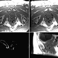
CT has been used commonly for percutaneous interventions, such as biopsy and thermal-based ablations. Due to the tremendous amount of radiation doses emitted by a CT over the course of an interventional procedure, interventional operations and imaging procedures are normally performed in a different time frame, even though CT fluoroscopy is occasionally used in some difficult situations. During most CT-guided interventional procedures, medical personnel leave a CT scan room for imaging and re-enter the CT scan room for procedures immediately after imaging. Independent imaging and operation may introduce guidance mismatch due to patient motion. Another major limitation of CT-guided intervention is the limited image contrast due to its single density-based imaging principle. For certain lesions, e.g., some tumors, the boundaries cannot be clearly distinguished by CT compared to imaging modalities such as MRI.
To pinpoint a target, a device-tracking device can be helpful. One simple method used by most interventional radiologists is to apply a grid array (a set of parallel metal wires) on the surface of a human body. The bright dots (grid wire locations) on CT images will help doctors to get a sense of the spatial relationship of the target and entry points. Stereotactic frames with angle scales are also used for interventional tool guidance. Recently more advanced techniques such as optical and electromagnetic navigation systems are used for accurate CT interventional guidance.
Magnetic Resonance Imaging
MRI is based on the nuclear magnetic resonance of nuclei. To create spatially encoded nucleus excitation, the major physical environment requires a high static magnetic field (0.2–3 T for clinical systems), a three-dimensional gradient magnetic field (from 10 mT/m to a few hundred mT/m), and excitation radiofrequency (RF) waves. The energy emitted from the excited resonant nuclei is picked up by a receiving RF coil and is then amplified. After a series of digitization, reconstruction, and data procession, images can be produced and displayed. Since the gradient can be created in three dimensions, MRI is a true 3D volumetric imaging device with the capability of oblique slicing of any orientation. For clinical imaging, many human nuclei types are paramagnetic materials and can generate MR signals. The most abundant atoms in soft tissues are protons that function as an ideal substrate for clinical imaging.
Compared to other imaging modalities, MRI can probably present the best soft tissue contrasts owing to its unique and multiple contrast mechanisms. Many intrinsic features of the nucleus can function as image contrasts, including nucleus density, longitudinal relaxation time (T1), transverse relaxation time (T2), velocity, perfusion, diffusion, contrast enhancement, and many more. In additional to morphological imaging, MRI can also produce fabulous functional and molecular-level images. With the advance of modern technologies, MR images can be of high spatial and temporal resolutions. With gating or fast data acquisition technologies, moving parts, such as the heart, can be clearly imaged. With such rich information in 3D space and over time with an absence of any ionizing radiation, MRI is one of the ideal devices for treatment guidance.
With the help of tracking markers, surgical navigation can be performed based on presurgical MR images. During a surgery, registration is made based on markers (or anatomical features) and their appearance in MR images. Once registered, a navigation system can therefore track device positions and show their relationship with the target in real time. Such off-line-type navigation is feasible for rigid body parts, such as the neural system and the bones. For rigid body part navigation, distortion from tissue shifts (e.g., brain shift due to brain pressure changes) and motion could compromise navigation accuracy. Tissue resection cannot be updated in off-line navigation mode as well.
With the advance of electromagnetic compatibility technologies, navigation and surgical devices can function normally under an MRI environment. Intraoperative MRI guidance is therefore possible. During such a procedure, MR images are updated continuously with the introduction of surgical or interventional devices into the body. Real-time guidance with continuous updating of what is happening is one of the most accurate navigation approaches. Real-time guidance requires large MRI imaging open space and is normally done in open-bore MRI systems that enable patient access during scanning. Most open-bore MRI systems are made from permanent magnets, whose static fields are normally low (under 0.5 T). Recently, high-field superconducting open MRI systems up to 1.2 T are available commercially, but their costs are high.
Most clinical superconducting high-field MRI systems have a closed-bore configuration. In such a setup, scans and operations have to be off-line, i.e., in different time points. A patient table moves in and out of a magnet bore for imaging and operations. This takes more time and is subject to patient motion causing image mismatch to the patient body. Special care needs to be taken for a patient to keep the same position as that held in the scan.
The major drawback of MRI in therapeutic guidance is its strong magnetic fields and its sensitivity to electrical signal interferences. Special care has to be taken for surgical or interventional devices and navigation systems to work physically within an MRI suite, i.e., the devices have to be made of nonmagnetic materials, and electrical devices have to be electromagnetically shielded so that no mutual signal interference occurs on devices and the MRI system while both are functioning. Thus, the total cost of an MRI-guided intervention can be higher than one without MRI. MRI acquisition speed is also not as fast as that of X-ray-based imaging modalities, such as CT.
Ultrasound
Ultrasound imaging is based on the feature that ultrasound waves reflect back on tissue boundaries. Through piezoelectric transducer, ultrasonic waves can be transmitted and received at different focal points. After analyzing the signals generated from tissue boundary reflections, a slice of anatomical image can be reconstructed and displayed. The acoustic ultrasonic waves are normally in the range of 2–18 MHz, with a trade-off between penetration depth and spatial resolution. Ultrasound can be used to visualize subcutaneous body structures including muscles, tendons, vessels, and internal organs. Due to its characteristics of ease of use, portability, high safety, relative low cost, and scanning environment independence, ultrasound systems have been broadly used in clinical diagnosis and in interventions.
By assembling multiple 2D images, 3D volume images can be obtained as well. The acquisition time of an ultrasound system depends on its phased array size, scanning area, and resolution and is determined by the velocity of the sound in tissue (roughly 1,540 m/s). Even though the travel velocity of ultrasound is much slower than that of X-ray, ultrasound systems can still produce practical “real-time” 2D body images for various interventions.
With a simple probe-attached support frame, ultrasound can be used for interventional guidance such as biopsy or ablations. Using such a frame, an interventional instrument is limited in plane with the ultrasound plane. The reflected signals from the instrument’s front and back edges produce an instrument presence in the ultrasound image. The frame does not support interventional procedures when an instrument is not in plane with the ultrasound plane.
One major limitation of ultrasound imaging is its relatively poorer image tissue contrast compared to that of CT or MRI. Some targeted lesions, especially the boundary of a lesion may be blurry or even missing. The instrument presence in the ultrasound image can also be quite vague.
To compensate for the navigation limitation and the image contrast problem, a device-tracking navigation system can be used. In ultrasonic navigation, the device-tracking technology serves two purposes. First, it helps to co-register the position of a device to that of the ultrasound image (which represents the actual body structure), so that the relative positions of the device versus the target can be visualized spatially no matter whether the device is in plane or off plane with the ultrasound image. The other reason to use a navigation system is to co-register pre-procedure CT or MRI volume images with ultrasound images. In this case, ultrasound provides real-time updates of the anatomy, while CT or MR images are fused with the ultrasound image to enhance its image contrast with better lesion boundaries for accurate interventional treatment.
Positron Emission Tomography
PET systems can detect metabolic functions and thus are important complementary equipment to anatomic imaging devices such as CT. Radiotracers, such as fluorodeoxyglucose (FDG) that is commonly used in clinical applications, concentrate in metabolic active tissues through regional glucose uptakes. The radioisotope decays and emits a positron that annihilates a local electron, producing a pair of gamma photons. The gamma photons trigger the scintillator detector that creates a burst of light. The light is detected by either photomultiplier tubes (PMT) or avalanche photodiodes (APD) and then convert to analog electrical signal. The signal is thereafter digitalized, processed, and shown as images in 3D space.
Metabolic activity images show lesion positions especially in cancer metastasis and, therefore, are very useful for interventional targeting. PET scans, however, are low in spatial resolution. As a result, PET images are normally fused with CT or MR images to present both anatomic and functional information for accurate targeting. Both PET-CT and PET-MRI systems are available clinically. Navigation systems can be integrated with PET-CT or PET-MRI systems to co-register medical images and tracked devices in one coordinate for accurate targeting.
Other Imaging Modalities
Other imaging modalities can be used for image-guided therapy, such as mammography, optical diffusion tomography, and fluorescence tomography. As long as an imaging modality can provide spatial and/or temporal imaging information of the target and adjacent tissue/organs, there is a possibility to use such equipment for surgical or interventional guidance. Different imaging modalities vary in tissue contrasts, spatial and temporal resolutions, ease of use, cost, safety, and applicable clinical applications. One trend is to use multiple imaging modalities with complementary features for better characterization of a lesion target and adjacent tissues or organs along the path of an intervention.
Tracking Technologies
Medical imaging is the basic requirement in image-guided therapy. However, medical imaging alone is not enough to ensure accurate targeting. For example, it may not be able to clearly present the spatial relationship among a target, the physical human body surface, and surgical/interventional devices.
To solve the problem, fiducials can be attached to the surface area that is close to the target. The fiducials can be seen by the surgeon and distinguished in medical images. For example, in the case of CT-guided intervention, metal wire grids can be used as fiducials. With the assistance of fiducials, a doctor can determine intervention entry points on the human body surface and can get a sense of the relative position of a target to the entry points. This, however, in most cases cannot tell the spatial relationship of a surgical or interventional device and the target. The only exception would be when the device has already been placed into a human body and is within the image field of view. Even in such a case, due to various reasons, the device may not be accurately and clearly viewed in medical images. When an interventional device is not in plane with the original scan plane, it is hard to find the device’s tip position even after volume reconstruction and reformatting (especially for 2D imaging with thick slice or with gaps). Many devices may present artifacts in medical images and can obscure true device locations.
To get the true spatial information of a device (such as a biopsy needle), device-tracking systems can be used. A tracking system can follow the movement of a surgical or interventional device and can co-register the device’s spatial information with the space of medical images (body). The integrated information is shown in one display on a monitor in either 2D or 3D views. With the assistance of such a device, targeting accuracy could reach 1–2 mm even considering the overall system errors.
In earlier days, stereotactic frames with angular scales in multiple orientations were used to guide device targeting. Such a mechanical solution is simple and low cost but can be cumbersome and inflexible. The accuracy is also limited. Currently, the device-tracking techniques primarily available are electromagnetic and optically-based.
Electromagnetic Tracking
Electromagnetic fields can be spatially distributed with high resolution. In electromagnetic tracking, an electromagnetic field-generating base (Field Generator or FG as shown in Fig. 18.1a) produces oscillating low-frequency magnetic fields in 3D space. A small radiofrequency (RF) coil (Fig. 18.1b) functioning as a magnetic field detector (Field Detector or FD, also called a sensor) picks up the field strength. The RF signal is then converted to data representing the coil’s relative spatial position and orientation relative to the base. Sensors can be in 5 DOF (degrees of freedom) or 6 DOF where rotational angles can be detected. Due to the fast travel speed of electromagnetic waves, the tracking is in real time (>30 Hz). A tracking system can simultaneously detect several sensors (normally up to 10 for 5 DOF sensors and up to 5 for 6 DOF sensors for commercially available systems). Each sensor can be attached to one device to track the device’s position and orientation.
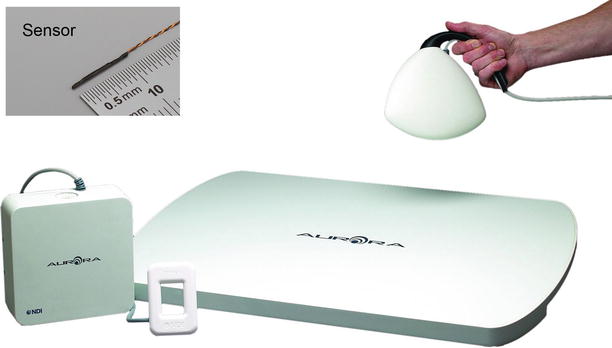
Fig. 18.1
Aurora® electromagnetic tracking system (Northern Digital Inc., Waterloo, Canada) with different types of electromagnetic field-generating bases (Field Generator or FG) which can generate oscillating low-frequency magnetic fields in the 3D space; (Insert) radiofrequency (RF) coil functions as a magnetic field detector (Field Detector or FD, also called a sensor) (Courtesy of Northern Digital Inc., Waterloo, Canada)
FG can fit into a box roughly 20 × 20 × 10 cm in size. The box can be hung on an adjustable arm for field position adjustment. The effective tracking range is roughly 0.5 × 0.5 × 0.5 m. Recently, there is a type of tabletop configuration (less than 4 cm in thickness) that can be placed underneath a patient’s body near the target to generate a field approximately 0.6 m (L) × 0.4 m (W) × 0.6 m (H). With such a setup, the cumbersome supporting arm can be removed to clear more space for physicians to operate.
Electromagnetic tracking technology has several unique features in guidance. First, it does not require line of sight. Body tissues, surgeons’ hands, and drapers may not block the tracking of a device. Secondly, the sensor is very small, which can be easily attached to most surgical tools. A sensor can be as small as 0.3 mm in diameter and less than 10 mm in length. It can even be conveniently placed inside the tip of a biopsy needle and be used to accurately track the exact position of the device tip position.
The major limitation of the electromagnetic tracking technology is its sensitivity to ferromagnetic objects (which can distort the electromagnetic field). Many surgical tools, imager’s patient tables, and monitoring devices bear ferromagnetic objects and can heavily reduce the accuracy and reliability of the tracking. During clinical cases, physicians often have to adjust the FG base position to ensure the sensors can be detected in a particular area. Compared to the optical tracking technology, the measurement volume is normally smaller as well. Another problem for electromagnetic tracking is that the sensor has to be wired, which is inconvenient in lots of clinical situations.
Electromagnetic tracking methods can be used in CT-guided or ultrasound-guided operations, but normally cannot be used in an MRI environment.
Optical Tracking
As the way a human’s two eyes do, two or more CCD cameras (also called sensors) can determine the spatial location of a point under the camera coordinate system by reconstructing the CCD image data if the point is visible to both cameras. The point is defined as a marker in the camera view.
In a CCD image, a marker has to be distinguishable from background in order for the tracking system to automatically identify the position of the marker in the image space. There are two approaches to assist marker detection. One is infrared (IR) light based, and the other is ambient light based.
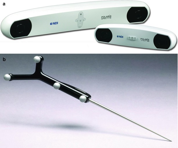
Infrared light-based approaches also have two alternatives. One is active tracking, and the other is passive tracking. In an active tracking system, a marker is wired and actively emits infrared light. In a passive tracking system (Fig. 18.2), a marker (could be a small sphere less than 1 cm in diameter) is specially coated to better reflect infrared light. In this case, the infrared light source (illuminator) in the tracking device emits infrared light, typically located right beside the CCD cameras (Fig. 18.2a). Active tracking is more reliable, but the wiring is inconvenient. Passive tracking is the most commonly used method in clinical practices. Passive tracking may be subject to light interference from background or other reflective objects. The detection accuracy is submillimeter. Obtaining the spatial information of one single point is not enough to get the 6-DOF that is normally needed for tracking a device. In order to do so, at least three markers are needed to form a certain pattern on a frame, called a tracker (Fig. 18.2b). The distances between every two markers are a few centimeters and cannot be the same. The rule of thumb to obtain accurate tracking is that the marker distances are as large as possible and that the distance differences are as large as possible. Of course, large distances make the marker frame too big, which is not convenient. Thus, the size and accuracy have to be balanced. Even though three markers are enough for a tracker, four markers are normally used per tracker in order to improve accuracy and stability and to avoid sight blocking. When tracking multiple tools, several trackers can be used. As long as the tracker patterns (marker distances and angles) differ from each other, the position and orientation of the trackers can be automatically detected and distinguished by the navigation system. For the commercial navigation systems, more than ten trackers can be simultaneously detected. For multiple tracker detection, however, the detection fresh rate may be compromised. For the usual clinical environment where one or two tools are used at the same time, real-time tracking (>30 Hz) is possible.