Anatomy
Year
Reference
Intracranial tumor resection
1993
[4]
Spinal pedicle screw placement
1995
[5]
Hip replacement surgery
1998
[6]
Bronchoscopy
2001
[7]
Craniomaxillofacial surgery
2010
[8]
Heart and coronary arteries
2010
[9]
Ablation of abdominal organs
2010
[10]
Liver surgery
2011
[11]
An early paper by Bucholz et al. described an image-guided navigation system for neurosurgical tumor resections [4]. The system included a head ring with light-emitting diodes tracked by an optical localizer. A custom built forceps with light-emitting diodes built into the handle was also constructed. A clinical trial with 35 patients was completed, with the benefits being shorter hospital stays, a decreased incidence of postoperative neurological deficits, and more aggressive resection of pathology.
Spinal pedicle screw placement was one of the earliest applications for image-guided navigation [5]. Nolte et al. describe an early navigation system based on an Optotrak® tracker (Northern Digital, Inc., Waterloo, Canada), Sun workstation (Sun Microsystems Inc., Santa Clara, CA), and custom software. The concept of a dynamic reference base to enable measurement relative to the local vertebral body was introduced. A cadaver study was done to evaluate the system, which was shown to be highly accurate, and an initial clinical trial of six patients was completed.
Another early orthopedic application was hip replacement surgery [6]. The goal was to improve the accuracy of acetabular alignment during total hip replacement surgery by using an image-guided navigation system. The navigation system consisted of three main components: (1) a preoperative planner, (2) a hip range-of-motion simulator, and (3) an intraoperative tracking and guidance system. The system was integrated into the operating room, and a clinical trial of 10 patients was completed. The difficulty in maintaining the desired alignment when press fitting the acetabular cup could be quantified using the system, with the goal of using this information to improve the accuracy of placement.
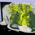
Bronchoscopy involves the visualization of the airways for diagnostics and therapeutic purposes. In particular, transbronchial needle aspiration is a minimally invasive approach to sample the tissue in the lymph nodes behind the airway walls. Image-guided bronchoscopy based on CT images was described in an early paper by a team at Pennsylvania State University [7]. The airway tree was segmented using an adaptive searching technique and guidance paths were created the centerlines of the major airways. Both animal and human studies were completed.
The use of image-guided navigation in craniomaxillofacial surgery is described in an overview article [8]. The major applications have been in orbital trauma and reconstruction, as well as in tumor surgery, particularly that of the skull base. The imaging modality is almost exclusively CT, and in particular cone-beam CT is well suited to craniomaxillofacial surgery. The workflow of data acquisition, segmentation, and treatment plan is described. Several clinical examples are given, and the author notes the value of image-guided navigation in providing consistent results in the operating room.
Image-guided navigation within the heart and cardiovascular system is reviewed by Beyar et al. [9]. In particular, the field of interventional cardiology is described and the navigation of catheters within the arteries. The concepts of image-guided navigation have been extended in this domain to incorporate remote control systems such as the Stereotaxis Magnetic Navigation System (Stereotaxis, Inc., St. Louis, MO), where the catheter is pulled through the body using externally manipulated magnetic fields and the physician controls the system through a joystick interface and visual display. Electromagnetic mapping of cardiac electrical activity is also incorporated to aid in precisely carrying out cardiac ablation procedures.
One current research thrust in image-guided navigation is to move towards soft tissue applications, including abdominal organs such as the liver. The use of navigation for ablation in the field of interventional oncology is described by Wood et al. [10]. These navigation systems are based on electromagnetic tracking, which do not require a line-of-sight, and can track instruments inside the body. A workflow for CT and ultrasound-guided biopsy in the liver is given, and the fusion of multiple imaging modalities including PET and CT is described. The use of overlapping ablations to cover the entire tumor plus some margin is also presented.
Related work for soft tissue applications includes the use of nonrigid registration for organs such as the liver [11]. These techniques have been implemented in a commercial image-guided navigation system for open hepatic surgery from Pathfinder Therapeutics (Nashville, TN). The system incorporates a laser range scanner (RealScan 200C, 3-D Digital Corporation, Bethel, CT) to generate a surface map of the liver. Data was collected from 12 clinical liver cases at a single site, and the surface displacements found were in the range of 0.5–2.0 cm. A multicenter clinical trial is ongoing to investigate the value of these techniques in improving the precision in liver tumor resection and ablation.
In summary, image-guided navigation has moved from early applications focusing on bony landmarks such as cranial tumor resection, spinal pedicle screw placement, hip replacement surgery, and craniofacial reconstruction to vessel-based applications such as bronchoscopy and interventional cardiology and to soft tissue abdominal applications such as liver biopsy and ablation. In the next sections, we will describe a typical workflow for image-guided navigation and then discuss some of the component technologies.
Image-Guided Navigation Workflow and Component Technologies
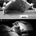
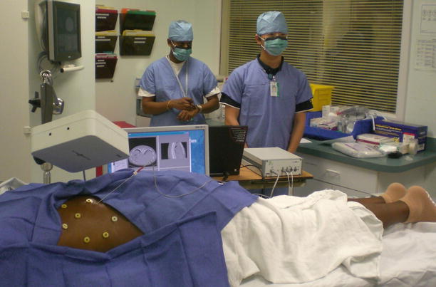
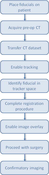
Over the past decade, our research team has developed several systems for image-guided navigation, focused on minimally invasive abdominal interventions such as percutaneous needle biopsy. This system was recently used in a clinical trial for CT-guided lung biopsy at Georgetown University Medical Center as shown in Fig. 6.1. The system workflow is as follows:
1.
Place fiducials on patient
2.
Obtain a CT image
3.
Transfer the CT image to the image-guided workstation using the DICOM protocol
4.
Enable the electromagnetic tracking system
5.
Identify fiducials points in CT space and electromagnetic tracker space
6.
Paired-point registration
7.
Virtual image overlay and navigation by the physician
Fig. 6.1
Clinical trial of electromagnetically tracked lung biopsy in the CT suite at Georgetown University Hospital (Courtesy of Filip Banovac, MD)
Fig. 6.2
Typical workflow for an image-guided navigation system
The system is built on several key components, which will be described in the following sections:
Preoperative imaging
Electromagnetic tracking
Registration techniques
Visualization to display the anatomy
A software framework to tie everything together
These components are typical of image-guided navigation systems and will be described in the following sections. Some sections will be shorter than others, and the reader is referred to the following chapters for further details:
Imaging
Many different imaging modalities have been used for image-guided navigation, including ultrasound, x-ray imaging such as fluoroscopy and computed tomography (CT), and magnetic resonance imaging (MRI). Most image-guided navigation systems, particularly those systems that have been commercialized by the major vendors, rely on preoperative tomographic imaging such as CT or MRI. Tomographic imaging can provide an exquisite three-dimensional map of the anatomy, and these images can be displayed to the physician as described in the visualization section below.
While most image-guided navigation systems are based on preoperative imaging, there is an increasing interest in using intraoperative imaging for navigation. One trend in this direction has been the development of cone-beam CT imaging (CBCT), which provides CT-like capabilities using a fluoroscopy system. A fluoroscopy system consists of an x-ray source and detector, which are placed on opposite sides of a patient, and provides projection images of the patient. By rotating the C-arm on which the source and detector are mounted, multiple projections from different angles can be obtained and used to reconstruct a tomographic data set. CBCT has become a mainstay of many interventional suites, and commercial vendors such as Philips and Siemens have introduced navigation systems based on this technology. CBCT can also be used with mobile C-arms that can be brought into the operating room to provide navigation for surgical procedures. This concept was pioneered by Medtronic Inc., (Minneapolis, MN) with the O-arm system, which consists of a CBCT and associated navigation hardware and software [12].
In the future, we can expect to see more use of multiple imaging modalities and image fusion to aid in navigation. This trend is already seen in the clinical environment with the widespread acceptance of PET-CT imaging, which combines positron emission tomography (PET) with CT imaging. The main application area of PET-CT has been in oncology, and it has also been incorporated in image-guided navigation for that purpose. A group in Austria recently reported on a system for image-guided navigation in head and neck cancer using PET-CT image fusion [13]. A study of 6 patients found an unsafe resection margin in 4 of the patients, and additional image-guided resection allowed local control of the tumor to be achieved in 3 patients.
Tracking
Tracking devices are an essential component of any image-guided navigation system. Their primary function is to track the position of instruments relative to patient anatomy. Improvements in sophistication and accuracy of tracking systems in the last 10 years have been critical to the development of image-guided systems. The earliest tracking systems used were mechanical digitizers. While highly accurate, their main limitation was the large physical footprint and cumbersome use in an operating environment. Addressing this concern, optical tracking systems with high measurement accuracy and large field of view found quick adoption in the early image-guided navigation space. However, optical tracking systems require that a line-of-sight be maintained between the tracking device and instrument to be tracked. This is not always convenient and furthermore precludes tracking of flexible instruments inside the body. This challenge led to the development of electromagnetic tracking systems, which have no line-of-sight requirement and are able to track instruments such as catheters and the tips of needles inside the body.
Today, the choice of what tracking system to incorporate within an IGT solution is application dependent and variant on factors such as cost, desired work volume, and clinical accuracy constraints. Table 6.2 provides a list of tracking systems. We then give a brief synopsis of the different technologies in use: (a) optical videometric, (b) optical active and passive infrared, and (c) electromagnetic.
Table 6.2
Tracking systems in use today for image-guided navigation
Technology | Product | Company |
|---|---|---|
Optical videometric
Related posts:Stay updated, free articles. Join our Telegram channel
Full access? Get Clinical Tree
 Get Clinical Tree app for offline access

|