Nuclear Imaging—The Gamma Camera
Nuclear imaging produces images of the distributions of radionuclides in patients. Because charged particles from radioactivity in a patient are almost entirely absorbed within the patient, nuclear imaging uses γ-rays, characteristic x-rays (usually from radionuclides that decay by electron capture), or annihilation photons (from positron-emitting radionuclides) to form images.
To form a projection image, an imaging system must determine not only the photon flux density (number of x- or γ-rays per unit area) at each point in the image plane but also the directions of the detected photons. In x-ray transmission imaging, the primary photons travel known paths diverging radially from a point (the focal spot of the x-ray tube). In contrast, the x- or γ-rays from the radionuclide in each volume element of a patient are emitted isotropically (equally in all directions). Nuclear medicine instruments designed to image x- and γ-ray-emitting radionuclides (gamma cameras) use collimators that permit photons following certain trajectories to reach the detector but absorb most of the rest. A heavy price is paid for using collimation—the vast majority (typically well over 99.95%) of emitted photons is wasted. Thus, collimation, although necessary for the formation of projection images, severely limits the performance of these devices. Instruments for imaging positron (β+)-emitting radionuclides can avoid collimation by exploiting the unique properties of annihilation radiation to determine the directions of the photons. Positron-emission nuclear imaging devices are discussed in Chapter 19.
The earliest widely successful nuclear medicine imaging device, the rectilinear scanner, which dominated nuclear imaging from the early 1950s through the late 1960s, used a moving radiation detector to sample the photon fluence at a small region of the image plane at a time.1 This was improved upon by the use of a largearea position-sensitive detector (a detector indicating the location of each interaction) to sample simultaneously the photon fluence over the entire image plane. The Anger scintillation gamma camera, which currently dominates single-photon x- and γ-ray nuclear imaging, is an example of the latter method. The scanning detector system is less expensive, but the position-sensitive detector system permits more rapid image acquisition and has replaced single scanning detector systems.
Gamma cameras using gas-filled detectors (such as multiwire proportional counters) have been developed in the past. Unfortunately, the low densities of gases, even when pressurized, yield low detection efficiencies for the x- and γ-ray energies commonly used in single-photon nuclear imaging. To obtain a sufficient number of interactions to form statistically valid images without imparting an excessive radiation dose to the patient, nearly all gamma cameras in routine clinical use utilize solid inorganic scintillators as detectors because of their superior detection efficiency. However, gamma cameras using semiconductor detectors have been developed. These devices utilize high atomic number, high-density semiconductor material of sufficient
thickness for absorbing the x- and γ-rays commonly used in nuclear imaging, and that can be operated at room temperature. The leading detector material in use to date is cadmium zinc telluride (CZT). Both small and large field of view (FOV) cameras using CZT semiconductor detectors are now commercially available.
thickness for absorbing the x- and γ-rays commonly used in nuclear imaging, and that can be operated at room temperature. The leading detector material in use to date is cadmium zinc telluride (CZT). Both small and large field of view (FOV) cameras using CZT semiconductor detectors are now commercially available.
The attenuation of x-rays in the patient is useful in radiography, fluoroscopy, and x-ray computed tomography and, in fact, is necessary for image formation. However, in nuclear imaging, attenuation is usually a hindrance; it causes a loss of information and, especially when it is very non-uniform, it is a source of artifacts.
The quality of a nuclear medicine image is determined not only by the performance of the nuclear imaging device but also by the properties of the radiopharmaceutical used. For example, the degree to which a radiopharmaceutical preferentially accumulates in a lesion of interest largely determines the smallest such lesion that can be detected. Furthermore, the dosimetric properties of a radiopharmaceutical determine the maximal activity that can be administered to a patient, which in turn affects the amount of statistical noise (quantum mottle) in the image. For example, in the 1950s and 1960s, radiopharmaceuticals labeled with I-131 and Hg-203 were commonly used. The long half-lives of these radionuclides and their beta particle emissions limited administered activities to approximately 150 microcuries (µCi). These low administered activities and the high-energy γ-rays of these radionuclides resulted in high statistical noise images and required the use of collimators providing poor spatial resolution. Many modern radiopharmaceuticals are labeled with technetium-99m (Tc-99m), whose short half-life (6.01 h) and isomeric transition decay (˜88% of the energy is emitted as 140-keV γ-rays; only ˜12% is given to conversion electrons and other emissions unlikely to escape the patient) permit activities of up to about 35 millicuries (mCi) to be administered. The high γ-ray flux from such an activity permits the use of high-resolution (low-efficiency) collimators. Radiopharmaceuticals are discussed in Chapter 16.
18.1 PLANAR NUCLEAR IMAGING: THE ANGER SCINTILLATION CAMERA
The Anger scintillation gamma camera, developed by Hal O. Anger at the Donner Laboratory in Berkeley, California, in the 1950s, is by far the most common nuclear medicine imaging device.2 However, it did not begin to replace the rectilinear scanner significantly until the late 1960s, when its spatial resolution became comparable to that of the rectilinear scanner and Tc-99m-labeled radiopharmaceuticals, for which it is ideally suited, became commonly used in nuclear medicine. Most of the advantages of the scintillation camera over the rectilinear scanner stem from its ability simultaneously to collect data over a large area of the patient, rather than one small area at a time. This permits the more rapid acquisition of images and enables dynamic studies that depict the redistribution of radionuclides to be performed. Because the scintillation camera wastes fewer x- or γ-rays than earlier imaging devices, its images have less quantum mottle (statistical noise) and it can be used with higher resolution collimators, thereby producing images of better spatial resolution. The scintillation camera is also more flexible in its positioning, permitting images to be obtained from almost any angle. Although it can produce satisfactory images using x- or γ-rays ranging in energy from about 70 keV (Tl-201) to 364 keV (I-131) or perhaps even 511 keV (F-18), the scintillation camera is best suited for imaging photons with energies in the range of 100 to 200 keV. Figure 18-1 shows a modern scintillation camera.
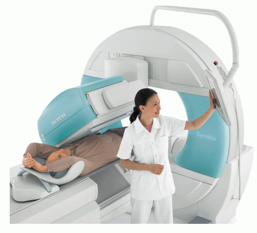 ▪ FIGURE 18-1 Modern dual rectangular head scintillation camera. The two heads are in a 90° orientation for cardiac SPECT imaging (discussed in Chapter 19). (© Siemens Healthineers 2019. Used with permission.) |
Gamma cameras of other designs have been devised (briefly described later in this chapter) and have recently achieved commercial success. However, the overall superior cost-effectiveness, versatility and performance of the Anger camera across the entire spectrum of clinical (including tomographic) applications have caused it to remain dominant in nuclear imaging. The term scintillation camera will refer exclusively to the Anger scintillation camera throughout this chapter.
18.1.1 Design and Principles of Operation
Detector and Electronic Circuits
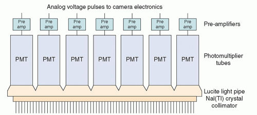
A scintillation camera head (Fig. 18-2) contains a disk-shaped (mostly on older cameras) or rectangular thallium-activated sodium iodide [NaI(Tl)] crystal, typically 0.95 cm (3/8 inch) thick, optically coupled to a large number (typically 37 to 91) of 5.1- to 7.6-cm (2- to 3-inch) diameter photomultiplier tubes (PMTs). PMTs and NaI(Tl) scintillation crystals were described in Chapter 17. The NaI(Tl) crystals of modern cameras have large areas; the rectangular crystals of one manufacturer are 59 × 44.5 cm (23 × 17.4 inches), with an FOV of about 53 by 39 cm. Some camera designs incorporate a Lucite light pipe between the glass cover of the crystal and PMTs; in others, the PMTs are directly coupled to the glass cover. In most cameras, a preamplifier is connected to the output of each PMT. Between the patient and the crystal is a collimator, usually made of lead, that only allows x- or γ-rays approaching from certain directions to reach the crystal. The collimator is essential; a scintillation camera without a collimator does not generate meaningful images. Figure 18-2 shows a parallel-hole collimator.
The lead walls, called septa, between the holes in the collimator absorb most photons approaching the collimator from directions that are not aligned with the holes. Most photons approaching the collimator from a nearly perpendicular direction pass through the holes; many of these are absorbed in the sodium iodide crystal, causing the emission of visible light and ultraviolet (UV) radiation. The light and UV photons are converted into electrical signals and amplified by the PMTs. These signals are
further amplified by the preamplifiers (preamps). The amplitude of the electrical pulse produced by each PMT is proportional to the amount of light it received following an x- or γ-ray interaction in the crystal.
further amplified by the preamplifiers (preamps). The amplitude of the electrical pulse produced by each PMT is proportional to the amount of light it received following an x- or γ-ray interaction in the crystal.
Because the collimator septa intercept most photons approaching the camera along paths not aligned with the collimator holes, the pattern of photon interactions in the crystal forms a two-dimensional projection of the three-dimensional activity distribution in the patient. The PMTs closest to each photon interaction in the crystal receive more light than those that are more distant, causing them to produce larger voltage pulses. The relative amplitudes of the pulses from the PMTs following each interaction contain sufficient information to determine the location of the interaction in the plane of the crystal within a few mm.
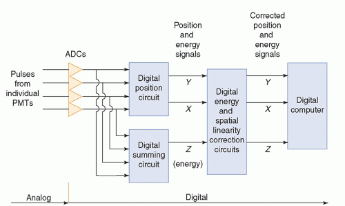
Early scintillation cameras formed images on photographic film using only analog electronic circuitry. In the late 1970s, digital circuitry began to be used for some functions. Modern scintillation cameras have an analog-to-digital converter (ADC) for the signal from the preamp following each PMT (Fig. 18-3). ADCs are described in Chapter 5. The remaining circuits used for signal processing and image formation are digital. The
digitized signals from the preamps are sent to two circuits. The position circuit receives the signals from the individual preamps after each x- or γ-ray interaction in the crystal and, by determining the centroid of these signals, produces an X-position signal and a Y-position signal that together specify the position of the interaction in the plane of the crystal. (This method of determining the position of an interaction is sometimes referred to as “Anger logic.”) The summing circuit adds the signals from the individual preamps to produce an energy (Z) signal proportional in amplitude to the total energy deposited in the crystal by the interaction. These digital signals are then sent to correction circuits, described later in this chapter, to correct position-dependent systematic errors in event position assignment and energy determination (see Spatial Linearity and Uniformity, below). These correction circuits greatly improve the spatial linearity and uniformity of the images. The corrected energy (Z) signal is sent to an energy discrimination circuit. An interaction in the camera’s crystal is recorded as a count in the image only if the energy (Z) signal is within a preset energy window. Scintillation cameras permit as many as four energy windows to be set for imaging radionuclides, such as Ga-67 and In-111, which emit useful photons of more than one energy. Following energy discrimination, the X– and Y-position signals are sent to a digital computer, where they are formed into a digital projection image, as described in Section 18.2 below, that can be displayed on a monitor.
digitized signals from the preamps are sent to two circuits. The position circuit receives the signals from the individual preamps after each x- or γ-ray interaction in the crystal and, by determining the centroid of these signals, produces an X-position signal and a Y-position signal that together specify the position of the interaction in the plane of the crystal. (This method of determining the position of an interaction is sometimes referred to as “Anger logic.”) The summing circuit adds the signals from the individual preamps to produce an energy (Z) signal proportional in amplitude to the total energy deposited in the crystal by the interaction. These digital signals are then sent to correction circuits, described later in this chapter, to correct position-dependent systematic errors in event position assignment and energy determination (see Spatial Linearity and Uniformity, below). These correction circuits greatly improve the spatial linearity and uniformity of the images. The corrected energy (Z) signal is sent to an energy discrimination circuit. An interaction in the camera’s crystal is recorded as a count in the image only if the energy (Z) signal is within a preset energy window. Scintillation cameras permit as many as four energy windows to be set for imaging radionuclides, such as Ga-67 and In-111, which emit useful photons of more than one energy. Following energy discrimination, the X– and Y-position signals are sent to a digital computer, where they are formed into a digital projection image, as described in Section 18.2 below, that can be displayed on a monitor.
Collimators
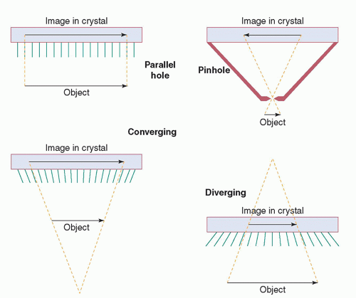
The collimator of a scintillation camera forms the projection image by permitting x- or γ-ray photons approaching the camera from certain directions to reach the crystal while absorbing most of the other photons. Collimators are made of high atomic number, high-density materials, usually lead. The most commonly used collimator is the parallel-hole collimator, which contains thousands of parallel holes (Fig. 18-4). The holes may be round, square, or triangular; however, most
state-of-the-art collimators have hexagonal holes and are usually made from lead foil, although some are cast. The partitions between the holes are called septa. The septa must be thick enough to absorb most of the photons incident upon them. For this reason, collimators designed for use with radionuclides that emit higher energy photons have thicker septa. There is an inherent compromise between the spatial resolution and efficiency (sensitivity) of collimators. Modifying a collimator to improve its spatial resolution (e.g., by reducing the size of the holes or lengthening the collimator) reduces its efficiency. Most scintillation cameras are provided with a selection of parallel-hole collimators. These may include “low-energy, high-sensitivity”; “low-energy, all-purpose” (LEAP); “low-energy, high-resolution”; “medium-energy” (suitable for Ga-67 and In-111); “high-energy” (for I-131); and “ultra-high-energy” (for F-18) collimators. The size of the image produced by a parallel-hole collimator is not affected by the distance of the object from the collimator. However, its spatial resolution degrades rapidly with increasing collimator-to-object distance. The FOV of a parallel-hole collimator does not change with distance from the collimator.
state-of-the-art collimators have hexagonal holes and are usually made from lead foil, although some are cast. The partitions between the holes are called septa. The septa must be thick enough to absorb most of the photons incident upon them. For this reason, collimators designed for use with radionuclides that emit higher energy photons have thicker septa. There is an inherent compromise between the spatial resolution and efficiency (sensitivity) of collimators. Modifying a collimator to improve its spatial resolution (e.g., by reducing the size of the holes or lengthening the collimator) reduces its efficiency. Most scintillation cameras are provided with a selection of parallel-hole collimators. These may include “low-energy, high-sensitivity”; “low-energy, all-purpose” (LEAP); “low-energy, high-resolution”; “medium-energy” (suitable for Ga-67 and In-111); “high-energy” (for I-131); and “ultra-high-energy” (for F-18) collimators. The size of the image produced by a parallel-hole collimator is not affected by the distance of the object from the collimator. However, its spatial resolution degrades rapidly with increasing collimator-to-object distance. The FOV of a parallel-hole collimator does not change with distance from the collimator.
A pinhole collimator (Fig. 18-4) is commonly used to produce magnified views of small objects, such as the thyroid gland or a hip joint. It consists of a small (typically 3- to 5-mm diameter) hole in a piece of lead or tungsten mounted at the apex of a leaded cone. Its function is identical to the pinhole in a pinhole photographic camera. As shown in the figure, the pinhole collimator produces a magnified image whose orientation is reversed. The magnification of the pinhole collimator decreases as an object is moved away from the pinhole. If an object is as far from the pinhole as the pinhole is from the crystal of the camera, the object is not magnified and, if the object is moved yet farther from the pinhole, it is minified. (Clinical imaging is not performed at these distances.) There are pitfalls in the use of pinhole collimators due to the decreasing magnification with distance. For example, a thyroid nodule deep in the mediastinum can appear to be in the thyroid itself. Pinhole collimators are used extensively in pediatric nuclear medicine. On some pinhole collimators, the part containing the hole can be removed and replaced with a part with a hole of another diameter; this allows the hole size to be varied for different clinical applications.
A converging collimator (Fig. 18-4) has many holes, all aimed at a focal point in front of the camera. As shown in the figure, the converging collimator magnifies the image. The magnification increases as the object is moved away from the collimator. A disadvantage of a converging collimator is that its FOV decreases with distance from the collimator. A diverging collimator (Fig. 18-4) has many holes aimed at a focal point behind the camera. It produces a minified image in which the amount of minification increases as the object is moved away from the camera. A diverging collimator may be used to image a part of a patient using a camera whose FOV, if a parallel-hole collimator were used, would be smaller than the body part to be imaged. For example, a diverging collimator could enable a mobile scintillation camera with a 25- or 30-cm-diameter crystal to perform a lung study of a patient in the intensive care unit. If a diverging collimator is reversed on a camera, it becomes a converging collimator. The diverging collimator is seldom used today, because it has inferior imaging characteristics to the parallel-hole collimator and the large rectangular crystals of most modern cameras render it unnecessary. The converging collimator is also seldom used; its imaging characteristics are superior, in theory, to the parallel-hole collimator, but its decreasing FOV with distance and varying magnification with distance have discouraged its use. However, a hybrid of the parallel-hole and converging collimator, called a fan-beam collimator, may be used in single photon emission computed tomography (SPECT) to take advantage of the favorable imaging properties of the converging collimator (see Chapter 19).
Many special-purpose collimators, such as the seven-pinhole collimator, have been developed. However, most of them have not enjoyed wide acceptance. The performance characteristics of parallel-hole, pinhole, and fan-beam collimators are discussed below (see Performance).
Principles of Image Formation
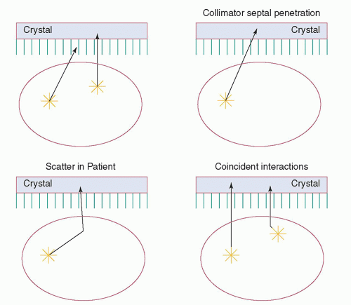
In nuclear imaging, which can also be called emission imaging, the photons from each point in the patient are emitted isotropically. Figure 18-5 shows the fates of the x- and γ-rays emitted in a patient being imaged. Some photons escape the patient without interaction, some scatter within the patient before escaping, and some are absorbed within the patient. Many of the photons escaping the patient are not detected because they are emitted in directions away from the image receptor. The collimator absorbs the vast majority of those photons that reach it. As a result, only a tiny fraction of the emitted photons (about 1 to 2 in 10,000 for typical low-energy parallel-hole collimators) has trajectories permitting passage through the collimator holes; thus, well over 99.9% of the photons reaching the gamma camera during imaging are wasted. Some photons penetrate the septa of the collimator without interaction. Of those reaching the crystal, some are absorbed in the crystal, some scatter from the crystal, and some pass through the crystal without interaction. The relative probabilities of these events depend on the energies of the photons and the thickness of the crystal. Of those photons absorbed in the crystal, some are absorbed by a single photoelectric absorption, whereas others undergo one or more Compton scatters before a photoelectric absorption. It is also possible for two photons to interact simultaneously with an Anger γ crystal; if the energy (Z) signal from the coincident
interactions is within the energy window of the energy discrimination circuit, the result will be a single count mispositioned in the image. The fraction of simultaneous interactions increases with the interaction rate of the camera.
interactions is within the energy window of the energy discrimination circuit, the result will be a single count mispositioned in the image. The fraction of simultaneous interactions increases with the interaction rate of the camera.
Interactions in the crystal of photons that have been scattered in the patient, photons that have penetrated the collimator septa, photons that undergo one or more scatters in the crystal, and coincident interactions in an Anger camera crystal reduce the spatial resolution and image contrast and increase random noise. The function of the camera’s energy discrimination circuits (also known as pulse height analyzers) is to reduce this loss of resolution and contrast by rejecting photons that scatter in the patient or result in coincident interactions. Unfortunately, the limited energy resolution of the camera causes a wide photopeak, and low-energy photons can scatter through large angles with only a small energy loss. For example, a 140-keV photon scattering 45° will only lose 7.4% of its energy. An energy window that encompasses most of the photopeak will unfortunately still accept a significant fraction of the scattered photons and coincident interactions.
It is instructive to compare single photon emission imaging with x-ray transmission imaging (Table 18-1). In x-ray transmission imaging, including radiography and fluoroscopy, an image is projected on the image receptor because the x-rays originate from a very small source that approximates a point. In comparison, the photons in nuclear imaging are emitted isotropically throughout the patient and therefore collimation is necessary to form a projection image. Furthermore, in x-ray transmission imaging, x-rays that have scattered in the patient can be distinguished from primary x-rays by their directions and thus can be largely removed by grids. In emission imaging, primary photons cannot be distinguished from scattered photons by their directions. The collimator removes about the same fraction of scattered photons as it does primary photons and, unlike the grid in x-ray transmission imaging, does not reduce the fraction of counts in the resultant image due to scatter. Scattered photons in nuclear imaging can only be differentiated from primary photons by energy, because scattering reduces photon energy. In emission imaging, energy discrimination is used to reduce the fraction of counts in the image caused by scattered radiation. Finally, nuclear imaging devices must use pulse mode (the signal from each interaction is processed separately) for event localization and so that interaction-by-interaction energy discrimination can be employed; x-ray transmission imaging systems typically produce much larger photon fluxes and so most such systems do not detect, discriminate, and record on a photon-by-photon basis.
18.1.2 Alternative Camera Design—The Multielement Camera
An alternative to the Anger scintillation camera for nuclear medicine imaging is the multi-detector element (also known as pixelated) camera. An image receptor of such
a camera is a two-dimensional array of many small independent detector elements. Such cameras are used with collimators for image formation, as are Anger scintillation cameras.
a camera is a two-dimensional array of many small independent detector elements. Such cameras are used with collimators for image formation, as are Anger scintillation cameras.
TABLE 18-1 COMPARISON OF SINGLE-PHOTON NUCLEAR IMAGING WITH X-RAY TRANSMISSION IMAGING | ||||||||||||
|---|---|---|---|---|---|---|---|---|---|---|---|---|
|
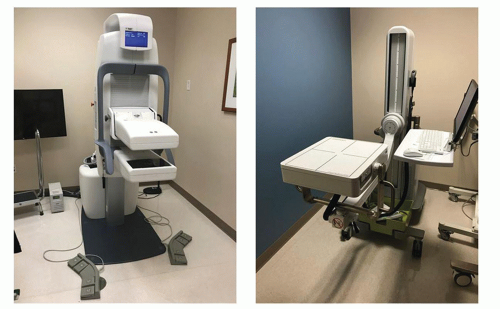
The first such camera to achieve clinical acceptance (albeit limited) in the 1970s and early 1980s consisted of 294 NaI(Tl) scintillation crystals arranged in an array of 14 rows and 21 columns. A clever arrangement of light pipes was used to route the light from the crystals to 35 PMTs, with all crystals in a row connected to one PMT and all crystals in a column being connected to another PMT. Light signals being simultaneously received by the PMT for a column and another PMT for a row identified the crystal in which a x- or γ-ray interaction occurred. Since that time, other multielement cameras have been developed and become commercially available. One scintillatorbased design (indirect conversion to an electrical signal, as is the case for an Anger camera), consists of a 64 × 48 array of 2.96 mm × 2.96 mm × 6 mm thick NaI(Tl) crystals, each 8 × 8 sub-array of which is coupled to an independent position-sensitive PMT, thus not requiring Anger logic for event positioning. Each detector element of another such scintillator-based multielement camera is a 3.3 mm × 3.3 mm × 6 mm thick thallium-activated cesium iodide (CsI[Tl]) crystal optically coupled to a silicon photodiode, in a 120 × 96 array of crystals (Fig. 18-6 right). In a second, so-called directconversion design, each detector element is a CZT semiconductor-based crystal, whereby the interaction of a x- or γ-ray in the crystal produces a current of electrons and holes directly, the total charge of which is proportional to the energy imparted. One such CZT camera is a breast-specific γ imager containing ninety-six 5 mm thick CZT crystals, each pixelated electronically into a 16 × 16 array of 1.6 mm × 1.6 mm detector elements. Two other such cameras from one manufacturer are a dedicated breast imaging (Fig. 18-6) and a large FOV camera, respectively, with 2.46 mm × 2.46 mm × 5 mm thick (750b, 96 × 64 array) or 7.25 mm thick (870, 208 × 160 array) detector elements, manufactured as 39.36 mm × 39.36 mm CZT crystals that are pixelated electronically.
The intrinsic spatial resolution of a multielement detector camera is determined by the physical dimensions of the independent detector elements. One advantage to the multielement camera design is that very high interaction rates can be tolerated with only limited dead-time losses because of the independent detectors in the image
receptor. A second advantage is improved energy resolution afforded by the alternative detector material and method of processing events. A disadvantage is the complexity of the electronics needed to process the signals from such a large number of independent detectors. A limitation of current semiconductor multielement cameras is a maximum imaging x- or γ-ray energy of about 200 keV, due to a restriction on crystal thickness.
receptor. A second advantage is improved energy resolution afforded by the alternative detector material and method of processing events. A disadvantage is the complexity of the electronics needed to process the signals from such a large number of independent detectors. A limitation of current semiconductor multielement cameras is a maximum imaging x- or γ-ray energy of about 200 keV, due to a restriction on crystal thickness.
18.1.3 Performance
Measures of Performance
Measures of the performance of a gamma camera with the collimator attached are called system or extrinsic measurements. Measures of camera performance with the collimator removed are called intrinsic measurements. System measurements give the best indication of clinical performance, but intrinsic measurements are often more useful for comparing the performance of different cameras, because they isolate camera performance from collimator performance.
Uniformity is a measure of a camera’s response to uniform irradiation of the detector surface. The ideal response is a perfectly uniform image. Intrinsic uniformity is usually measured by placing a point radionuclide source (typically 1 mCi of Tc-99m) in front of the uncollimated camera. The source should be placed at least four times the largest dimension of the detector away to ensure uniform irradiation of the camera surface and at least five times that distance away, if the uniformity image is to be analyzed quantitatively using a computer. System uniformity, which reveals collimator as well as camera defects, is assessed by placing a uniform planar radionuclide source in front of the collimated camera. Solid planar sealed sources of Co-57 (typically 5 to 10 mCi when new) and planar sources that may be filled with a Tc-99m solution are commercially available. A planar source should be large enough to cover the entire detector of the camera. The uniformity of the resultant images may be analyzed by a computer or evaluated visually.
Spatial resolution is a measure of a camera’s ability to accurately portray spatial variations in activity concentration and to distinguish as separate radioactive objects in close proximity. The system spatial resolution is evaluated by acquiring an image of a line source, such as a capillary tube filled with Tc-99m, using a computer interfaced to the collimated camera and determining the line spread function (LSF). (System resolution for a multielement gamma camera should be measured at a distance, typically 100 mm, as resolution is essentially the detector element width and height at the collimator face.) The LSF, described in Chapter 4, is a cross-sectional profile of the image of a line source. The full-width-at-half-maximum (FWHM), the full-width-attenth-maximum, and the modulation transfer function (described in Chapter 4) may all be derived from the LSF.
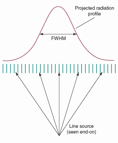
The system spatial resolution, if measured in air so that scatter is not present, is determined by the collimator resolution and the intrinsic resolution of the camera. The collimator resolution is defined as the FWHM of the radiation transmitted through the collimator from a line source (Fig. 18-7). It is not directly measured, but calculated from the system and intrinsic resolutions. The intrinsic resolution of an Anger camera is determined quantitatively by acquiring an image, with a sheet of lead containing one or more thin slits placed against the uncollimated camera, using a point source. (The evaluation of multielement camera intrinsic resolution is not applicable, as it is simply the detector element width and length.) The point source should be positioned at least five times the largest dimension of the camera’s detector away.
The system (RS), collimator (RC), and intrinsic (RI) resolutions, as indicated by the FWHMs of the LSFs, are related by the following equation:
The system (RS), collimator (RC), and intrinsic (RI) resolutions, as indicated by the FWHMs of the LSFs, are related by the following equation:

Some types of collimators magnify (converging, pinhole) or minify (diverging) the image. For these collimators, the system and collimator resolutions should be corrected for the collimator magnification, so that they refer to distances in the object rather than distances in the camera detector:

where R″S = RS/m is the system resolution corrected for magnification, R″C = RC/m is the collimator resolution corrected for magnification, and m is the collimator magnification (image size in detector/object size). The collimator magnification is determined as follows:
Stay updated, free articles. Join our Telegram channel

Full access? Get Clinical Tree


