Detecting and measuring radiation is essential to diagnostic imaging and nonimaging applications. Radiation detectors rely on the interaction of radiation with matter. As radiation interacts with the atoms or molecules of a material, energy is transferred to it, resulting in ionization and excitation.
Ionization occurs when the transferred energy is great enough to remove an orbital electron from an atom or molecule, producing an ion pair—a negatively charged electron (anion) and a positively charged atom or molecule (cation). Excitation is the transfer of energy to a bound electron in atoms or molecules, including crystals, which are often used in detectors.
Radiation detectors can be grouped into the following categories: gas-filled detectors, scintillation detectors, and semiconductor detectors.
Gas-filled detectors
Basics
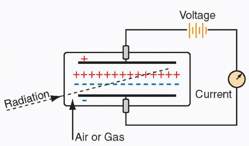
A rudimentary model includes a gas-filled chamber and an electric circuit. As radiation passes through the gas, molecules in the gas are ionized, forming ion pairs. When high voltage is applied between two areas of the chamber, the positive ions are attracted to the negative side of the detector (
cathode), and the free electrons travel to the positive side (
anode). Often, the cathode is the wall or coating of the chamber and the anode is the wire in the chamber. Electrons move through the circuit to the cathode and reunite with the cations, generating a current. This small current is measured and displayed as a signal. With more radiation, there is greater current. Common gas-filled detectors include ionization chambers, proportional chambers, and GM counters (
Figure 9.1).
The type of gas within the chamber determines the needed energy for ionization. Typically, 20 to 45 electron volts (eV) is required to form an ion pair. The number of electrons measured depends on several factors, such as the radiation being measured, energy of the radiation, geometric configuration of the detector, and gas composition and volume within the chamber, as well as the pressure and temperature of the gas. The most important determinant, however, is the applied voltage between the anode and cathode.
Voltage response curve
The voltage response curve for a gas-filled detector illustrates the relationship between the applied voltage and the amount of
electrical charge collected, or signal, after a single photon or particle interaction. The shape of the curve is best understood by examining each of its six regions in detail.
Recombination region: If the applied voltage is low, then the electrons move so slowly that they can recombine with ionized gas molecules. With increasing voltage, more ions are gathered and fewer reunite, resulting in increasing current. No usable detectors operate in this range.
Ionization (saturation) region: Most ion pairs are collected and further voltage increase does not result in increased current. There is a wide range over which the response is relatively flat, and the size of the signal is proportional to the rate at which photons or particles are interacting with the detector. Dose calibrator and ionization survey meter operate in this range.
Proportional region: At higher voltages, the electrons are accelerated to such a degree that they produce further ionization, known as gas multiplication, resulting in amplified current. As applied voltage is increased, amplification increases. Proportional detectors operate in this region.
Limited proportionality region: In this region, the positive ions formed from radiation interaction with the gas molecules slowly drift to the cathode and the electrons are attracted to the cloud of positive ions as well as to the anode. Gas amplification decreases and there is no longer a linear relationship with increasing voltage, limiting radiation detection.
GM region: Gas multiplication extends the length of the anode and further current amplification cannot occur. The amount of electrical charge collected from each radiation interaction is the same, independent of the amount of energy collected at the detector.
Continuous discharge region: At voltages greater than the GM region, gas-filled detectors continuously discharge and cannot be utilized (
Figure 9.2).
Current mode and pulse mode operation
Electrons formed in the gas-filled chamber travel to the anode. The number of electrons at the anode correlates to the amount of radioactivity or strength of the radiation field. Most detectors generate an electrical signal after each photon or particle interaction. Signal modification by electronic circuitry includes amplification, processing, or data storage. Pulse mode and current mode are two main ways a signal is processed.
In pulse mode, a signal from each photon or particle interaction is processed individually. Each interaction must be separated by a sufficient time interval to render a separate signal electrical pulse, termed the dead time of a detector system. If an interaction occurs during this dead time, its signal is lost. At higher interaction rates, the percentage of interactions lost from dead-time effects is greater. Dead time varies depending on the detector system. Pulse mode detectors require a lower rate of radiation interactions than do current mode detectors. Geiger counter, semiconductor detectors, and scintillation detectors operate in pulse mode.
Detectors operated in pulse mode can be further divided into paralyzable and nonparalyzable systems. In a paralyzable system, an interaction occurring in the dead time will extend the dead time. At very high interaction rates, the dead time will lengthen infinitely, and a paralyzable system will not detect subsequent interactions after the first interaction, falsely lowering the count rate. In a nonparalyzable system, an interaction occurring during the dead time is not recorded but does not extend the dead time.
In practice, dead time ranges from about 2 µs in a scintillation detector, to about 5 µs in a gamma camera, to about 50 to 100 µs in a Geiger counter. One should be aware that the true count may vary from the detector records, particularly at high count rates (
Figure 9.3).
In current mode, the signals from separate interactions are averaged together, forming a net current signal. Detectors operating in current mode utilize a power supply that constantly keeps the anode and cathode charged to full capacity. As electrons produced from radiation-induced ionization neutralize some of the charge at the capacitor, electrons flow from the power supply to restore charge. This electron flow is the measured current, which is based on time-averaged numbered ionizations per second. These detectors, like dose calibrators and ionization survey meters, encounter high interaction rates and operate in the ionization range of the voltage response curve. They often operate in current mode to avoid dead-time losses. At low levels of radiation, current mode detectors are susceptible to statistical variations.
Dose calibrators
Dose calibrators assay activities of patient radiopharmaceutical doses. Federal and state regulations require that doses of X- and gamma ray
–emitting radiopharmaceuticals be measured before patient administration. It is calibrated in units of Curies (Ci) and/or becquerels (Bq) (
Figure 9.4).
The majority of dose calibrators are sealed-well-type ionization chambers containing pressurized argon gas (Z = 18) to increase sensitivity. These detectors operate in the ionization range of the voltage response curve, so all primary electrons from ionization in the gas chamber travel to the anode without gas amplification. Current mode operation allows for steady state to be achieved within a couple of seconds, and the voltage supply is approximately 150 V.
The surrounding cylindrical lead shielding reduces exposure to the operator and minimizes contamination from nearby external radioactive sources. There is gamma-ray backscatter from the lead into the ionization chamber, causing increased ionization events and, therefore, increased current. Because the calibrator is calibrated with shielding present, the detector’s readings are valid only with shield in place. The calibrator does not directly measure activity and cannot discriminate between different radioisotopes. Instead, it measures the intensity of the emitted radiation by the radiopharmaceutical dose. The manufacturer determines calibration factors relating the magnitude of the signal from the detector to the activity for specific radioisotopes. This calibration curve is developed using a series of long-lived radioisotope standards from the National Institute of Standards and Testing (NIST). From this curve, conversion factors for the short-lived radioisotopes used in clinical practice are determined and programmed into the instrument. The technologist selects the radioisotope being measured, the appropriate conversion factor is applied, and the instrument displays the measured activity. Importantly, if the wrong isotope is selected, the measurement will be inaccurate. Dose calibrators are accurate down to about 20 µCi. If measurement is desired below this limit, a sodium iodide scintillation detector should be utilized.
Dose calibrators have an electronic means of zeroing the background when the well is empty. This process should be performed at least once per day and ideally throughout the day. The chamber contains a removable liner to protect it from potential contamination. Liners and ladles can be cleaned if contamination is suspected.
Pure beta-emitting radionuclides usually cannot be measured directly in a dose calibrator because the particle cannot penetrate the liner and wall of the chamber to interact with the pressurized
gas. Nevertheless, most calibrators can estimate the dose using a programmed correction table on the basis of the Bremsstrahlung emissions of the radioisotope.
Ionization survey meters
Also called ion chambers or exposure rate meters, ionization survey meters typically measure exposure rates in radiation fields. They are battery powered (50-500 V) gas-filled detectors that function in the ionization region of the voltage response curve and are operated in current mode. Various gases can be used in the ionization chamber. However, most ionization survey meters utilize air in the chamber, and the material of the chamber walls has an effective atomic number comparable to air. In this way, the generated current is proportional to the exposure rate (exposure is the amount of electrical charge produced per mass of air). Primarily, these portable survey meters are used for radiation protection purposes and can detect exposure rates over a large range.
In very high radiation fields, there can be signal loss from the recombination of ions in the chamber before they contribute to the generated current. To minimize this loss, these detectors are modified to have a small gas volume, low gas density, or a high applied voltage. They have a thin entrance window made of a low atomic number material, like mylar or mica, that has a sliding or removable cover. If gamma-emitting radiation is to be detected, then the cover is left in place, thereby excluding particles like beta or alpha particles. If particles or low-energy gamma photons are to be measured, then the cover is removed (
Figure 9.5).
Ionization survey meters and GM survey meters/Geiger counters often have overlapping uses; however, there are notable distinctions between these types of instruments. Ionization survey meters function best with higher radiation fields and are accurate to a lower limit of 1 mR/h. They are ideally suited for monitoring patients receiving therapeutic doses of radiopharmaceuticals or radioactive implants, but are not effective for radioactive contamination surveys. Because they have a fairly constant response over a wide range of gamma energies, they are useful for measuring radiation fields containing multiple radioisotopes.
Proportional counters
In contrast to ion chambers, proportional counters operate in the proportional range of the voltage response curve and rely on gas multiplication. These chambers are designed to optimize gas multiplication using gases with low electron affinity, like xenon and argon. The primary advantage of proportional counters over ion chambers is that the electrical signal generated by a single radiation event is much greater. Because of their low efficiency for higher X-rays and gamma rays used in medical imaging, they are usually restricted to research applications measuring nonpenetrating radiations, like alpha and beta particles.
GM survey meters/Geiger counters
GM counters are gas-filled detectors designed for maximum gas multiplication effect and function in the GM region of the voltage response curve. They need minimal additional signal amplification and are primarily used as survey meters for radiation protection purposes because they can detect minimal amounts of gamma contamination.
GM counters are operated in pulse mode, and the units of measurement can be displayed as counts per minute (cpm), exposure units of mR/h, or both. Calibration for exposure units is performed using a fixed gamma-ray source. In this way, the reading will vary with source strength at energy. If the measured radiation field contains gamma photons of differing energies, the conversion to mR/h is not accurate for all of the gamma rays and displayed readings are only approximations. They also cannot discriminate between radiation events of different energies based on pulse size, because all pulses are the same size. Therefore, GM counters should not be used as precise dose-rate meters. Rather, they are better suited in a qualitative or semiquantitative manner to detect small amounts of gamma photons (
Figure 9.6).
GM survey meters can be battery operated using direct current or can be powered from a wall outlet, converting alternating current to direct current internally. Often, the gas in the ion chamber is argon or helium. These meters are usually portable and are relatively sturdy. Some have audible alarms, allowing the operator to “hear” the radiation detection. They have a logarithmic scale permitting detection over a wide range, and the detector can be pancake or tube shaped depending on its use.
As with ionization survey meters, GM counters have a thin entrance window to allow radiation particles to enter, protected by a screen or cover. The cover must be removed if particles are to be detected in addition to gamma photons. These windows are easily damaged, so the survey meter should be handled with care. Otherwise, the ion chamber gas may escape, and the instrument may become useless.
GM counters have long dead times and are infrequently used when accurate measurements are needed at count rates greater than a few hundred counts per second. Portable GM survey meters can become paralyzed in very high radiation fields, rendering a zero reading. Instead, ionization chamber survey meters should be employed in high gamma-ray or high X-ray fields.
Quality control
Radiation detection systems are subject to a variety of malfunctions, resulting in their performance deterioration either acutely or gradually. For this reason, a nuclear medicine department must rigorously adhere to a QC program. A QC program also includes documentation of these practices and organized record keeping in chronologic order.
Often, QC tests are not performed with short-lived radioisotopes used clinically. Instead, long-lived surrogate radioisotope standards are employed. These standards must be traceable to the NIST to ensure the accuracy of its calibrated activity. Frequently, standards can be used for months to years because they are long-lived. Reference standards must be tested annually for radioactivity leakage (wipe tested), and a current list of these sources must be maintained. These long-lived sources remain radioactive even after they are no longer useful as a standard. They must be returned to their manufacturer or be disposed of as radioactive waste through an authorized third party.
Common Long-Lived Radioisotopes Used in Instrument QC
Refer to
Table 9.1 for a list of commonly used radioisotopes.
QC for Ionization Survey Meters and GM Survey Meters
Generally, QC tests for survey meters include daily battery check with a readout displaying whether the supply voltage is within acceptable range. Background exposure or counting rate should be checked daily in a nonradioactive area to ensure the instrument is not contaminated. These meters should be assessed daily for constancy of response by measuring the exposure rate or counting rate of a reference source. Readings from day to day should be similar, to within about 10%. Accuracy testing of the survey meter is performed at installation, yearly and after service/repair by a commercial calibration facility or the institutional radiation safety office.
QC for Dose Calibrators
Dose calibrator constancy must be tested daily using an NIST-traceable reference source, like 57Co, 133Ba, 68Ge, or 137Cs. Daily activity readings should fall within ±10% agreement.
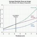
Quarterly assessment of activity linearity can be performed using the decay method or the shield method. Decay method utilizes an independently calibrated 99mTc source that is assayed at 12-hour time points over 3 days. The measured activities are plotted on a semilogarithmic graph with time in the x-axis. For each time point, the difference between the measured activity and the best-fit straight line at that point should be less than 10%. The shield method uses a set of commercially available lead sleeves of varying thickness that simulate decay via attenuation. Before use, these sleeves must be calibrated by comparing with the decay method.
Accuracy is checked annually using a reference standard traceable to the NIST. It requires three separate measurements of the source, which are averaged and compared to the known activity. This procedure is repeated with two or three sources of differing gamma energies. The reading must be within ±5% of the reference activity to be accurate.
Geometry testing occurs at installation and after repair or adjustment and is performed by the manufacturer. A small volume of the radiopharmaceutical, such as
99mTc pertechnetate, is placed
in a vial or syringe and its activity is measured after each dilution. If the volume affects the measurements by more than ±10%, a correction factor must be established.
Molybdenum-99 Concentration Testing
With 99Mo/99mTc generator elution, there is a potential for 99Mo contamination in the eluate. If the eluate is administered to a patient, the patient will receive increased radiation dose (99Mo emits high-energy beta particles and has a half-life of 66 hours). Furthermore, the image quality can be compromised by the high-energy 99Mo gamma photons. The limit at time of administration is 0.15 µCi of 99Mo per 1 mCi of 99mTc. The first elution of the generator must be assayed for 99Mo concentration.
The concentration of 99Mo is usually measured with a dose calibrator using a lead container provided by the manufacturer. The walls of the container will prevent 140 keV gamma photons from 99mTc but are insufficient to block the higher gamma photons from 99Mo (740 and 778 keV).
82Sr and 85Sr Concentration Testing
PET myocardial perfusion imaging can be performed using 82Rb chloride, which is acquired from an 82Sr/82Rb generator. With generator elution, 82Sr or 85Sr contamination can occur in the eluate. The limit at the time of administration is 0.02 kBq of 82Sr or 0.2 kBq of 85Sr per 1 MBq 82Rb. A dose calibrator is used to measure the contaminants, following the manufacturer instructions in the package insert.
Recommended QC Tests for Gas-Filled Detectors
Refer to
Table 9.2 for the recommended QC tests for gas-filled detectors
Scintillation detectors
Scintillation detectors are an essential category of radiation detectors used in nuclear medicine. They have important advantages over gas-filled detectors. Most are solid materials, like crystals, allowing for many more interactions with gamma photons compared to gas-filled detectors. They also provide the means to measure the energy of the radiation interaction, distinguishing energies from different radioisotopes, which is not possible with gas-filled detectors. Scintillation detectors are used in both imaging and nonimaging applications in nuclear medicine, including thyroid probes, well counters, gamma cameras, and PET cameras.
Basics
A scintillator is any material that emits a visible or ultraviolet (UV) photon when an excited electron in the material returns to its ground state. Most scintillation detectors use PMTs to convert visible or UV light to an electrical signal, which is then amplified.
Ionizing radiation interacts with a scintillator to excite electrons to a higher energy level. As these electrons return to their lower energy state, visible or UV light is emitted. There can be more than one manner of light emission, each having its own decay constant. Luminescence is defined as the emission of light after excitation. Fluorescence is the prompt emission of light after excitation, and phosphorescence (afterglow) is the delayed emission of light.
Current mode operation of the scintillation detector does not allow for the separation of the signal from fluorescence from the phosphorescence caused by prior radiation interactions. However, with pulse mode operation, the effect of phosphorescence on the signal is minimized. Circuitry is able to distinguish the prompt rise and fall of the fluorescent emission signal from the gradual decline of the phosphorescent emission signal from previous interactions.
Desired characteristics of scintillator materials include the following:
High conversion efficiency, or the fraction of deposited energy converted to visible or UV radiation
Short decay times of excited states, resulting in prompt fluorescent emission
Transparency to its own emissions, minimizing radiation reabsorption
Frequency spectrum of the emitted visible or UV radiation comparable to the spectral sensitivity of the light receptor (PMT)
Large mass attenuation coefficient (µ), high atomic number, and high density, for good X-ray and gamma-ray detection efficiency
Durability, moisture resistance, and inexpensiveness
For all scintillators, the amount of light or UV emission after a radiation interaction increases with the amount of energy deposited by the interaction. For this reason, scintillators can be operated in pulse mode as spectrometers. The energy resolution, or the capability to discriminate between photons or particles of differing energies, is mostly dependent on the conversion efficiency; the higher the conversion efficiency, the greater the energy resolution.
Organic scintillators
A variety of materials can be used as scintillators. In organic scintillators, the scintillation is an inherent property of the molecular structure. However, organic scintillators are not utilized in medical imaging, because their low atomic numbers and densities make them inefficient for X-ray and gamma-ray detection.
Inorganic scintillators/crystals
In contrast to organic scintillators, inorganic crystals are often used in medical imaging and nonimaging applications. Their scintillation is a property of their crystalline structure, not the individual elements. These materials have high atomic numbers and densities, superior for X-ray and gamma-ray detection. These crystals are grown with impurity elements to cause disturbances in the crystal matrix. These “activation centers” allow for electron excitation, affect the frequency or color of the light emission, modify promptness of fluorescence, and minimize reabsorption in the crystal.
Most nuclear medicine applications use sodium iodide activated with thallium, NaI(Tl). The crystal is coupled with PMTs and operated in pulse mode in scintillation cameras, thyroid probes, and gamma well counters (
Figure 9.7).
NaI(Tl) crystal has a high density (ρ = 3.67 g/cm3) and high atomic number (iodine, Z = 53), allowing for good photoelectric absorption. It has a high efficiency for detecting X-rays and gamma rays in the 70 to 250 keV range, which includes most medical radiopharmaceuticals. It has high conversion efficiency with about 13% of the energy deposited at the crystal converted to light, rendering superior energy resolution. Its fast light emission allows for pulse mode operation at high interaction rates (>100 000/second). It is transparent to its own scintillation emissions with minimal reabsorption, even in large crystals. Crystals can be grown as large plates, useful in imaging equipment.
Its main disadvantages include its susceptibility to mechanical and thermal stresses and its tendency to absorb moisture. At higher gamma energies, the primary interaction is Compton scatter and detection efficiency decreases.
For the detection of the 511 keV emissions from positron emitters, denser scintillators are required. Early PET detectors included bismuth germinate (Bi4Ge3O12, or “BGO”) crystals. Lutetium oxyorthosilicate (Lu2SiO4O, or “LSO”), lutetium yttrium oxyorthosilicate (LuxY2 − xSiO4O, or “LYSO”), and gadolinium oxyorthosilicate (Gd2SiO4O, or “GSO”), all activated with cerium, are used in newer PET/CT scanners. These materials have high densities and high atomic numbers, but they have even greater conversion efficiencies and faster light emission compared to BGO.
Photomultiplier tubes
PMTs serve two purposes—conversion of light or UV emission into electrical signal and signal amplification. Thyroid probe and well counters each have one PMT, whereas gamma cameras have many PMTs, permitting both energy and position determination (
Figure 9.8).
As depicted in
Figure 9.8, a PMT is an evacuated glass tube containing a photocathode, a series of 10 to 12 electrodes (dynodes), and an anode. The photocathode is the front surface of the entrance window of the PMT coated with a photoemissive material that ejects electrons (photoelectrons) when struck by light photons, usually metal alloys with extra electrons, like bialkali antimonide compounds (K
2CsSb and Na
2CsSb). Conversion efficiency is about 1 to 3 photoelectrons per 10 light photons. The focusing grid is an electrical field that directs the emitted photoelectrons to the first dynode. It is critical that the vacuum of the PMT is maintained so that no electrons are lost via gas molecule interactions. PMTs are also shielded from magnetic fields so that electron trajectory is not altered.
The first dynode is a curved metal plate a short distance from the photocathode, and it is coated with a material having high secondary emission properties. The dynode is maintained at a positive voltage (+100 to 200 V) relative to the photocathode, attracting the photoelectrons to it. The accelerated photoelectron strikes the dynode, ejecting about five secondary electrons from it. Each dynode is maintained at successively higher voltages (+100 V increments), resulting in greater electron multiplication.
The total amplification of the PMT is equal to the product of the individual multiplication at each dynode. For example, if a PMT has 10 dynodes and the multiplication at each step is 5, then the total amplification is
510, or approximately 10 000 000.
In this manner, a large electrical current is produced despite a relatively weak light emission. Amplification can be modified by changing the applied voltage to the PMT. PMTs require a high voltage supply, which must remain stable given the sensitivity of the electron multiplication factor to dynode voltage changes.
Between the back of the crystal and the PMT, there is usually a light pipe consisting of quartz or lucite, reflecting back any wide-angled scintillation photons toward the PMT photocathode. Optical coupling grease minimizes scintillation photon loss by preventing reflections at component interfaces. If the grease degrades, fewer scintillation photons will reach the PMT.
Preamplifier and amplifier
The preamplifier is directly attached to the PMT to lessen signal distortion, and augments the output signal. The amplifier further increases the signal as well as shapes the pulse for the pulse height analyzer (PHA).
Pulse height analyzer
The PHA determines the height of the pulse generated by the PMT, which is proportional to the energy absorbed in the crystal from gamma photon interaction. However, with each step in this conversion process, gamma photon to light photon to electrons, there is inefficiency and energy loss. For this reason, the pulse height, or measured output, is not exactly proportional to the incidental gamma ray, and instead is a distribution of pulse heights around the true gamma ray energy. Such broadening of energy peaks in the measured spectra poses challenges for discrimination between gamma photons of similar energies (
Figure 9.9).
There are two types of PHAs: the single-channel analyzer (SCA) and the multichannel analyzer (MCA).
SCA Systems
Signal pulses from the PMT are routed to the preamplifier and then the amplifier, which augment the signal. The pulses then travel to the SCA. The operator can set a lower voltage level (LL) and an upper voltage level (UL). If a signal pulse is above the UL or is below the LL, the SCA does not accept the pulse. If the pulse falls within the set voltage levels, the SCA produces a single logic pulse of a fixed amplitude and duration. These output pulses can drive counters, rate meters, and other circuits. SCA extracts the gamma-ray energy information from the voltage signal and, based on that energy, accepts or rejects that pulse. The SCA output is a series of binary logic pulses (yes/no or 1/0) that can be counted but contain no additional information about the gamma photons they represent.
MCA Systems
The major disadvantage of an SCA system is the rejection of gamma interactions that do not fall between the LL and UL voltage levels. In contrast, the MCA depicts all energy interactions on an energy graph, or
pulse height spectrum. The number of detected events, or counts, is graphed against the amplitude of those events, or gamma energy (
Figure 9.10).
The MCA system has an analog-to-digital converter (ADC), which measures and sorts the incoming pulses by their amplitudes. Typically, the pulse amplitude range is 0 to 10 V, sorted by the ADC into separate bins, or channels. For example, a 1000-channel analyzer would divide the 0 to 10 V amplitude range into a 1000 channels, each 0.01 V wide (10/1000). Channel 1 would correspond to 0 to 0.01 V, channel 2 would correspond to 0.01 to 0.02 V, channel 3 would correspond to 0.02 to 0.03 V, etc. The ADC would assign a signal pulse to a specific channel number, converting an analog pulse into a digital value. The MCA memory counts and stores the number of pulses within each channel. The pulse height spectrum can then be displayed as counts per channel versus the channel number, or energy.
Energy spectra
The generated spectrum from the MCA has several identifiable peaks. The right-most peak in the spectrum is the
photopeak. It corresponds to the gamma rays that have undergone photoelectric conversion in the scintillation crystal. Peaks to the left of the photopeak represent photons that did not deposit their full energy on the crystal, many of which have undergone Compton scatter effects (
Figure 9.11).
The photopeak (A) is the total absorption of the 140 keV photons by the crystal. The iodine escape peak (B) is due to the 140 keV photons interacting with the iodine in the crystal and causing iodine K-shell X-rays (28-33 keV) to escape. Photopeak (C) is due to the absorption of K-shell X-rays from the lead shielding. Lower energies represent Compton scattering with the scattered photons escaping the crystal.
An energy window can be set, centered on the photopeak, to exclude the other energy peaks. The window is specified as a percentage of the photopeak energy. A narrow window (2%-5%) would be used for calibration and a wider window (15%-20%) for imaging and other clinical applications.
Energy resolution
Energy resolution describes the detector’s ability to discriminate photons of closely spaced energies. The width of the photopeak is a measure of the energy resolution. Because of statistical fluctuations in the detection process, the peak has a spread around
a mean value. The spread is the full width at half maximum (FWHM) of the photopeak (
Figure 9.12).


 Get Clinical Tree app for offline access