X-ray Imaging: Radiography and Fluoroscopy
Zhihua Qi, PhD
LEARNING OBJECTIVES
1. Describe the functions of the main components of an X-ray tube, including the cathode, the anode, the collimator, and the filters.
2. Describe the roles of an X-ray generator and its desired characteristics for medical imaging.
3. Explain the working principles of the image receptors used by three types of X-ray imaging technologies: screen-film radiography, computed radiography, and digital radiography.
4. State the differences between indirect conversion and direct conversion in digital radiography.
5. Describe both the effects of scatter on image quality and the main techniques used for scatter reduction in radiography.
6. Explain how technical parameters of a radiographic acquisition affect image quality.
7. Describe the differences between image intensifier-based and flat panel detector-based fluoroscopic systems.
8. Explain the benefits of the pulsed mode in fluoroscopy compared to the continuous mode.
RADIOGRAPHY
X-ray radiography is the most commonly performed X-ray imaging examination. It produces one or more planar views of the anatomy of interest for quick diagnosis of many common conditions.
Radiographic technologies
Radiographic technologies are featured by the image receptor technologies for image acquisition. Screen-film radiography was the mainstream technology before the digital trend in radiography. Computed radiography and digital radiography are both radiographic technologies with digital capabilities.
Screen-film radiography
Before the digital era of radiology, screen-film cassettes were the majorly used X-ray image receptor. A screen-film cassette encapsulates intensifying screens inside a light-tight cassette and is loaded with a sheet of film during the exposure for imaging.
Film
The film inside a screen-film cassette converts incident light photons into varying levels of darkness as a function of light flux. It is composed of a thin plastic base coated on one or both sides with a light-sensitive emulsion layer, which consists of silver halide (AgBr and AgI) crystals held inside water-soluble gelatin (Figure 3.1). Each silver halide crystal has on its surface specks of Ag+ ions because of artificially introduced defects to the crystal lattice. When a grain of silver halide crystal is exposed to visible light, a small number of Ag+ ions on the crystal surface gain electrons and get reduced to metallic Ag atoms, and, as a result, the crystal grain forms a stable latent center locally. The opacities introduced by these Ag atoms are still too weak to form a visible image; hence a developing process is needed to amplify the signal by converting all Ag+ ions at each latent center to Ag atoms (Figure 3.2). After film development, the film then has its residual silver halide crystals in unexposed areas dissolved by a bath of an aqueous oxidizing solution called fixer before it is rinsed and dried for image presentation.
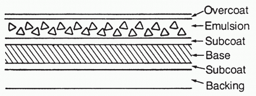 FIG. 3.1 • Cross-section view of X-ray film. Reprinted with permission from Christman R. Foot and Ankle Radiology. 2nd ed. Philadelphia, PA: Wolters Kluwer; 2015. |
A developed film is viewed in front of a light box. The local darkness of the film is caused by the presence of Ag atoms after they are converted from ions and reflects local X-ray exposure made during image acquisition; the higher the exposure, the darker the area. Film images are therefore considered as negative images.
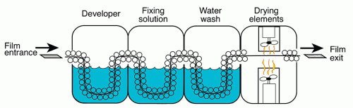 FIG. 3.2 • Processing of radiographic films. Reprinted with permission from Wilkins EM. Clinical Practice of the Dental Hygienist. 12th ed. Philadelphia, PA: Wolters Kluwer; 2017. |
Screen
An intensifying screen is primarily made of scintillator materials, which convert incident X-ray exposure into visible light photons, whose wavelengths fall into the sensitive range of the film.
In selecting the appropriate thickness of an intensifying screen, there is a trade-off between the spatial resolution of the image and the efficiency of X-ray absorption. When the screen thickness increases, more incident X-ray photons are absorbed by the screen, but the visible light photons have a broader spread before reaching the film, leading to a blurred image. When the screen thickness decreases, less blurring of the image is expected at the expense of a more grainy/noisy image.
Speed is a common term used to describe the efficiency of X-ray absorption by a radiographic image receptor. The higher the speed, the less radiation it takes for a certain level of signal output (the optical density of the film is the signal output for screen-film radiography).
Screen-Film Configuration
Radiographic applications often use screen-film cassettes with a double-emulsion and double-screen configuration, in which the film has two emulsion layers and is placed in between two screens for the maximum efficiency of X-ray absorption (Figure 3.3). The configuration becomes different for applications where high spatial resolution is desired, like mammography; only a single screen is used and placed behind the film along the X-ray path so that X-ray photons hit the film first. In this configuration, there are more X-ray photons absorbed by the screen at places near the film because of X-ray attenuation, and the resulting light spread is limited; if X-ray photons hit the screen first, there would be more photons absorbed by the screen at places far from the film and there would be more light spread.
Computed radiography
In computed radiography, the screen-film cassette is replaced by a photostimulable phosphor (PSP) plate. A PSP imaging plate is typically made of a mixture of BaFBr and BaFI, activated with a small quantity of Eu (europium). When X-ray energy is absorbed by the phosphor, electrons associated with the europium atoms are excited and become mobile, and then a fraction of them will get trapped locally in a higher energy state. The number of trapped excited electrons per unit area of the imaging plate is proportional to the intensity of X-rays incident at each location of the detector during the X-ray exposure. When a red laser beam scans the exposed imaging plate, the trapped electrons absorb energy from the light photons and become mobile again (Figure 3.4); when these electrons return to their ground state, they release energy in the form of blue light photons. The photons will be captured by a light guide and measured for image formation.
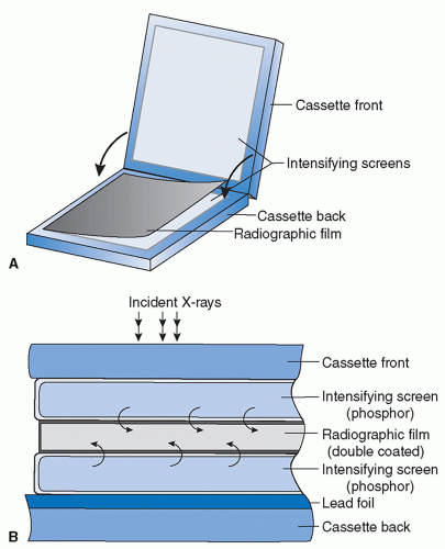 FIG. 3.3 • A screen-film cassette whose configuration is featured by a double-emulsion sheet in between two phosphor screens (A). Compared to the use of single-emulsion film and/or single screen, this configuration has high sensitivity to incoming X-rays at the expense of compromised spatial resolution (cross-sectional view shown in B). Reprinted with permission from Smith WL. Radiology 101. 4th ed. Philadelphia, PA: Wolters Kluwer Health/Lippincott Williams & Wilkins; 2014. |
The light released by the imaging plate has higher energy and shorter wavelength than the stimulating laser light. In fact, the stimulating laser light used by readers of PSP imaging plates is red in color (˜600-700 nm wavelength), and the emitted photons coming out of the screen are blue (˜400-450 nm wavelength). The separation in the wavelength profiles between the two groups of light photons allows efficient detection and accurate quantification of the light photons and the incident X-ray exposures.
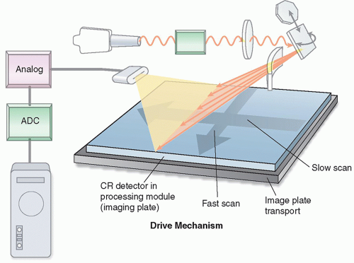 FIG. 3.4 • Image readout of a photostimulable phosphor plate inside a reader. Reprinted with permission from Orth D. Essentials of Radiologic Science. 2nd ed. Philadelphia, PA: Wolters Kluwer; 2017. |
Digital radiography
Flat panel detectors (FPDs), as a digital X-ray imaging technology, have the following advantages: (1) the images are instantaneously available after the exposure and (2) its area is sufficiently large to support most clinical applications without the need of optical coupling. X-ray detection by FPD is a two-step process: first, detected X-ray photons are converted into charges; then these charges are collected and read out by dedicated electronics. Although there are different designs for converting X-ray photons to charges, the handling of the charges in the second step is nearly the same for all FPDs.
An FPD is made on a flat piece of amorphous semiconductor material. It is divided into a large array of squared pixels arranged in a row by column matrix. Regardless of the design in converting X-ray photons to charges, each pixel has at least the following components: an electrode for charge collection, a storage capacitor to hold the charge, and a thin-film transistor to coordinate the readout of the charge. The entire array of pixels forms an active matrix structure, through which charges collected by each individual pixel can be read out in a coordinated fashion.
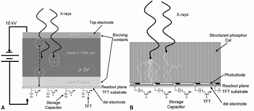 FIG. 3.5 • A and B: Cross-sectional views of both indirect conversion and direct conversion detectors. Reprinted with permission from Kandarpa K, Machan L, Durham J. Handbook of Interventional Radiologic Procedures. 5th ed. Philadelphia, PA: Wolters Kluwer; 2016. |
The conversion from X-ray photons to electrical charges may be either indirect or direct (Figure 3.5).
Indirect Conversion Detector
Indirect conversion FPD uses a scintillator mounted on the front surface of the detector. The scintillator functions in the same way as that in a screen-film cassette by converting incident X-ray photons to light photons. The light photons then reach the pixels, and each individual pixel, with its photodiode, converts the light photons to electrical charges before their readout. Light photons produced inside the scintillator layer diffuse in all directions while exiting the scintillator, eventually causing a blurring of the signal and a loss of resolution in the formed image. To reduce such resolution loss, most indirect conversion detectors use cesium iodide (CsI) as the scintillator material. CsI has a columnar crystal structure that acts like light pipes to reduce lateral spread of light.
Direct Conversion Detector
Direct conversion FPDs eliminate the production of light photons and directly convert X-ray photons into charges. Amorphous selenium is the semiconductor material most commonly used for fabricating the layer at the entrance of the detector. The semiconductor layer produces electron-hole pairs in proportion to the incident X-ray intensity, and the ion pairs are instantly collected by the applied voltage across the layer and transferred to individual pixels for subsequent readout. This design minimizes the spread of signals and results in high spatial resolution in the acquired images.
Scatter management
X-ray imaging follows a straight-line assumption, that is, each X-ray remains on a straight-line trajectory while traveling through tissues, regardless of the interactions it may have with the tissues. Scattered X-rays often deviate from their original trajectory after interactions with tissues and cause displacement of information, overlapped with information from the nonscattered or primary X-rays on the image receptor. Effects of scattered radiation include reduction in image contrast and loss of spatial resolution.
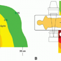
The amount of scattered radiation in an image is characterized by the scatter to primary ratio (SPR), defined as the amount of energy from scattered X-rays, divided by that from primary X-rays. The SPR is a function of both tissue thickness and the field of view used for acquisition (Figure 3.6). In acquiring an abdominal X-ray image for a normal-sized adult patient (˜25 cm tissue thickness), the SPR is about 4, meaning that, if uncorrected, 80% of the photons used for forming the image are scattered radiation.
Antiscatter grid
Antiscatter grids are widely used in X-ray imaging for scatter reduction (Figure 3.7). It is placed in between the patient and the image receptor and made of a large number of highly absorbing lead septa with interspace supporting materials in between. All the septa are aligned with the focal spot of the X-ray tube so that most primary photons reach the image receptor with minimal attenuation from interspace materials, whereas the scattered photons, deviating from their original paths, largely get absorbed by the septa. Lead is typically used for making the grid septa, whereas carbon fiber, giving little attenuation and providing necessary structural support, is a common interspace material.
Most antiscatter grids used in routine radiographic examinations are linear or one-dimensional, meaning the septa and interspace materials alternate along one dimension only. Two-dimensional grids have found uses in mammographic applications.
It is worth mentioning that antiscatter grids absorb both scattered and primary X-ray photons. Therefore, the reduction of scatter by the use of grids comes at a penalty of increased radiation to the tissues, because an increase in radiation is necessary to compensate for the loss of signal detected by the image receptor. This increase is described by the Bucky factor. Typical Bucky factors for grids used in abdominal X-ray imaging are between 3 and 8. The Bucky factor has more relevance in screen-film radiography than digital radiography. This is because screen-film cassettes have a fairly narrow dynamic range and the loss of signals by the use of grids would result in an underexposed film, whereas digital detectors have a wider dynamic range and allow for postprocessing that may compensate for at least part of the loss.
Related posts:

Stay updated, free articles. Join our Telegram channel

Full access? Get Clinical Tree


