-error is similar in both implementations and decreases linearly with the spatial step size. Finally, we test the performance of the implementations with networks of varying complexity, where the hybrid implementation is, on average, 5.8 times faster.
1 Introduction
The cardiac Purkinje fibre network is an important contributor to the coordinated contraction of the heart as it can provide a fast conduction system reaching out to large areas of the sub-endocardium. The Purkinje fibres form an extensively branching and rejoining network, which is important for the reliability and fault-tolerance of the propagation of the action potential [1, 2]. The ability to simulate propagation in physiological Purkinje networks is essential for studies of the healthy heart to obtain realistic activation patterns [3, 4]. It is equally important in the simulation of pathological hearts, where disturbances in the conduction system can alter the activation pattern greatly, e.g. bundle branch blocks and long duration ventricular tachycardia [5].
Typically the simulation of the action potential propagation in a Purkinje network is based on the bidomain equations [6], or on the cable equation with a reaction term [7]. The approach of Vigmond et al. [7] treats the Purkinje conduction system as a branching tree of conducting segments without loops. Our approach also allows current loops in the Purkinje network, which are observed in realistic Purkinje networks [2].
We present first briefly the approach of Vigmond et al., and then explain its implementation on the CPU and on a CPU/GPU hybrid platform. Then, we present a simple model with exact known solution and use it for verification of both solvers. Finally, we compare the performance of both implementations.
2 Methods
2.1 Mathematical Model and Solution Method
The electrophysiology of cardiac tissue can be described either by the bidomain or the monodomain model. The former assumes an extracellular and intracellular space with different anisotropic conductivity tensors; if these tensors are linearly dependent the model reduces to the monodomain model [7].
The monodomain equation is considered in one dimension, because the Purkinje network can be approximated by a network of 1-D line segments. Here we assume that the extracellular space is not affected by the Purkinje network, and ignore it in the following. The monodomain equation reads

where x is the local coordinate,  is the transmembrane potential,
  is the current that flows through the ion channels,
  are the state variables of the membrane model,
  is the surface-to-volume ratio of the cell membrane, where
  is the intracellular conductivity, and
  is the membrane capacitance.

(1)
 is the transmembrane potential,
  is the current that flows through the ion channels,
  are the state variables of the membrane model,
  is the surface-to-volume ratio of the cell membrane, where
  is the intracellular conductivity, and
  is the membrane capacitance.
To derive a coupling condition between two or more line segments, needed to complete (1), we follow the idea of Vigmond et al. [7]. The equations on each line segment are coupled together by a boundary condition resulting from the enforcement of continuity of the potential and the conservation of charges (Kirchhoff’s law). To satisfy the boundary conditions, the transmembrane potential,  , and the current, I, are needed. Since
  , the spatial derivatives of the potential need to be computed. The system is discretized using a cubic Hermite finite element method (FEM), which allows the current I to be recovered as a continuous quantity.
 , and the current, I, are needed. Since
  , the spatial derivatives of the potential need to be computed. The system is discretized using a cubic Hermite finite element method (FEM), which allows the current I to be recovered as a continuous quantity.
In view of the numerical discretization with the Finite Element Method, each node of the mesh is assumed to be located in the gap junction between two cells, where the unknowns are the intracellular potential  and the current
  through the gap junction. Two ghost nodes are created on both sides of the gap junction, where the transmembrane potential
  , and ionic channel current
  are defined. The advantage of the ghost nodes is that with the gap junction modelled as a resistor R, the current
  can be obtained from Ohm’s law

where  is the extracellular potential, taken constant in this work.
 and the current
  through the gap junction. Two ghost nodes are created on both sides of the gap junction, where the transmembrane potential
  , and ionic channel current
  are defined. The advantage of the ghost nodes is that with the gap junction modelled as a resistor R, the current
  can be obtained from Ohm’s law
(2)
 is the extracellular potential, taken constant in this work.
To correct for the introduced gap junction resistance, we use the equivalent conductivity  , where l is the length of the Purkinje cell and
  the radius. This means, that
  is the conductivity in the cell only, while
  is the conductivity of the cell and the gap junction. In this notation (1) becomes

where  is the intracellular potential in the ghost nodes. Furthermore, we apply an operator splitting technique to (3):

where  is part of the differential operator that represents the nonlinear term of (3), whereas
  represent the diffusion term of (3). A fractional-step method with a discretization of the temporal derivatives by a first-order approximation is introduced, where the superscript n refers to the numerical solution computed at time
  :
:


 , where l is the length of the Purkinje cell and
  the radius. This means, that
  is the conductivity in the cell only, while
  is the conductivity of the cell and the gap junction. In this notation (1) becomes
(3)
 is the intracellular potential in the ghost nodes. Furthermore, we apply an operator splitting technique to (3):
(4)
 is part of the differential operator that represents the nonlinear term of (3), whereas
  represent the diffusion term of (3). A fractional-step method with a discretization of the temporal derivatives by a first-order approximation is introduced, where the superscript n refers to the numerical solution computed at time
  :
:
(5)

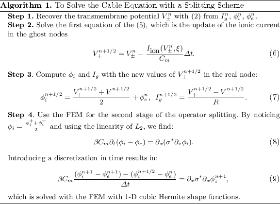
Now the cable equation can be solved in four steps (Algorithm 1). To handle branching and joining of segments in the network, the node where the three segments join is triplicated. The triplicated point is used to enforce the boundary conditions, and thus couple together the solutions obtained for the different line segments. In the case that segment 1 bifurcates into segments 2 and 3, we enforce the continuity of the potential  and the conservation of current
  . In contrast to Vigmond et al., our implementation covers the case where segments 1 and 2 join to from segment 3, in which case the coupling condition of the currents is
  . These boundary conditions are introduced in the FEM system matrix associated to (9) and the right hand side.
 and the conservation of current
  . In contrast to Vigmond et al., our implementation covers the case where segments 1 and 2 join to from segment 3, in which case the coupling condition of the currents is
  . These boundary conditions are introduced in the FEM system matrix associated to (9) and the right hand side.
2.2 Hardware Implementation
We now outline the CPU and the CPU/GPU hybrid implementations. The solver for the cable equation used the FEM in Step 4, and was implemented using the LifeV library (http://www.lifev.org). Parallelism was achieved using OpenMPI. We parallelized only Steps 1–3 of the algorithm and solve the linear system in Step 4 serially. The reason for this is that calculating the ionic model can be done without knowing the mesh geometry and is computationally intensive. On the other hand, it is less trivial to parallelize the solving of the linear system. The resulting computational workflow is shown in Fig. 1.
Stay updated, free articles. Join our Telegram channel

Full access? Get Clinical Tree


