7 Optimizing the scan
INTRODUCTION
Ultrasound scanners have a range of examination-specific presets that optimize the system for a particular examination and it is important to start the scan with the appropriate preset selected. However, in many instances the scanner controls need adjusting, or optimizing, to demonstrate pathology. In addition, a number of imaging and Doppler artifacts may be confused or misinterpreted as significant disease, leading to serious diagnostic errors. The aim of this chapter is to introduce the sonographer to the practical aspects of scanning, covering the basic use of scanner controls and reiterating some of the principles discussed in the preceding chapters. Imaging artifacts will also be discussed to assist the sonographer in the interpretation of images. It is likewise essential that the sonographer has a good understanding of the principles relating to ultrasound safety in order to minimize any exposure risks to the patient.
B-MODE CONTROLS
Always set the focal zones at the depth of interest on the scan image. B-mode frame rates of modern scanners are generally high even when multiple focus zones have been selected. If the region of interest in the B-mode image is very small, or very deep, consider using the write zoom control to magnify the area. This will improve the frame rate and allow closer inspection of the anatomy. Many vascular sonographers prefer B-mode images with a reasonable degree of contrast using a lower dynamic range. Duplex systems have examination-specific presets that are optimized to produce the best images of vascular structures. It is also worthwhile experimenting with different pre- and postprocessing controls in order to understand the function of these controls. Try this when imaging a carotid plaque and note the difference in the appearance of the image. Optimize the total gain and depth gain compensation sliders so that the returning echoes are of relatively uniform intensity throughout the image. In general, the gain should be set so that the lumen of any large nondiseased vessel appears clear or black but any further increase in gain would introduce noise or speckle. Harmonic imaging can be especially useful in the abdomen and may produce clearer and less noisy images. The use of compound imaging, may also improve the overall image.
IMAGING ARTIFACTS
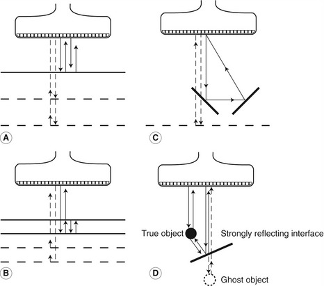
• Multiple reflections can lead to reverberation artifacts, seen as several equidistant echoes that reduce in brightness with depth. This is due to multiple reflections, along the same path, between the transducer and a strongly reflecting boundary (Fig. 7.1A) or between two parallel, strongly reflecting surfaces (Fig. 7.1B). If the multiple reflections do not return along the same path, the structure may be misplaced on the image (Fig. 7.1C).
• A mirror image of a structure can be produced in the presence of a strongly reflecting surface. Figure 7.1D shows how the true position of a structure is displayed, with a second ghost image also displayed. The ghost image has been created by an ultrasound beam that has undergone multiple reflections from the strongly reflecting surface.
• Refraction can lead to bending of the path of the ultrasound when the beam passes through an interface between two media in which the speed of sound is significantly different (see Fig. 2.7).
• Range ambiguity can occur if an echo from the previously transmitted pulse is received back from a distant boundary after the current ultrasound pulse has been transmitted. The scanner will assume that the echo is from the current pulse and place it nearer to the top of the image rather than at its true depth.
• Grating lobes are areas of lower-intensity ultrasound outside the main beam and are produced as a function of the multi-element structure of array transducers. These grating lobes can lead to strongly reflecting surfaces outside the main beam being displayed in the image.
Stay updated, free articles. Join our Telegram channel

Full access? Get Clinical Tree


