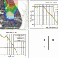
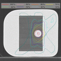
Fig. 18.1
Illustrative explanation of the image based phase recognition using NCC between adjacent projections in a limited area (yellow box), which is shifted along with the cranio-caudal axis on the next projection image (i + 1-th projection) in the search for the maximum value of NCC with the segments on previous projection images (i-th projection)
18.1.2 Phase Selecting Reconstruction
For modern helical CT scanners, the rotation cycle of the gantry is sufficiently faster than the breathing cycle, such that a single slice of a three-dimensional (3D) CT scan is regarded as belonging to a certain respiratory phase, whereas different slices represent different respiratory phases. Therefore, a 4D-CT image set can be obtained from a single CT scan by subsequently selecting the slices corresponding to a certain respiratory phase [7, 8].
For a CBCT mounted on LINAC, the rotation speed of the gantry is very slow; more than 1 min for one rotation cycle, which is considerably longer than the breathing cycle, and thus, the conventional technique developed in helical CT scans cannot be used any more. In this case, the reconstructed volumes at multiple respiratory phases can be obtained by retrospective sorting in projection space. Figure 18.2 demonstrates the method of the respiratory signal sorting with four phase bins. The projection images are classified by means of the respiratory signal. A 4D-CBCT image set is thus generated by reconstructing with each subset of projections [1, 4].
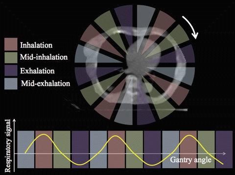

Fig. 18.2
Principle of 4D CBCT reconstruction using image-guided system mounted on LINAC. The projection images are classified into the phase bins defined with the respiratory signal. Thus, 4D CBCT set is generated by reconstructing with each subset of projections
Obviously, the image quality of 4D CBCT images is degraded due to the larger gap of the gantry-angle increment per projection than that in 3D CBCT. In order to suppress this degradation, the slower gantry speed (typically 4 min per rotation) is used in 4D CBCT imaging. The CBCT images for a moving phantom reconstructed with 3D (2 min per rotation), 4D (4 min per rotation), 4D (2 min per rotation), 4D (1 min per rotation) are shown in Fig. 18.3, where the images for the expiration phase are selected in 4D CBCT. The 4D CBCT with 1 and 2 min per rotation has a severe streak artifact, whereas the 4D CBCT with 4 min per rotation reduces this artifact.
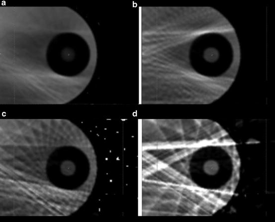

Fig. 18.3
CBCT images (Axial view) for a moving phantom (QUASAR; Modus Medical Devices Inc.); (a) 3D (2 min per rotation), (b) 4D (4 min per rotation), (c) 4D (2 min per rotation), and (d) 4D (1 min per rotation) images
The space-time information of a tumor location from the clear images of 4D CBCT would play an important role in the delivery of precise radiation therapy. However, it should be noted that the slower gantry speed in 4D-CBCT imaging could add a significant radiation dose to the patient. Therefore, it would be desirable to optimize radiation parameters to reduce the imaging dose as low as reasonably achievable. In Fig. 18.3, the mA per frame and ms per frame are 20 mA/frame and 40 ms/frame, which are clinically used in The University of Tokyo Hospital. With those parameters, the CT dose index (CTDI) volume is approximately 12 mGy for 4D CBCT imaging with 4 min per rotation, measured with a 15-cm length CTDI phantom.
18.2 Volumetric Modulated Arc Therapy for Lung SBRT
Intensity-modulated radiation therapy (IMRT) extensively includes a rotational therapy, namely intensity-modulated arc therapy (IMAT). IMAT was first proposed in 1995 as a conventional MLC with the various leaf pattern changing continuously as the gantry rotates [9]. To deliver IMRT fields in a gantry angle, several rotational arcs with different MLC patterns were considered to be required for IMAT delivery. At that time, several rotations were not realistic because it was time consuming. In addition, the fixed-dose rate delivery prohibited progress of IMAT. Nevertheless, in 2008, a variation of the gantry speed and the dose rate, and a rapid MLC control, compensated the weak points of IMAT [10]. This new delivery technique is called VMAT. VMAT achieved comparable intensity modulation level compared with IMRT [11–13]. In addition, VMAT drastically reduced the amount of the monitor unit (MU). Thus, VMAT was found to be able to deliver the desired dose distribution in a shorter time than IMRT. This feature is valuable, in particular, for SBRT [14, 15]. In fact, the delivery time is about 4 min in a conventional LINAC. Using flattening-filter-free techniques, delivery time for lung VMAT is under 2 min [16, 17].
Nowadays, VMAT plays an important role in high-precision radiation therapy treatment. On the other hand, there are some challenges in use of VMAT with regard to a moving target such the lung tumor. Clearly, if a movement occurs between delivery of any of the IMRT fields, the dose may not add up to the desired total dose as planned [18]. This is known as the “interplay effect”. In the following subsections, the influence of the interplay effect to the patient dose in VMAT for lung SBRT, and its reduction strategy are discussed.
18.2.1 Interplay Effect in Lung SBRT
The interplay effect on IMRT delivery has been investigated by many authors. Bortfeld et al. [19] predicted that the interplay effect would, for the most part, average out with a large number of fractions. However, this is not the case with a hypo-fractionated radiosurgery-type course of treatment (a few fractions for a course of treatment). In addition, there are substantially fewer studies of the interplay effect in VMAT [20, 21], particularly for hypo-fractionated dose regimens.
The interplay effect is occurred due to the lack of the link between the respiratory signal and the IMRT field. One of the simple solutions is to use the conformal field in the VMAT delivery, where the changes of the dose rate and of the gantry speed have a role of the intensity modulation. Figure 18.4 shows the variation of the measurement dose as a function of the tumor amplitude of a respiratory motion phantom (QUASAR; Modus Medical Devices Inc.) using the Agility accelerator (Elekta), which has rapid 160 interdigitating leaves with 5 mm width at isocenter and continuous dose rate delivery system. The dose measurement was conducted four times for two different plans; (1) VMAT with conformal field and (2) VMAT without field constraint. Both plans were created with SmartArc in Pinnacle v9.2 (Philips). Without target motion, the reproducibility of the dose at the center of target (corresponding to the isocenter) was less than 0.3 % for four sequential measurements. As the amplitude is large, the dose difference from the mean dose without target motion is large. The variation of the dose for each amplitude is characteristic; VMAT without field constraint has a larger variation than VMAT with conformal field, as expected. This result implies that it is effective to impose a constraint on the field shape, or MLC motion for the reduction of the interplay effect.
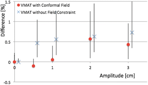

Fig. 18.4
Dose difference [%] between the calculation and the measurement as a function of the motion amplitude of the moving phantom. The measurement was conducted four times for two different plans; (1) VMAT with conformal field (red circles) and (2) VMAT without field constraint (blue crosses)
The constraint on the MLC motion, however, may significantly affect the quality of a treatment plan. In the next subsection, the plans with the MLC constraint are compared to those without the MLC constraint.
18.2.2 Constraint on MLC Motion
To reduce the interplay effect, the conformal field shape was effective, as described in the previous subsection. In inverse planning of the VMAT, the conformal-like field shape can be created by imposing a constraint on MLC motion speed; the MLC moves smoothly during VMAT delivery, so that the constraint intents to form field shapes that do not hide the target. With the MLC constraint, degrees of freedom in inverse planning are decreased. Therefore, it is informative to compare between the treatment plans with and without MLC constraint.
In the comparison between lung SBRT plans with MLC constraint and without MLC constraint, the prescribed dose was set as a D 95 prescription of 55 Gy in four fractions for planning target volume (PTV) of the lung tumour, which was created with a 5-mm isotropic margin of internal target volume (ITV) generated from 10 4D-CT sets by using a volumetric CT scanner. The single-arc VMAT using the Agility system with 6 MV was selected in the treatment plan for SmartArc in the Pinnacle v9.2 treatment planning system. The constraint on MLC motion of 0.1 cm/degree was applied in the VMAT inverse plan so that MLC had little chance to hide the PTV in beam’s eye view.
One example of the dose-volume histogram (DVH) and the corresponding dose distribution are shown in Fig. 18.5, where the solid curves denote the DVHs with an MLC constraint of 0.1 cm/degree, whereas the dashed curves denote DVHs without MLC constraint. The dose homogeneity of the plan without MLC constraint was better than the plan with MLC constraint. The dose for spinal cord was also decreased by removing the MLC constraint. On the other hand, dose conformity for PTV and the lung dose were comparable.
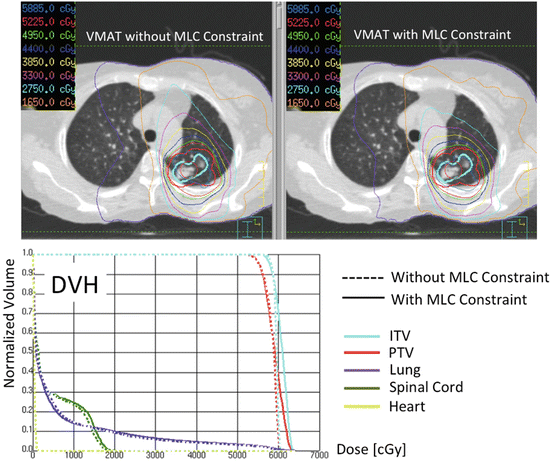

Fig. 18.5


Example of the dose distribution and DVH imposing the MLC constraint of 0.1 cm/degree
Stay updated, free articles. Join our Telegram channel

Full access? Get Clinical Tree


