Overview of Cardiovascular Magnetic Resonance Imaging
Mark Doyle
There are several important conceptual elements required to understand magnetic resonance imaging (MRI), and this broad overview seeks to introduce these and establish a framework for further in-depth studies. The topics summarized here are as follows:
Signal source
Signal characteristics
Hardware
SIGNAL SOURCE
Unlike most imaging modalities MR has several conceptual difficulties:
The origin of the signal for MR is not intuitively obvious.
The means of forming an image is not intuitively obvious.
Image contrast depends on many factors.
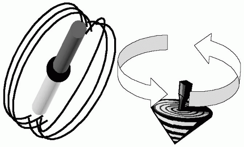
To address these we will begin with basic principles to develop an initial understanding before proceeding in later chapters into more in-depth treatments. At the most basic level, the human body is composed of approximately 70% water, which in turn is made up of an oxygen atom and two hydrogen atoms. The hydrogen atom is composed of a single proton, which has the nuclear property of spin (see Fig. 1-1). Conceptually, we can imagine the nucleus spinning just like a spinning top. Owing to the property of spin and due to the electrical charge contained within the nucleus, the proton generates a magnetic field, that is, a magnetic dipole. Because the nuclear spinning action was responsible for this property, the magnetic dipole is referred to as a spin. The property that is imaged in MRI is the distribution of spins. If a spinning top is tipped over, it will precess (i.e., slowly wobble). The wobbling action is slow relative to its spinning frequency. In summary, the physical properties required to cause a spin to precess are:
Force field (e.g., gravity)
Tipping action
This principle can be directly applied to magnetic spins in that protons are directly analogous to spinning tops. If they can be tipped over with respect to the magnetic (force) field, then they will precess. Of interest to cardiovascular magnetic resonance (CMR) is the fact that a precessing proton, due to its magnetic property, will emit an electromagnetic signal, which can be
detected and ultimately imaged. For protons the precessional frequency (ω) is in the radio frequency (RF) range, hence the sample emits an RF signal. Signal detection is accomplished by placing an electrical conductor in the vicinity of the precessing proton, which in turn induces a voltage in the conductor. This voltage is known as the electromotive force (EMF). Thereby, a conducting coil acts as the receiver for the CMR signal.
detected and ultimately imaged. For protons the precessional frequency (ω) is in the radio frequency (RF) range, hence the sample emits an RF signal. Signal detection is accomplished by placing an electrical conductor in the vicinity of the precessing proton, which in turn induces a voltage in the conductor. This voltage is known as the electromotive force (EMF). Thereby, a conducting coil acts as the receiver for the CMR signal.
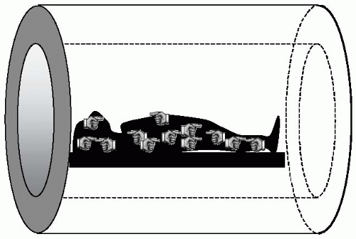
When considering magnetism and the human body, intuition does not serve us well. Intuitively, one might expect all the spins in the body (which effectively act as bar magnets) to align with an externally applied magnetic field. However, this is not the case. Quantum mechanical laws prohibit all the spins from occupying the lowest energy state (i.e., aligning with the magnetic field) (see Fig. 1-2). In essence, the body’s heat acts as an energy source that allows the spins to resist alignment with the magnetic field, and therefore the body only becomes very weakly magnetized. Further, after positioning the body in the magnet, there is still no detectable signal given off by the body. Therefore, the only thing accomplished by placing the patient in the magnet is the generation of a net magnetization vector, M0. To generate a detectable signal, M0 must be made to precess, and when precessing, it will emit an RF signal. To make M0 precess, it must be tipped from alignment with the main magnetic field B0. A key point to address now is, how to tip over the magnetization vector, M0. The magnetization vector can be tipped into the “transverse” plane by applying a small, rotating magnetic field, B1 (see Fig. 1-3). The B1 field is applied at the natural precession frequency of the spins (ω) and exploits the resonance phenomena to exert a large influence on the spin system with the expenditure of relatively little energy. The rotating B1 field is referred to as an RF pulse and has several properties:
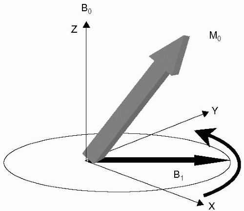 FIGURE 1-3 The direction of the main magnetic field formed by the scanner system is, by convention, referred to as the “Z” axis, or longitudinal direction. The plane transverse to the Z direction contains the “X” and “Y” axes. The net magnetization from the body is referred to as M0, and can be thought of as initially pointing along the “Z” a xis. To tip the M0 magnetization from alignment with the main magnetic field B0, a small rotating magnetic field, B1, is applied in the transverse plane. B1 is applied at the resonance frequency of the system, and consequently exerts a strong influence on M0, easily tipping it into the transverse plane. |
It is applied in the transverse plane.
It is applied at the resonance frequency.
The resonance frequency is in the RF range.
At the resonance frequency, the B1 field only has to be applied for a very short duration (˜1 ms) and consequently is referred to as the excitation RF pulse.
SIGNAL CHARACTERISTICS
There are a few more aspects of the spin system to understand before the basics of MRI can be appreciated. The net magnetization vector, M0, is composed of many individual spins and the body can be regarded as an environment with energy, collectively known as the lattice. Each spin is in a constant state of energy exchange with the lattice and with other spins. Owing to these interactions, the spin system undergoes a process known as spin relaxation. In terms of the spin system, relaxation is the process whereby the system returns to its lowest energy configuration. There are two relaxation time scales referred to as T1 and T2. To illustrate these, consider a magnetization vector, M0, tipped over by 90 degrees (i.e., into the so-called
transverse plane). The T1 relaxation process describes the process of realignment with the main magnetization vector, B0, and is referred to as spin-lattice relaxation. Similarly, the T2 relaxation describes the process of loss of coherence between individual spins, and is referred to as spin-spin relaxation. Both the T1 and T2 relaxation processes express the rate of energy exchange of individual spins, which are governed by random events and are quantized. Therefore, T1 and T2 decay curves are exponential (i.e., similar to radioactive decay). The T1 of myocardium is approximately 900 ms and its T2 is approximately 70 ms at field strength of 1.5 T. The T2 decay process is a characteristic of the material, and pure materials such as cerebrospinal fluid (CSF) tend to have long T2 values. These are essentially the values obtained under “laboratory conditions” and in practice the observed T2 decay is also dependent on the characteristics of the scanner system, such as the degree of nonuniformity of the magnetic field, which results in an apparent reduction in T2. In reality, the observed T2


transverse plane). The T1 relaxation process describes the process of realignment with the main magnetization vector, B0, and is referred to as spin-lattice relaxation. Similarly, the T2 relaxation describes the process of loss of coherence between individual spins, and is referred to as spin-spin relaxation. Both the T1 and T2 relaxation processes express the rate of energy exchange of individual spins, which are governed by random events and are quantized. Therefore, T1 and T2 decay curves are exponential (i.e., similar to radioactive decay). The T1 of myocardium is approximately 900 ms and its T2 is approximately 70 ms at field strength of 1.5 T. The T2 decay process is a characteristic of the material, and pure materials such as cerebrospinal fluid (CSF) tend to have long T2 values. These are essentially the values obtained under “laboratory conditions” and in practice the observed T2 decay is also dependent on the characteristics of the scanner system, such as the degree of nonuniformity of the magnetic field, which results in an apparent reduction in T2. In reality, the observed T2
Stay updated, free articles. Join our Telegram channel

Full access? Get Clinical Tree


