, Abas Sabouni2, Travis Desell3 and Ali Ashtari4
(1)
Department of Electrical Engineering, University of North Dakota, Grand Forks, ND, USA
(2)
Department of Electrical Engineering, Wilkes University, Wilkes-Barre, PA, USA
(3)
Department of Computer Science, University of North Dakota, Grand Forks, ND, USA
(4)
Invenia Technical Computing, Winnipeg, MB, Canada
Abstract
MWT techniques have been investigated for a long time; however, the progress in this field has been slow for a number of reasons—mainly insufficient computer power. In recent years, tremendous research has been done on fast solver computing techniques and has opened up unique opportunities for future research in MWT. In this chapter we will provide details of parallel implementation of FDTD on cluster computers.
6.1 Parallel FDTD (PFDTD)
The major time-consuming part of the proposed MWT algorithm is the forward solver which needs to run for several times (depending on the resolution). In order to overcome the runtime problem, we have proposed to employ the parallel algorithm for the FDTD forward solver.
The parallelization of FDTD is based on the distributed heartbeat algorithm. This algorithm allows separate processors to compute blocks of the problem space at each time step. The processors then exchange the boundary values to/from adjacent processors using standard message passing interface (MPI) technology [1]. The use of MPI allows for the simulation of very large problems by distributing the problem across multiple machines in addition to speeding the execution of the simulation by using more CPUs. FDTD numerical method is data parallel in nature and exhibits apparent nearest-neighbor communication pattern. Distributed memory machines, using MPI, are therefore a suitable parallel architecture for this application. FDTD code can run on a cluster which has a number of single or multiple processor nodes. MPI consists of the usual master-slave communication, where the first master process is started with identifying slave processors in which all slave nodes share a common memory. Data is distributed among the slave processes and the master collects the results. The master–slave architecture is capable of running the same code for all slave processors. This situation will give the maximum possible speedup if all the available processors can be assigned processes for the total duration of the computation. Moreover, there is minimal interaction between slave processes (embarrassingly parallel). In the single-program multiple data (SPMD) parallel programs global data is partitioned with a portion of the data assigned to each processing node.
In 2006 Yu et al. introduced three communication schemes for PFDTD [2]. The division of the computational domain is on the E along the Cartesian axis, but the three schemes differ in the way that components of E and H should be exchanged and also in the way how the processor updates the E components at the interface layer.

Fig. 6.1
(a) Spatial decomposition and (b) the data communication between two processors at the boundaries
Table 6.1
Example of different PFDTD codes with different parameters
Authors | Processor per node | Number of nodes | Maximum speedup | System |
|---|---|---|---|---|
Varadarajan-Mittra [3] | 1 | 8 | 7.06 | HP-735 |
Liu et al. [4] | 4 | 32 | 100 | Sparc II |
Tinniswood et al. [5] | 1 | 128 | 32 | IBM PS/2 |
Sypniewski et al. [6] | 4 | 1 | 2.1 | Intel PII |
Schiavone et al. [7] | 2 | 14 | 12 | Dual PII |
Guiffaut-Mahjoubi [8] | 1 | 16 | 14 | Cray T3E |
Sabouni et al. [9] | 2 | 8 | 6.25 | AMD Athlon |

Fig. 6.2
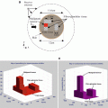
Breast phantom with skin, breast tissue, and 1 cm diameter malignant
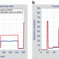
In our proposition, the computational domain is divided along the x-axis (Fig. 6.1a) of E. Given the computational domain is divided into N × N cells and p processors, then each processor receives a matrix of m × N cells where  . Each processor q (q is not equal to 1 and p, the first or last processors) shares the first and m th row of its computational domain with processors q − 1 and q + 1, respectively. Therefore, E at the interface of adjacent processors are calculated on both processors (Fig. 6.1b). The purpose of this scheme is to eliminate the communication of E and only exchange values of H to improve the computation/communication efficiency. Table 6.1 shows few examples of Different parallel FDTD codes reported in the literature. As it can be seen in this table, the maximum speedup has been increased with other PFDTD codes with the same parameters. Note that this table only provides a summary of previous work and due to the differences in the speed and type of processors it is not possible to make a fair comparison. To evaluate the efficiency of a 2D (FD)2TD using MPI, the setup in Fig. 6.2 is used. Figure 6.2 shows a breast phantom with a 12 cm diameter region and a 2 mm thickness of skin and a 1 cm diameter tumor at an off-center position. The plane wave impinges the structure at Φ = 0∘, and receivers collect the scattered fields at different angles in the far-field zone. The efficiency obtained for parallel (FD)2TD is portrayed in Fig. 6.3a with a speedup of 6.25 by 16 processors. As it can be seen in this graph, the computation time decreases when the number of processes increases. The computations were performed on the AMD machines with 8 nodes, and there are two processors in each node. Figure 6.3b shows the speedup for the FDTD algorithm when the number of processors increases. This figure shows that the increase in speedup is not linearly dependent on the number of computers. The greater the number of operating computers, the more communication time is spent. This is called “communication latency.”
 . Each processor q (q is not equal to 1 and p, the first or last processors) shares the first and m th row of its computational domain with processors q − 1 and q + 1, respectively. Therefore, E at the interface of adjacent processors are calculated on both processors (Fig. 6.1b). The purpose of this scheme is to eliminate the communication of E and only exchange values of H to improve the computation/communication efficiency. Table 6.1 shows few examples of Different parallel FDTD codes reported in the literature. As it can be seen in this table, the maximum speedup has been increased with other PFDTD codes with the same parameters. Note that this table only provides a summary of previous work and due to the differences in the speed and type of processors it is not possible to make a fair comparison. To evaluate the efficiency of a 2D (FD)2TD using MPI, the setup in Fig. 6.2 is used. Figure 6.2 shows a breast phantom with a 12 cm diameter region and a 2 mm thickness of skin and a 1 cm diameter tumor at an off-center position. The plane wave impinges the structure at Φ = 0∘, and receivers collect the scattered fields at different angles in the far-field zone. The efficiency obtained for parallel (FD)2TD is portrayed in Fig. 6.3a with a speedup of 6.25 by 16 processors. As it can be seen in this graph, the computation time decreases when the number of processes increases. The computations were performed on the AMD machines with 8 nodes, and there are two processors in each node. Figure 6.3b shows the speedup for the FDTD algorithm when the number of processors increases. This figure shows that the increase in speedup is not linearly dependent on the number of computers. The greater the number of operating computers, the more communication time is spent. This is called “communication latency.”
Stay updated, free articles. Join our Telegram channel

Full access? Get Clinical Tree


