Platforms for Image-guided and Adaptive Radiation Therapy
Warren Kilby
Calvin R. Maurer Jr.
Nicole Walls
Isabell Schwenkert
Kevin J. Brown
Christopher Amies
Ali Bani-Hashemi
Burkhardt Groh
Thomas Tuecking
Kenneth J. Ruchala
Weiguo Lu
Gustavo H. Olivera
Thomas R. Mackie
Peter Munro
Radiation therapy is a technology-intense field of medicine. Image-guided adaptive radiation therapy (IGART) represents a half century of technologic developments in sciences, engineering, and medicine. The medical equipment industry is an integral part of the field of radiation oncology and plays an indispensable role in the development and evolution of IGART. In this chapter, some leading companies in IGART are invited to provide objective descriptions of their research and development efforts. It is hoped that the readers will gain useful insight and knowledge from the industrial perspectives.
CYBERKNIFE ROBOTIC RADIOSURGERY SYSTEM
The CyberKnife Robotic Radiosurgery System (Accuray Incorporated, Sunnyvale, Calif) is designed to deliver radiosurgery, also known as stereotactic body radiation therapy for extracranial applications,1 generally using one to five treatment fractions, to targets located anywhere in the body. Clinical practice with the CyberKnife System demonstrates its adoption for whole-body applications, with major treatment indications including intracranial lesions,2, 3, 4, 5, 6, 7 spinal lesions,3,8, 9, 10, 11, 12 lung tumors,13, 14, 15, 16, 17 and prostate cancer.18, 19, 20 The two main technical requirements associated with this overall design are as follows:
The dose distribution should be highly conformal to the target volume, with steep dose gradients in all directions away from the target volume.
Treatment beams should be aligned and delivered with high accuracy to the target volume throughout every treatment fraction.
The first requirement ensures that the dose delivered to all normal tissues and organs at risk around the planning target volume (PTV) is minimized. The second requirement enables the PTV to be defined with a minimal margin around the clinical target volume (CTV) and thus include only a minimum of normal tissue. The following sections describe the CyberKnife System design, with particular attention to how this design fulfills these two technical requirements.
CYBERKNIFE SYSTEM OVERVIEW
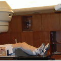
The CyberKnife System (Fig. 1.6) consists of several key subsystems: a robotic manipulator; a miniature lightweight linear accelerator (linac); an x-ray imaging system; a stereo camera system, which is part of the Synchrony Respiratory Tracking System; and a treatment table. The CyberKnife System moves the radiation beam by physically repositioning the radiation source. The linac is mounted to the robotic manipulator, which has six degrees of freedom, allowing it to position the linac within a large three-dimensional (3D) workspace around the patient with high accuracy. The x-ray image guidance system is used to align each treatment beam to the target volume. For tumors that move with respiration, the Synchrony System tracks the tumor and aligns the treatment beam dynamically with the target. Each of these main subsystems is described in detail below.
Robotic Manipulator. The KR240-2 (Series 2000) robotic manipulator (Kuka Roboter GmbH, Augsburg, Germany) used in the CyberKnife System has a manufacturer specification for position repeatability of better than 0.12 mm. High accuracy is achieved by determining and compensating for position offsets in a calibration process. The use of the robotic manipulator removes any isocentric constraint on the treatment beams, which allows each treatment beam to be directed at a unique point in space. The robotic manipulator also removes any coplanar constraint on the beam geometry, which enables routine treatment delivery using a large number of noncoplanar beams without any need to reposition the patient during treatment. The robotic manipulator allows for compensation of changes in the target volume position and orientation during
treatment by adjusting the beam position and orientation rather than by moving the patient. This improves the accuracy of the alignment process because the manipulator can be moved with greater precision than the patient, who cannot be considered to act as a rigid body attached to the couch. Furthermore, the robotic manipulator allows for real-time tracking of tumors that move with respiration; alignment of each treatment beam with the moving target is maintained in real time by moving the beam dynamically with the target.
treatment by adjusting the beam position and orientation rather than by moving the patient. This improves the accuracy of the alignment process because the manipulator can be moved with greater precision than the patient, who cannot be considered to act as a rigid body attached to the couch. Furthermore, the robotic manipulator allows for real-time tracking of tumors that move with respiration; alignment of each treatment beam with the moving target is maintained in real time by moving the beam dynamically with the target.
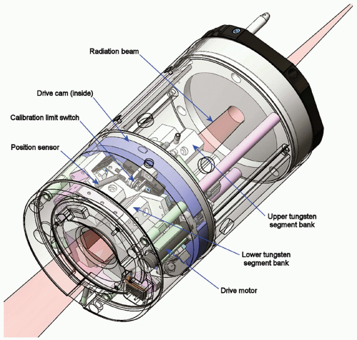
Linac. The CyberKnife System’s miniature lightweight linac uses an X-band cavity magnetron and a standing wave, side-coupled accelerating waveguide to produce a 6-MV x-ray treatment beam with a dose rate of up to 800 cGy per minute (defined at a depth in water of 1.5 cm and a distance of 80 cm from the x-ray target on the central axis of a 6-cm diameter field). The compact design allows a configuration that does not require a bending magnet. The linac head also does not include a beam flattening filter. Secondary beam collimation is provided using either fixed circular collimators or the Iris Variable Aperture Collimator (Fig. 19.1). Twelve fixed circular collimators, with diameters in the range 0.5 to 6 cm (projected at 80-cm distance), are available. Any three collimators can be used during a single treatment, and these can be fitted manually or automatically using the Xchange Robotic Collimator Changer, which enables the manipulator to swap collimators without any manual intervention. The Xchange system also allows a fixed collimator to be swapped for the Iris Collimator. The Iris Collimator allows the same set of 12 circular field sizes to be achieved with a single variable aperture and therefore provides the flexibility to apply any field size at each beam position without the need to swap collimators during treatment.
X-ray Imaging System. The CyberKnife System’s targeting system uses an orthogonally mounted pair of x-ray tubes and image detectors. Two diagnostic x-ray sources are mounted to the ceiling of the CyberKnife treatment room and illuminate two x-ray detectors by projecting square x-ray fields at 45 degrees from vertical. At the imaging center, which is the point where the central axes of these beams intersect, the x-ray field size is approximately 15 × 15 cm. The flat panel x-ray detectors, which are mounted flush with the floor, consist of cesium-iodide scintillator deposited directly on amorphous silicon photodiodes and generate high-resolution digital images (1,024 × 1,024 pixels with 16-bit resolution). The x-ray sources and detectors are rigidly fixed, and their projection camera geometry is calibrated and known with high accuracy in the treatment room coordinate system.
Stereo Camera System. The positions of three external optical markers, which are attached to a vest worn by the patient during treatment, are measured continuously with a stereo camera system that is mounted on a boom arm attached to the ceiling of the treatment room. In combination with the x-ray image guidance system, this enables the robotic manipulator to track tumors that move with respiration in real time. The Synchrony Respiratory Tracking System is described in more detail later in this chapter.
At the start of a CyberKnife treatment, the x-ray image-guided tracking system is used to align the patient with the assistance of an adjustable treatment table. Both a five-axis table and a six-axis RoboCouch Patient Positioning System,
shown in Figure 1.6, are available. After an initial alignment performed by the operator, computer algorithms automatically compare the projection x-ray images of the target region with the patient’s treatment planning computed tomography (CT) scan. Image registration methods are used to compute the 3D spatial coordinates (position and orientation) of the target. The image registration is based on either the target anatomy visualized within the images or an internal surrogate structure fixed relative to it. The computed coordinates are used to determine translational and rotational corrections. These corrections are relayed to the robotic manipulator and used to automatically compensate for small target movements by repositioning the linac such that it has the same beam alignment with respect to the target volume during treatment delivery as was simulated during treatment planning.
shown in Figure 1.6, are available. After an initial alignment performed by the operator, computer algorithms automatically compare the projection x-ray images of the target region with the patient’s treatment planning computed tomography (CT) scan. Image registration methods are used to compute the 3D spatial coordinates (position and orientation) of the target. The image registration is based on either the target anatomy visualized within the images or an internal surrogate structure fixed relative to it. The computed coordinates are used to determine translational and rotational corrections. These corrections are relayed to the robotic manipulator and used to automatically compensate for small target movements by repositioning the linac such that it has the same beam alignment with respect to the target volume during treatment delivery as was simulated during treatment planning.
During treatment, x-ray image acquisition and target localization are repeated periodically (typically about once every 30 to 120 seconds). As described earlier, the robotic manipulator compensates for small translations and rotations. Large translations and rotations automatically pause treatment and prompt the operator to reposition the patient before proceeding. The patient repositioning can be performed automatically using the RoboCouch table or automatically using the five-axis table for all translations and rotations except the yaw angle. By repeating the process of x-ray image acquisition and target localization throughout every fraction, the system is able to track, detect, and correct for intrafraction motion of the target volume. Continual image guidance eliminates the need for an external stereotactic alignment frame (and the associated assumption of a fixed relationship between the external frame and the internal target volume) and does not require an assumption of zero intrafraction motion after initial patient setup.
TREATMENT PLANNING
Treatment planning is performed using the dedicated Multiplan Treatment Planning System, which is integrated with the treatment delivery system via a data management server. Treatment plans are constructed using the following steps.
Multimodality Image Registration and Volume Definition. All CyberKnife treatment plans require a volumetric CT scan for use by the x-ray image-guided tracking system and for construction of the 3D patient model needed to simulate the noncoplanar treatment beam geometry. Up to three additional 3D image sets can be loaded simultaneously and registered to this CT scan (e.g., magnetic resonance imaging [MRI], positron emission tomography [PET], 3D rotational angiography, or additional CT images). Image registration and fusion can be performed by using an algorithm that maximizes the mutual information between the two images being registered without requiring any preprocessing or segmentation of the images,21,22 by aligning manually identified anatomic landmarks or semi-automatically determined fiducial marker positions, or by manually aligning the two images. Target volumes, organs at risk, and other structures can be defined on any of these images in any of the cardinal image planes.
Beam Geometry Definition. The CyberKnife System’s robotic manipulator allows an infinite number of possible beam directions. The beam geometry is constrained to a practical size during treatment planning by defining a limited number of candidate beams. Each candidate beam is specified by a vector that links a source point to a direction point. The source point is the position within the linac head of the x-ray target from which the photons exit. The direction point is usually a point within the target volume. Discrete sets of source points (linac x-ray target positions) are predefined at nominal distances of 65 to 100 cm from the imaging center. Each source position is called a node, and a set of source positions is called a path set. A path set is the set of positions the linac can visit during treatment. Different path sets, which typically contain approximately 100 nodes, are constructed to provide the largest possible range of noncoplanar beam directions
for intra- and extracranial treatment sites. The appropriate path set for each patient is selected manually. Direction points are determined automatically based on the user-selected targeting mode, which is either isocentric or nonisocentric. Isocentric targeting allows the user to position one or more discrete points, or pseudo-isocenters, within the patient model, resulting in a generated set of beam candidates with one beam from each node (source point) to each pseudo-isocenter (direction point). Nonisocentric targeting generates a large number of direction points (typically 1,000 to 6,000 depending on collimation and optimization algorithm options) semi-randomly within the target volume and distributes these uniformly among the nodes to form the candidate beam set. The user selects between one and three fixed collimator sizes or between one and 12 Iris Collimator field sizes, which are assigned to subsets of the candidate beam set. The isocentric targeting option produces an overall dose distribution comprised of approximately spherical dose clouds around each pseudo-isocenter similar to those in other radiosurgery systems using circular collimators. The nonisocentric targeting option represents a very different treatment geometry that is more similar to those achieved using multiple pencil beams. From a single node, a modulated fluence pattern can be delivered using multiple beams directed at unique points within the target volume, each of which has an optimized field size and beam weight.
for intra- and extracranial treatment sites. The appropriate path set for each patient is selected manually. Direction points are determined automatically based on the user-selected targeting mode, which is either isocentric or nonisocentric. Isocentric targeting allows the user to position one or more discrete points, or pseudo-isocenters, within the patient model, resulting in a generated set of beam candidates with one beam from each node (source point) to each pseudo-isocenter (direction point). Nonisocentric targeting generates a large number of direction points (typically 1,000 to 6,000 depending on collimation and optimization algorithm options) semi-randomly within the target volume and distributes these uniformly among the nodes to form the candidate beam set. The user selects between one and three fixed collimator sizes or between one and 12 Iris Collimator field sizes, which are assigned to subsets of the candidate beam set. The isocentric targeting option produces an overall dose distribution comprised of approximately spherical dose clouds around each pseudo-isocenter similar to those in other radiosurgery systems using circular collimators. The nonisocentric targeting option represents a very different treatment geometry that is more similar to those achieved using multiple pencil beams. From a single node, a modulated fluence pattern can be delivered using multiple beams directed at unique points within the target volume, each of which has an optimized field size and beam weight.
Dose Calculation. Two dose calculation algorithms are available: ray tracing and Monte Carlo dose calculation. The ray tracing algorithm is a fast method based on measured beam data. Heterogeneity correction is performed using the effective path length method, and obliquity correction is performed by casting multiple rays within each beam. The Monte Carlo dose calculation algorithm uses a measurement-based virtual source representation of the linac head to simulate each treatment beam and performs treatment plan dose calculations in generally <5 minutes for a calculation uncertainty of 2%. This algorithm has been described by Ma et al.,23 and its dose calculations have been compared against measurements in heterogeneous phantoms.24, 25, 26 The Monte Carlo dose calculation algorithm can be used to provide either a retrospective dose calculation for an existing treatment plan or the input dose calculation for a candidate beam set to be used during subsequent plan optimization. Therefore, this Monte Carlo implementation allows both the dose calculation and optimization convergence errors to be minimized for any treatment plan where the ray tracing algorithm does not provide sufficient calculation accuracy.
Plan Optimization. Forward planning can be performed for isocentrically targeted beams, whereby all beams directed at each pseudo-isocenter are evenly weighted. Inverse planning can be performed for both isocentrically and nonisocentrically targeted beams using Simplex, Iterative, or Sequential Optimization algorithms. Perhaps the most powerful method is the Sequential Optimization algorithm, which allows the tradeoffs between conflicting cost function terms to be explicitly investigated and Pareto efficient solutions to be obtained quickly.27 Inverse planning typically reduces the candidate beam set down to 75 to 200 beams with non-zero monitor unit (MU) settings, and therefore, along with optimizing beam weights, this method also selects the optimal beam vectors and beam sizes from among those contained within the candidate beam set.
In summary, the robotic manipulator, variable beam collimation, and treatment planning system algorithms make possible the generation of treatment plans that combine a large number of noncoplanar, isocentrically or nonisocentrically targeted beams. Treatment plans are based on an accurate dose calculation even in heterogeneous situations (e.g., lung tumors), and the planning process automatically generates the optimum set of beam weights, directions, and field sizes in order to achieve the desired dose distribution. This combination enables treatment plans to be generated with highly conformal dose distributions and steep dose gradients in all directions, as required for stereotactic radiosurgery. Example CyberKnife treatment plans are shown in Figure 19.2. The next sections describe in more detail how the x-ray image guidance and respiratory motion tracking systems enable these treatment plans to be delivered with very high accuracy and, thus, the CTV-to-PTV margin to be minimized.
X-RAY IMAGE GUIDANCE SYSTEM
CyberKnife treatments rely on x-ray image guidance to align each treatment beam to the target volume. No use is made of an external stereotactic frame or skin marks, and therefore, there is no dependence on a fixed geometric relationship between these external markers and the internal target anatomy. Instead, the stereotactic coordinate system is defined by the target anatomy itself or an internal surrogate fixed relative to it. This frame of reference at the time of treatment is aligned to the coordinate system defined during treatment planning by comparing the projection x-ray image pairs of the target region acquired during treatment with the patient’s treatment planning CT image. In particular, the target pose (position and orientation) is determined using image registration. Synthetic x-ray images, commonly referred to as digitally reconstructed radiographs (DRRs), are generated from the treatment planning CT image by casting rays through the CT image using the known x-ray imaging system geometry to simulate the x-ray image formation process. Registrations between an x-ray image and the corresponding DRR image are performed independently for each x-ray image within the orthogonal pair. The resulting transformations for the two x-ray images are then combined and converted to a 3D transformation by geometric backprojection. The 3D transformation is used to determine translational and rotational corrections that are relayed to the robotic manipulator, which compensates for small movements of the target by realigning the radiation beam to maintain the same beam alignment with respect to the target as was simulated during treatment planning. Registration-based target localization is called tracking because it is repeated periodically during treatment. The registration process is performed automatically within 1 to 2 seconds by the treatment delivery system. The tracking result is reported to the user and can be verified manually using various tools such as linked cross-hair cursors in the DRR and treatment x-ray images and combinations of the DRR and treatment x-ray images produced by addition or subtraction of corresponding pixel values.
The registration process is performed using one of four different methods depending on the target anatomy. All of these tracking methods involve the following sequence: acquire x-ray images, localize the target by performing image registration of the acquired images to the DRR images, determine the translational and rotational corrections resulting from the transformation, adjust the beam position to maintain the same beam alignment with respect to the target volume during treatment delivery as was simulated during treatment planning, and deliver the beam. This sequence is performed during patient setup and is repeated periodically throughout each treatment fraction. The benefit of this continual image guidance is that there is no reliance on the target volume remaining static after the initial pretreatment alignment procedure. Each of the four tracking methods is described in detail below.
Six-Dimensional (6D) Skull Tracking. This tracking method can be used for intracranial target volumes as well as for head and neck target volumes that are considered to be fixed relative to the skull. Image registration is performed using high-contrast bone information contained within the entire field of view. Each 2D registration between an x-ray image and its corresponding DRR image is performed in multiple stages, using two image similarity measures and several search methods. The resulting 2D transformations for each orthogonal projection are then combined and backprojected to determine the 3D rigid transformation that aligns the position and orientation of the skull in the treatment planning CT image with the treatment delivery coordinate system. The algorithm is described in detail by Fu and Kuduvalli.28 End-to-end testing, which consists of scanning, treatment planning, and treatment delivery with anthropomorphic phantoms, has consistently shown the 3D total system error to be <1 mm for this tracking method.28 The total system error, which is defined as the distance between the centroids of the planned and delivered dose distributions, represents all possible errors in the treatment planning delivery process, including errors in the tracking system, the CT scanner, the treatment planning software, the robotic manipulator, and the linac.
Xsight Spine Tracking. This tracking method can be used for target volumes located anywhere in the spine or other targets that are located near the spine and considered to be fixed relative to the spine. As with the skull tracking method, image registration is based on high-contrast bone information (skeletal structure) within the images. However, there are several substantial differences from the skull tracking method. In spine tracking, image processing filters are applied to enhance the skeletal structures in both the DRR and the treatment x-ray images. This improves estimation of local displacements for these structures. Optionally, the DRRs can be generated by restricting attenuation to voxels within a region surrounding the spine. These DRRs represent only spine anatomy; they do not exhibit image artifacts from tissue motion during image acquisition or from nonspinal bony anatomy such as the rib cage. Registration is performed in a region of interest (ROI) that includes the anatomy to be treated. The position and size of the ROI are manually defined and generally include the vertebra of interest plus the two adjacent vertebrae. The local displacement vector that aligns a point in the DRR image with the corresponding point in the x-ray image is estimated at each node point in a grid or mesh laid over the ROI. A small region or block surrounding the node point in the DRR image is compared with regions in the x-ray image. The intensity pattern in this small region represents local skeletal structure. Block matching, which is essentially the estimation of local displacements of skeletal structure, is performed in a multiresolution approach to increase efficiency and robustness. The position (translation) and orientation (rotation) of the skeletal anatomy, and thus the target, are computed from the resulting local displacement fields between the x-ray image and the DRR image. Details of this algorithm have been described elsewhere.29, 30, 31 End-to-end tests performed using this tracking method have also consistently shown the 3D total system error to be <1 mm.31,32
Xsight Lung Tracking. This tracking method can be used for tumors located within the lung. The general lung tracking approach differs from other tracking methods used in the CyberKnife System in that patient alignment and tumor tracking are performed in two stages rather than one. Xsight Lung Tracking begins with global patient alignment, including both position and orientation, using the region of the spine nearest the lung tumor. This patient alignment step is performed using the Xsight Spine Tracking method described earlier. After the patient is globally aligned, the treatment couch moves the patient from the spine alignment center to the tumor treatment center (the two centers are defined during treatment planning). After this movement, the tumor will be close to the reference position around which it will move as the patient breathes. Direct tumor tracking is performed by image registration of the tumor region in the DRRs to the corresponding region in the treatment x-ray images. Specifically, the image intensity pattern of the tumor region in the DRR is matched to the most similar region in the x-ray image. A matching window for the tumor is defined based on the tumor silhouette in each projection. The registration process is conducted separately for each projection, resulting in 2D translations for each projection; the 3D tumor translation is determined by backprojection of the 2D translations. This image registration process requires that the tumor be visible in the x-ray images; that is, the image intensity pattern of the tumor must be distinguishable from other objects in the image, which requires the tumor to have sufficient contrast relative to the surrounding region. The two primary factors that determine tumor visibility are tumor size (which influences contrast) and tumor location (which can influence contrast if the tumor is superimposed in the x-ray image on radiopaque structures such as the spine and mediastinum). Observation and analysis of clinical image data for more than 50 patients previously treated with the CyberKnife System indicate that many reasonably large tumors (>15 mm) located in the peripheral and apex lung regions are visible in the orthogonal x-ray images acquired by the CyberKnife System. This analysis suggests that the Xsight Lung Tracking system may be appropriate for treatment of approximately 20% to 40% of CyberKnife lung patients. The treatment planning system has an added feature for Xsight Lung Tracking that provides a quality review of the tracking DRRs to help confirm patient eligibility for lung tracking. For targets that move with respiration, this tracking method can be combined with the respiratory tracking system described in a later section. The algorithm is described in detail by Fu et al.,33 who also present results
of end-to-end testing using an anthropomorphic motion phantom and a retrospective analysis of clinical image data. The 3D total system error measured with the anthropomorphic motion phantom was 0.9 mm without tumor motion and 1.1 mm with 30-mm superior-inferior motion amplitude. Using clinical image data, the tracking system error component of the total system error, which is equivalent to the tumor target registration error, was found to be 1.1 ± 0.2 mm (mean ± standard deviation [SD]) for data from 10 patients who underwent CyberKnife treatment for lung lesions using implanted fiducial markers. The fiducial-based tracking result was used as the reference transformation to compute the lung tracking error. In the worst case, in which all errors measured in the phantom studies are due to non-tracking system errors, the experimental (nontracking) and clinical (tracking) errors add in quadrature, and the clinical total system error would be 1.5 mm for tracking a moving lung tumor.
of end-to-end testing using an anthropomorphic motion phantom and a retrospective analysis of clinical image data. The 3D total system error measured with the anthropomorphic motion phantom was 0.9 mm without tumor motion and 1.1 mm with 30-mm superior-inferior motion amplitude. Using clinical image data, the tracking system error component of the total system error, which is equivalent to the tumor target registration error, was found to be 1.1 ± 0.2 mm (mean ± standard deviation [SD]) for data from 10 patients who underwent CyberKnife treatment for lung lesions using implanted fiducial markers. The fiducial-based tracking result was used as the reference transformation to compute the lung tracking error. In the worst case, in which all errors measured in the phantom studies are due to non-tracking system errors, the experimental (nontracking) and clinical (tracking) errors add in quadrature, and the clinical total system error would be 1.5 mm for tracking a moving lung tumor.
Fiducial Marker Tracking. This tracking method can be used for soft tissue target volumes that are not fixed relative to the skull or spine (e.g., prostate, pancreas, liver), including lung tumors for which the lung tumor tracking method is unsuitable (i.e., tumors that are not clearly visible in the x-ray and DRR images, as can be the case for small or centrally located tumors). For this technique, radiopaque fiducial markers, which serve as radiographic landmarks, are implanted in or adjacent to the lesion being treated. Because implantation takes place before the acquisition of the treatment planning CT image and because the fiducial markers have a fixed relationship to the lesion that they are implanted in or adjacent to, the fiducials provide an internal frame of reference. Cylindrical gold seeds are often used for fiducial markers, with typical dimensions of 0.8 to 1.2 mm in diameter and 3 to 6 mm in length. Fiducial markers are often implanted percutaneously under image guidance. Implantation in the lung can be performed bronchoscopically.34,35 Between three and five fiducial markers are typically implanted, and in most instances, the treatment planning CT scan is acquired a week or more after implantation to allow the fiducial marker positions to stabilize. Fiducial markers are then identified in the planning CT scan, and therefore, their positions are known in the DRR images. Image registration is based on alignment of the known fiducial marker positions in the DRRs with the marker locations extracted from the treatment x-ray images. This process is described in detail elsewhere.36, 37, 38 An assessment of potential fiducial marker migration is checked by determining individual marker misalignment after registration, allowing individual fiducial markers to be omitted from the registration calculation if necessary. As with the other tracking methods, the 3D total system error associated with this tracking method has been consistently reported to be <1 mm for static targets.39 For targets that move with respiration, fiducial marker tracking can be combined with the Synchrony Respiratory Tracking System described in a later section.
ASSESSMENT OF INTRAFRACTION MOTION
In addition to enabling intrafraction alignment correction, the x-ray image guidance system provides a powerful tool for studying intrafraction motion using tracking information recorded during each treatment. Hoogeman et al.40 recently analyzed tracking information stored in treatment log files to study the intrafraction target volume motion of 57 patients treated for intracranial, head and neck, and spinal indications. All patients were fitted with noninvasive immobilization equipment including carefully fitted thermoplastic masks and head rests (for intracranial, head and neck, and upper spine targets) and vacuum formed bags (for spine targets). Spine patients were treated in either a supine or prone position. Alignment x-ray images were acquired during CyberKnife treatment with a typical frequency of once every 1 to 2 minutes, and from these data, the uncorrected intrafraction motion (i.e., assuming that alignment corrections were not performed using the CyberKnife System) was calculated over 15-minute periods. The maximum translational offset observed in any direction over a 15-minute period was 3.8, 4.3, and 12.3 mm for the intracranial, supine spine, and prone spine cases, respectively. Respiratory motion was noted as the cause of the larger offsets observed for the prone patients. Considering only the first two patient groups, the systematic 3D translational offset—quantified as two SDs above the population mean systematic translational offset—over a 15-minute period was 1.6 and 2.4 mm for the intracranial and supine spine groups, respectively. These offsets were observed to increase linearly with time and therefore would be approximately 3.2 and 4.8 mm for intracranial and supine spine cases, respectively, over a period of 30 minutes. These are the systematic offsets due to intrafraction motion that would be expected within a patient population for a treatment technique in which alignment was performed using pretreatment imaging and the gap between image acquisition and the end of treatment was 15 to 30 minutes. These values do not include the effect of systematic rotational offsets. For both groups, the systematic rotational offset observed over 15 minutes was 0.6 to 1.0 degrees (two SDs) in each rotation direction, again increasing linearly with time. By comparison, the systematic 3D translational offset observed over the typical CyberKnife interimage period of 1 to 2 minutes was <0.2 and <0.4 mm (two SDs) for intracranial and supine spine cases, respectively, and the systematic rotational offset was <0.15 degrees (two SDs) in each rotation direction for both groups. In summary, the residual alignment error over the interval between alignment corrections for cranial and spine patients during CyberKnife treatment is small. Of course, this analysis does not apply to targets that move with respiration. For such targets, an alternative tracking method is used, which is described in the following section.
SYNCHRONY RESPIRATORY TRACKING SYSTEM
Tumors in the thorax and abdomen move during respiration. One way to manage respiratory motion is to dynamically move or shape the radiation beam to follow the tumor’s changing position, an approach that is often referred to as real-time tracking. The Synchrony Respiratory Tracking System, which is an integrated subsystem of the CyberKnife System, is a realization of real-time tracking for tumors that move with respiration. Alignment of each treatment beam with the moving target is maintained in real time by moving the beam dynamically with the target. Continuous real-time tracking and treatment maintains a 100% duty cycle for efficient dose delivery. The patient breathes normally throughout the treatment without the need for breath-holding, which can be physically demanding for
elderly patients or patients with compromised pulmonary capacity, as is often the case for patients with lung cancer.
elderly patients or patients with compromised pulmonary capacity, as is often the case for patients with lung cancer.
The primary concept in the Synchrony system is a correlation model between internal tumor position and external marker position. To reduce radiographic imaging exposure, episodic radiographic imaging is combined with continuous measurement of an external breathing signal.41 At the start of treatment, the internal tumor position is determined at multiple discrete time points by acquiring orthogonal x-ray images and using either the fiducial marker or Xsight Lung tracking method, as described earlier. A linear or quadratic correlation model is then generated by fitting the 3D internal tumor positions at different phases of the breathing cycle to the simultaneous external marker positions. An important feature of this method is its ability to fit different models to the inhalation and exhalation breathing phases. During treatment, the internal tumor position is estimated from the external marker positions using the correlation model, and this information is used to move the linac dynamically with the target. The model is checked and updated regularly during treatment by acquiring additional x-ray images.
The Synchrony system uses external optical markers to provide a breathing signal. Three optical markers are attached to a snugly fitting vest that the patient wears during treatment. The optical marker positions correspond to the chest wall position. Light-emitting diodes (LEDs) transmit light through optical fibers that terminate at the cylindrical optical marker. This approach was chosen over directly attaching LEDs to the vest to avoid the presence of copper wire in the x-ray images. The optical markers are sequentially strobed, and a stereo camera system, which consists of three linear charge-coupled device (CCD) detector arrays, measures the 3D marker positions continuously at a frequency of approximately 30 Hz.
A schematic block diagram of respiratory motion tracking in the Synchrony system is shown in Figure 19.3. There is a separate correlation model for each external marker. The external marker positions are measured continuously and input into the corresponding correlation models. Each model provides an estimate of the target position from the external marker variable. The individual estimates are averaged to get the final estimate of the target position. This value represents the position of the target at the present time. Ideally, this value can be sent to the robotic manipulator as a position command without any delay. However, communication latencies, along with robotic manipulator and linac inertia, cause delays; if the present time estimate of the target position is sent to the robot, there will be a lag in the robot manipulator’s motion. A predictor is used that will compensate for the delays in the system using the history of the target movement. The predictor is adaptive and is designed to respond quickly to changes in the breathing pattern and target movement. Finally, the output of the motion predictor is passed through a smoothing filter before it is sent to the robot as a position command. Details of the Synchrony system are described in Sayeh et al.42
Inter- and intrafraction changes in position and motion are common and well known.43, 44, 45 A correlation model is generated at the beginning of every treatment, which addresses the issue of interfraction variability. However, the target position and motion typically change during the treatment. This could be caused by gradual patient relaxation throughout the treatment period. In the lung, this could be attributed to gravity action on compliant lung tissue. Thus, it is important to regularly check and update the correlation model during treatment. This is accomplished in the Synchrony system by acquiring additional x-ray images. In practice, additional x-ray images are typically acquired every 1 to 2 minutes. When a new x-ray image pair is acquired, the time of the image acquisition is used to find the corresponding positions of the external optical markers, which are used to compute the predicted target position from the correlation model. This information is first used by the target localization software to provide a better initial estimate for the automatic detection of the target position in the x-ray images. The model-based predicted target position is compared with the image-based actual position. The correlation model error, which is the distance between the predicted and actual positions, is computed and displayed in a graph including the previous correlation model errors. If the error is larger than a predefined value, the treatment is paused, and the user is informed about the discrepancy; the model can then be checked with additional x-ray image acquisitions or completely regenerated. If the correlation model accuracy is adequate, the newly acquired data point is used to update the model as described in the previous section. Thus, the correlation model adapts to gradual changes in target position and motion during treatment. The maximum number of data points for a model is 15. If there are already 15 data points when a model is updated, the most recently acquired data point is added, and the oldest data point is deleted (a first-in, first-out strategy).
Reported experimental measurements and retrospective analysis of clinical data demonstrate that the accuracy of Synchrony tracking is approximately 1.5 mm. The first reported study of the Synchrony Respiratory Tracking System was performed in 2004 by physicists at three CyberKnife centers.46 They performed end-to-end testing and computed total system error as described previously in the discussion of other tracking methods. Programmable motion tables were used to simulate respiratory motion of the object and the external optical markers. The motion patterns reproduced extreme examples of the motion measured by real-time fluoroscopic examination of lung tumors with implanted fiducial markers.44,45 Specifically, the amplitude of motion was 25, 8, and 3 mm for superior-inferior, anterior-posterior, and left-right directions, respectively; the motion pattern was a sin4(ωt) waveform; the period was 3.6 seconds; and the phase difference between the object and marker motions was 0, 15, and 30 degrees for different experiments. Relative to a static treatment case, the mean error observed during treatment with the Synchrony system across all motion patterns was 0.7 ± 0.3 mm.
Improvements have been made to the Synchrony system since this study was conducted, including the introduction of nonlinear correlation models, which improve the tracking accuracy for motions involving non-zero phase differences. A more recent study performed using nearly identical motion amplitudes, waveforms, and phase differences but with an improved version of the Synchrony system reported total system errors of <1 mm for all measurements made using respiratory motion tracking.47 Accuray recently released the Synchrony Motion Table, which was developed for performing quality assurance of Synchrony respiratory motion tracking. The motion table waveform is approximately |sin3(ωt)|, with a single linear axis target platform excursion of 25 mm and a platform for the external optical markers that moves orthogonal to the target motion through a distance of approximately 10 mm. The phase difference between the target and marker motions is fully adjustable from 0 to 180 degrees. A multi-institutional study of Synchrony respiratory motion tracking accuracy is currently underway using this quality assurance motion table. The total system error (distance between the centroids of the planned and delivered dose distributions) reported in preliminary results from three of the six participating centers was <0.5 mm for phase differences of 0, 10, and 20 degrees and <1 mm for 30 degrees.48
In addition to causing a shift in the centroid of the dose distribution, respiratory motion may blur the dose distribution (i.e., reduce the steepness of the dose gradient around the target). This effect was studied using the technique described earlier. The distance between the 20% and 80% isodose lines (normalized to maximum dose) was measured in the superior-inferior direction (the axis of greatest motion) at the edges of the target.47 Motion-induced blurring was quantified by the change in the 20% to 80% distance for treatments with and without motion. When using the Synchrony system to track a target and correct a target with linear motion, no additional blurring resulted; tracking and correcting a target with extreme nonlinear correlation (30-degree phase difference between object and external optical marker motions) resulted in 1 mm of blurring. This compares to dose blurring of >8 mm when no respiratory tracking was used. The CyberKnife team at Erasmus Medical Center-Daniel den Hoed Center, Rotterdam, the Netherlands, conducted a similar experiment using a treatment plan with far greater isodose line complexity than typically encountered clinically. Treatment was delivered using simulated respiratory motion with and without Synchrony respiratory tracking; the amplitude of motion was 20 mm, the motion pattern was a sin2(ωt) waveform, and the period was 7 seconds. The results show isodose line agreement to be generally better than 1 mm, with a maximum displacement of 2 mm (Fig. 19.4).
Most of the reported testing of the Synchrony system has been performed using motion phantoms, but there has also been some retrospective analysis of clinical data. As mentioned previously, during a CyberKnife radiosurgery treatment with the Synchrony system, the correlation model is checked and updated regularly by acquiring additional x-ray images. The correlation model error, which is the distance between the model-based predicted and image-based actual positions, is computed, displayed, and stored in a log file. This error is a measure of the accuracy of Synchrony tracking in an actual clinical application. In one report, the log files from 14 patients treated at three CyberKnife centers were collected and analyzed.49 The average of 510 correlation error values contained in these log files was 1.4 ± 1.0 mm (mean ± SD). A linear correlation model was used for all cases. More recently, Seppenwoolde et al.50 examined the correlation model error for eight lung cancer patients treated with respiratory gating.51 All of these patients had simultaneous and continuous recordings of internal tumor and external marker positions. These data were used to simulate a CyberKnife treatment with Synchrony tracking. The continuous internal tumor position data were used to compute the continuous correlation model error. The use of the linear correlation model achieved low correlation model error in all cases. In the cases with hysteresis, the quadratic model provided some additional improvement in tracking accuracy. The authors concluded that the “combined use of internal and external markers allow the robot to accurately follow tumor motion even in the case of irregularities in breathing patterns.”50 The chest wall and internal target motion for two of these patients was replicated using a sophisticated respiratory motion phantom.52 One patient exhibited a significant phase difference between chest wall and tumor motion, and both patients exhibited irregular motion amplitude, period, and baseline. For each patient, a treatment plan was delivered twice, once to a static phantom and once to the phantom during patient-specific motion with Synchrony respiratory tracking. The dose distributions measured using radiochromic dosimetry film for the static and moving treatment cases were compared using a Gamma analysis with a pass criterion of 3% dose difference and 3 mm distance to agreement, which was based on the uncertainty in film calibration and alignment. The proportion of pixels meeting this criterion was ≥97% for both patients.
Finally, Wong et al.53 used an independent optical tracking system to study the accuracy of individual beam alignment to an artificial moving target. The target and external marker motions were based on motions recorded during three patient treatments. Their equipment allowed the tracking error to be measured as the difference in distance and orientation of the secondary collimator to the target from the average value at all times during treatment delivery. The overall tracking precision, defined as the mean over all beams of the SD of distance
and angle observed for each individual beam, was ≤0.60 mm and <0.08 degrees for the three sets of patient motion data.
and angle observed for each individual beam, was ≤0.60 mm and <0.08 degrees for the three sets of patient motion data.
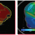
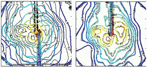 Figure 19.4. Dose distributions for simulated respiratory motion with (right) and without (left) the use of Synchrony tracking. The underlying black curves are isodose lines generated by the treatment planning system. The colored curves are the same isodose lines measured after treatment delivery with respiratory motion. The isodose lines are displayed in 0.5-Gy increments, with the highest isodose line being 4.0 Gy. The scale is defined by the length of a side of the square dosimetry film, which is 6.3 cm. The amplitude of motion was 20 mm, the motion pattern was a sin2(ωt) waveform, and the period was 7 seconds. These results show isodose line distance to agreement to be generally better than 1 mm, with a maximum displacement of 2 mm. (Images courtesy of Drs. J.P.A. Marijnissen and Y. Seppenwoolde, Erasmus Medical Center-Daniel den Hoed Center, Rotterdam, the Netherlands.) |
SUMMARY
This section described the CyberKnife System design and explained how it addresses the two major technical requirements associated with radiosurgery:
High conformality and steep dose gradients in all directions are achieved through the combination of a robotic manipulator, which enables routine use of a large number of nonisocentric, noncoplanar beams that are individually targeted at unique points within the patient without the need to reposition the patient for each beam; variable collimation, which enables multiple field sizes to be combined within each treatment such that a complex dose distribution can be constructed from a set of independently targeted and sized pencil beams; and powerful plan optimization algorithms, which select optimal beam weights, beam directions, and field sizes.
High accuracy of treatment beam alignment and delivery is achieved through the combination of an x-ray image guidance system, which enables frameless alignment based on the target anatomy or an internal surrogate for all body sites; a robotic manipulator, which enables each beam to be aligned to the target volume rather than the less accurate approach of moving the patient to align the target volume to each beam; and continual image guidance and alignment corrections throughout every treatment fraction, such that there is no dependence on an absence of intrafraction motion.
BRAINLAB IMAGE-GUIDED RADIATION THERAPY SYSTEMS
EXACTRAC X-RAY 6D
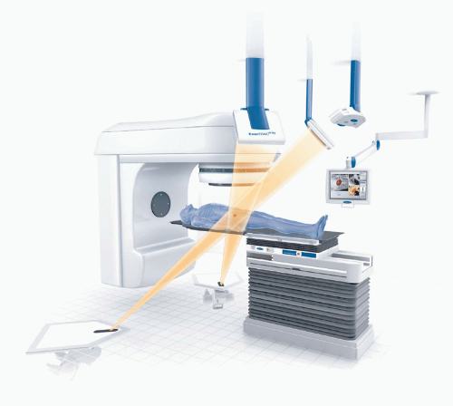
BrainLAB’s (Heimstetten, Germany) image-guided positioning system, ExacTrac X-Ray 6D, is fully integrated into the Novalis radiosurgery unit but is also available as an add-on solution for Elekta, Siemens, and Varian standard linacs. The system combines infrared (IR) tracking of reflective markers with stereoscopic x-ray imaging. For image-guided radiation therapy (IGRT) imaging, two x-ray tubes are embedded in the treatment room floor, and two amorphous silicon detectors are mounted to the ceiling (Fig. 19.5). The x-ray system produces beams ranging from 40 to 150 kV and projects a field size of approximately 20 × 20 cm on the detectors. The beam axes of both x-ray tubes cross the treatment beam axis (linac isocenter) so that the images are taken isocentrically. ExacTrac Robotics (an automated tilt module with a carbon table top controlled by ExacTrac X-Ray software) allows for correction of pitch and roll rotations of up to 3 to 4 degrees, whereas isocentric couch rotation is used for automatic yaw compensation. Two IR cameras are installed in the treatment room for patient prepositioning and real-time monitoring.
System Performance
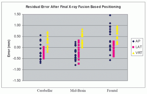
With the increasing use of hypofractionation and intensity-modulated techniques in clinical routine, quick and accurate image-guided patient positioning is necessary. A study at
Harvard Medical School showed that the residual error of the ExacTrac positioning system after fusion was <1.5 mm, with a mean total system error of 0.7 mm (Fig. 19.6).54 A recent report from Free University of Brussels found the average time for a prostate cancer patient setup with 6D correction and verification to be 3 minutes 11 seconds using ExacTrac X-Ray 6D on a Novalis linac.55 With this quick patient setup, treatment time from the first x-ray until beam-off was found to be a mean of 9.0 minutes for five to seven coplanar intensity-modulated radiation therapy (IMRT) beams.56
Harvard Medical School showed that the residual error of the ExacTrac positioning system after fusion was <1.5 mm, with a mean total system error of 0.7 mm (Fig. 19.6).54 A recent report from Free University of Brussels found the average time for a prostate cancer patient setup with 6D correction and verification to be 3 minutes 11 seconds using ExacTrac X-Ray 6D on a Novalis linac.55 With this quick patient setup, treatment time from the first x-ray until beam-off was found to be a mean of 9.0 minutes for five to seven coplanar intensity-modulated radiation therapy (IMRT) beams.56
In addition to accuracy and speed, dose added on top of the prescribed dose may be of concern for some patients. The radiation dose per x-ray image using the ExacTrac system is 0.5 mSv. Therefore, a protocol including two images for setup correction and two images for patient position verification would add 2.0 mSv to the radiation dose prescribed.55 This dose is low in comparison to the acquisition of a single cone beam CT (CBCT) data set, which adds an additional dose of 14 mSv.57
Image-guided Radiation Therapy Clinical Workflow
Prior to treatment, the patient is roughly aligned to the isocenter with the help of skin marks and lasers. For target localization, two orthogonal x-ray images (one from each tube) are taken from the planned isocenter region of a prepositioned patient. Because the ExacTrac X-Ray 6D is a room-based system, imaging does not require gantry rotation or extension and retraction of flat panel detectors. The two images are then compared to the DRRs from the planning CT using automated image fusion to calculate correctional shifts and rotation in six dimensions. IGRT verification is either performed on the basis of automatic image fusion of bony anatomy or, in the case of prostate or lung tumors, on the automatic detection of implanted markers.
Stay updated, free articles. Join our Telegram channel

Full access? Get Clinical Tree


