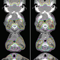
Fig. 2.1
Example of an IMRT case in which the tongue-and-groove effect resulted in a line of reduced dose through the target. Black isodose lines show the calculated dose distribution; colored isodose lines, the results of film-based IMRT quality assurance
The leaf end shape is also important. It can either be straight, in which case the collimator moves along the circumference of a circle, with the ends of the leaves always remaining along the divergent x-ray beam, or rounded, for designs in which the MCL moves perpendicular to the beam central axis. When MLCs have rounded ends, an offset of 0.4–1.1 mm is present between the edge of the radiation field and the nominal location of the MLC leaf, depending on leaf design, beam energy, and distance from central axis [40]. The effect of this offset must be included in the treatment planning system dose calculations.
The accuracy and precision of MLC positioning are also important. In conventional conformal RT, MLCs are used to define the aperture of the treatment beam, thereby conforming it to the treatment target. When used in this way, an uncertainty in the leaf position of 1–2 mm may be acceptable, because an uncertainty of this size (typically small compared with the total aperture size) has only minimal effects on the radiation output. However, in IMRT the situation is very different. First, the segments can be quite narrow (<1 cm), and uncertainties of only a few tenths of a millimeter can cause errors of several percentage points in delivered dose. Further, the cumulative dose distribution in IMRT comprises contributions from many segments. The beam edges move to many different locations during the treatment (i.e., not just at the edge of the target as is the case in conformal treatments), so it is essential that their positional accuracy is maintained to better than a millimeter. Without this level of accuracy, the contributions of the different segments may not sum correctly [40].
2.4 Volume-Modulated Arc Therapy
VMAT is a form of IMRT in which the treatment is delivered in one or more dynamically modulated arcs [5, 16, 93, 94, 104]. As the gantry rotates, the MLCs move, giving a different aperture shape for each angle of the gantry. The rate of rotation of the gantry and the LINAC dose rate can both be modulated during treatment to give the required delivered dose for each gantry angle. The quality of the planned dose distributions that can be achieved is equivalent to those that can be achieved with other forms of IMRT. The plan quality depends on achievable modulation, which, in turn, depends on the gantry speed, number of arcs, or both. The main advantage of VMAT is that the entire treatment can be completed quickly. For example, a typical treatment of two complete 360° arcs, with different couch rotations for each arc, takes less than 2.5 min. This advantage is significant, especially for a busy clinic, and thus we expect that VMAT will become the IMRT delivery technique of choice for most treatments.
2.4.1 Leaf Sequencing
As noted above, some optimization algorithms do not consider the physical characteristics or limitations of the delivery system when calculating the optimal intensity distribution. This optimal intensity is then used to create the MLC leaf positions (leaf positions as a function of time/monitor units [MUs]) that will deliver a fluence that is as close as possible to the optimized distribution.
In step-and-shoot multifield IMRT, modulated delivery is achieved with multiple static MLC segments, with each segment having its own aperture shape and weight (MU). The leaf-sequencing algorithm first coverts the optimized intensity distribution to discrete levels, which are then converted into separate MLC segments (Fig. 2.2). The ideal algorithm will create an MLC sequence for which the summation of all the segments gives a delivered fluence that is close to the optimized fluence, uses the minimum number of segments, and may also minimize the MLC motion between segments. In general, the agreement between the optimized and delivered intensity distribution increases as the number of intensity levels is increased. This process has been shown to increase the target coverage, but it also results in an increase in the number of MLC segments (MLC shapes). Because the beam is turned off as the MLCs move between segments, this can significantly affect the treatment delivery time. The advantage of step-and-shoot delivery is that factors such as MLC speed and dose rate are less important, so the IMRT delivery is possible with a less advanced treatment machine. Also, importantly, step-and-shoot IMRT typically requires less MUs than dynamic IMRT.

Fig. 2.2
(a) Leaf trajectory as a function of dose index for a step-and-shoot IMRT delivery. (b) is the resulting fluence map (From Xia and Verhey [133])
In sliding-window IMRT delivery, the MLCs move across the target volume while the radiation is on [8, 13, 40, 113]. The size of the gap between opposing MLCs and the speed of the MLCs are constantly changing. The dose rate may also be adjusted. Conceptually, the amount of radiation received by a point within the target is proportional to the number of MUs delivered while the system is in the open gap. When the two opposing leaves are far apart, the delivered dose is high; when they are closer together, the delivered dose is reduced (see Fig. 2.3). To account for unexpected variations in dose rate, the position of the MLCs is indexed to the delivered MUs rather than to time. Advantages of sliding-window IMRT include faster delivery than step-and-shoot IMRT, reduced numbers of MUs, and potentially reduced wear and tear on the MLC mechanism (because motion is mono-directional).

Fig. 2.3
(a) Leaf trajectories as a function of dose index for dynamic multileaf collimator (MLC) delivery. (b) is the resulting intensity fluence (From Xia and Verhey [133])
The delivered and ideal fluence can differ for several reasons, including overly complex ideal fluence distributions [80] and practical limitations related to the leaf design (transmission, non-divergent leaf end design, leaf scatter) [99]. Although these limitations reflect the choice of the planning and delivery system, treatment planners can take steps to minimize them. For example, planners should take care not to push the IMRT optimization excessively, as can happen when extreme values of the weights are used for the DV constraints. Some planning systems also allow the planner to control how smooth the ideal fluence will be. One way to monitor fluence complexity is to ensure that the MU per beam is not unusually high. Commonly, the agreement between ideal and deliverable MU decreases as the MU increases. Also, the complex MLC patterns that high-MU fields require can be more difficult for the MLC controller to deliver, resulting in unwanted delays at the time of treatment.
2.4.2 Jaws-Only IMRT
As described above, with MLC-based IMRT, MLCs are used to create many irregular shapes that are superimposed to create a complex fluence pattern. Complex fluences can also be created from many rectangular segments created by the LINAC jaws alone [38, 41]. The main advantage of jaws-only IMRT is the lack of additional complexity and expense of an MLC, which could allow IMRT to be achieved at lower cost. One possible application of this approach could be a low-cost LINAC for low- and middle-income countries, where affordable, reliable RT equipment is desperately needed [47–49]. In modern radiation therapy centers, however, IMRT is dominated by MLC-based delivery.
2.4.3 Image-Guided IMRT
IMRT alone can achieve impressive dose distributions, reducing toxicity to normal tissues. However, the high conformality that can be achieved with IMRT increases the need for image guidance (i.e., IGRT). Moreover, realizing these planned dose distributions over a treatment course lasting days or weeks requires highly accurate patient setup, particularly when taking advantage of tight dose distributions could lead to use of margins as small as 3–5 mm [30]. Many approaches are used for IGRT, including orthogonal (or stereotactic) kilovoltage or megavoltage x-ray imaging and CT imaging (cone beam or CT on rails), and MRI-guided treatments are only a few years away [57, 83, 102, 109]. Specifics of IGRT for IMRT are discussed elsewhere in this book.
2.5 Intrafraction Motion and IMRT
Use of IMRT to treat tumors in regions of the body that experience involuntary intrafraction motion (e.g., tumors in the lung or liver that move with respiration or tumors in the lower abdomen that move with the passing of bowel gas or other involuntary bodily functions) has been controversial for two reasons, namely, the potential for geometric miss and interplay effects between the motion of the tumor and the motion of the machine (gantry, collimator, and MLC) used to create the modulation pattern [10, 107, 136]. Both of these concerns can be managed by appropriate imaging and plan design.
The issue of geometric miss should be addressed by design of appropriate margins (in the same way that all geometric uncertainties are addressed) and the IGRT process (understanding the relationship between the imaging surrogate and the actual target and realizing that this relationship can be influenced by the motion management technique that is chosen). Motion can also be minimized by gating, abdominal compression, or other approaches [56]. Any residual motion should be carefully evaluated and included in the treatment margins.
The issue of the interplay effect has been extensively studied, and although extremely large dose deviations are theoretically possible, such deviations are generally not found in the MLC sequences of real clinical cases. Even when the interplay effect does cause dose deviations from day to day, these deviations average out after a few fractions [26]. Notably, however, treatment planners could potentially create an extremely complicated, overmodulated plan for which the interplay effect can become important. In situations where possible interplay effects are a concern, the dosimetric errors caused by the interplay effect can be reduced by reducing the dose rate [25]. This works because the longer treatment times result in more opportunities for the effects to average out. For the same reason, the interplay effect is not expected to be a significant clinical issue with stereotactic ablative RT (where the doses are high and treatment times are long). Another planning technique shown to reduce the impact of interplay effect for VMAT plans is to use several arcs instead of a single arc [26]. To minimize any interplay effects when moving targets are treated with IMRT (or VMAT), treatment planners should take care to not overmodulate the treatment plan and to use multiple arcs. If these approaches are not possible, a reduced dose rate can be considered.
2.6 Quality Assurance Specific to IMRT
2.6.1 Commissioning and Routine Machine Quality Assurance
Rigorous commissioning of the processes for IMRT planning and delivery is absolutely essential. Nevertheless, the Radiological Physics Center, an imaging and radiation core QA facility based at MD Anderson Cancer Center, has reported that as many as 28 % of institutions failed to meet even the loose criteria of ±7 % dose accuracy or 4 mm distance to agreement in a high gradient when subjecting a head and neck phantom to IMRT [51]. This is a rather frightening statistic, given that these institutions were obtaining credentials for implementing clinical trials involving IMRT (and presumably thought their planning and delivery process was adequate to treat patients). Although some of the failures resulted from incorrect phantom setup, other reasons include incorrect output factors in the treatment planning system, incorrect CT-to-density conversion, and inadequacies in beam modeling at the leaf ends. The commissioning process involves careful measurement of any physical parameters that the treatment planning system may need (e.g., MLC transmission), evaluation of the mechanical and radiation characteristics of the delivery system (e.g., MLC leaf positioning accuracy) [58], and end-to-end tests. Many of the tolerances (for commissioning or routine QA of IMRT equipment) are different than for non-IMRT machines. For example, step-and-shoot IMRT can involve segments with few MUs; the dose per MU, as well as flatness and symmetry of the beam, should be checked throughout the range of MUs used for IMRT [40, 58].
In addition to measuring individual characteristics of different parts of the delivery process, end-to-end tests are important as well. The American Association for Physicists in Medicine created a series of tests for IMRT commissioning that are designed to represent common clinical treatments. These tests include the measurement of point dose and also dose planes assessed by using the gamma criterion of 3 %/3 mm, the most prevalent standard for acceptance testing and QA [87]. Nine centers (all of which passed the Radiological Physics Center’s phantom irradiation) planned, delivered, measured, and analyzed these tests, and the findings were used to create confidence levels for use as reference by other institutions attempting the same tests. Notably, however, despite the common acceptance of 3 %/3 mm as a standard [3], other criteria can be used; moreover, the 3 %/3 mm standard may not be appropriately “tight” for commissioning or for patient-specific QA [22]. Some have proposed a DVH-based metric as the final goal [15].
2.6.2 Patient-Specific Quality Assurance
Each plan in IMRT can be highly complex, and completing patient-specific QA before a patient’s treatment is begun is common practice [3, 39, 40, 46, 103, 111]. This process verifies the ability of the treatment planning system to calculate the dose accurately for this patient’s plan (which can be done with a secondary dose calculation software package, as used in conventional RT) and the ability of the delivery system to accurately deliver the dose. Typically, the QA process involves comparing a dose plane delivered to a regular phantom with the dose calculated by the treatment planning system for the same geometry [87]. However, correlation can be lacking between conventional IMRT QA passing rates and actual dose errors in anatomic regions of interest [88]. For example, plans can pass planar IMRT QA but still have relatively large dose errors to some of the patient’s anatomy. For example, Kruse and colleagues concluded that gamma analysis on a per-plane basis for a set of highly modulated head and neck plans was insensitive for detecting calculational errors [60]. In a separate study, McKenzie and others found that some devices were relatively insensitive for detecting failing plans [75]. That said, these QA approaches should not be discounted, as they do ensure that no large errors in dose calculation are present. Products are now available that include a calculation of the dose to the patient’s anatomy (rather than just to a dose plane in a phantom), although these products are still relatively new [22, 86, 91, 126]. Details on how to commission IMRT QA equipment and processes, equipment choices, and QA criteria are available elsewhere [39, 40, 78].
2.6.3 Process Quality Assurance
As indicated previously, the delivered dose distribution is less likely to match the planned distribution if the plan is excessively complex. Modeling MLCs tends to be more important for complex plans (e.g., the tongue-and-groove effect), and the interplay effect is also more pronounced for complex plans, underscoring the desirability of avoiding these complex plans. Complexity can be quantified in a variety of ways, including average distance between opposing MLCs, but the easiest is probably to quantify the number of MUs for the total plan. Plan MUs depend on a variety of factors, including treatment planning system, IMRT approach (step-and-shoot vs. sliding window), and expectations of the clinicians (tighter constraints or many iterations during the planning process will invariably result in plans with higher MUs). In the example shown in Fig. 2.4, a single, relatively inexperienced treatment planner was responsible for all plans that involved more than 2,000 MUs. Interestingly, this planner’s plans tended to have more broken-up isodose lines as well as higher MUs, indicating that optimization engine was being overworked, which probably led to constraints being weighted too strongly. About a year after these data were obtained, the expected plan MUs had dropped significantly.

Fig. 2.4
Frequency distribution of total plan monitor units (MUs) in sliding-window IMRT for head and neck treatment at a single institution (These data were obtained in 2005, relatively early in the institution’s experience with IMRT; in subsequent years, the total numbers of MUs were lower)
2.7 Facility Design for IMRT
The number of monitor units required for IMRT plans is much higher than that needed for conformal RT plans (with the exception of VMAT), leading to a significant increase in radiation “leakage.” This leakage should be accounted for in shielding calculations by using the so-called IMRT factor, the ratio of average MU per unit prescribed absorbed dose needed for IMRT and the MU per unit prescribed dose for conventional treatments [84, 85]. The IMRT factor is a function of treatment site (being lower for simple plans like breast, higher for more complex plans like head and neck), delivery mode (higher for sliding window than for step-and-shoot IMRT), and treatment planning system (e.g., efficiency of the MLC sequencer). Given the wide range in published values (from 2 to 10 or more), the shielding designer should ensure the use of appropriate values, erring on the conservative side. An additional consideration when designing a new treatment room is that IMRT tends to require less high-energy beams [95, 112, 119], in which case the high-energy workload may be reduced.
Tomotherapy, which is a special case of IMRT, has a narrow fan beam that is only a few centimeters long; thus, the primary barrier can be much narrower than that required by a conventional treatment unit. The IMRT factor for these units is relatively high, meaning that the secondary shielding barrier may have to be thicker than for conventional treatments [85]. The secondary shielding barrier requirements for scattered radiation are the same in tomotherapy and IMRT as for conventional treatments.
2.8 Advantages and Challenges of IMRT
The ability of IMRT to shape the dose around the target, thereby minimizing dose to adjacent normal structures, is significant, especially for individual patients. However, IMRT also has some limitations. In many cases, these limitations can be mitigated by careful clinical implementation (guided by awareness of the limitations) and future technology developments. Some of the advantages and disadvantages of IMRT are noted briefly below.
2.8.1 Higher Conformality/Margin Reduction
The high degree of conformality possible with IMRT can significantly improve normal tissue toxicity [4, 100, 106, 115, 129, 137], as discussed elsewhere throughout this volume. Combining this high degree of conformality with IGRT offers the potential for further reducing toxicity while maintaining local-regional control [64]. One group successfully reduced PTV margins for patients with head and neck cancer from 5 to 3 mm, reducing the incidence of gastrostomy tube dependence and esophageal stricture but without affecting local-regional control [19]. Image-guided IMRT may also offer the possibility of dose escalation, which can improve control of some tumors [117]. Of course, the risk is that inappropriate reduction in treatment margins will result in geographic miss of the tumor. Little clinical data are available on this issue, but careful understanding of the uncertainties accounted for in the PTV margin is necessary before any reduction is implemented. Even IGRT can still involve significant uncertainties that must be considered, particularly in target delineation [18, 77, 97, 130] and the actual extent of microscopic disease [123], but also in interfraction and intrafraction motion/deformation [121, 122].
2.8.2 Treatment Errors
Error rates in RT have been reported to be less than 1 % per fraction [42, 43, 70]. Moreover, the error rate is often reduced as new technology is introduced. For example, one group showed that the introduction of MLCs reduced error rates relative to “low-technology” machines without MLCs [72]. Error rates with IMRT have also been reported to be lower than those with three-dimensional/conventional RT [71]. One of the main reasons for the lower error rates is that IMRT usually does not involve the use of accessories (e.g., blocks, electron cones), the incorrect use of which is one of the main source of errors in conventional RT. Other reasons are that patients who require urgent treatment (with correspondingly rushed planning) tend to be treated with techniques other than IMRT. Presumably, the extensive patient-specific QA that is carried out for IMRT patients is also important in reducing error rates.
Even though the introduction of new technology tends to reduce error rates, the types of errors change when new technology is introduced. In one analysis, the most common errors with IMRT were found to be related to incorrect data entry (to the record-and-verify system) compared with conventional treatments, for which accessory and setup errors were more common [71]. As integration of the planning system, record-and-verify system, and treatment delivery system improves, the probability of such errors should be progressively reduced. Several IMRT treatment errors have had devastating consequences [50], including a well-publicized case in which a series of computer errors resulted in a patient being treated with MLCs parked in the open position instead of moving across the field to modulate the x-ray intensity. In addition to technology failures, treatment errors can also occur because of the different data needed to commission treatment planning systems for IMRT. For example, very small fields are possible in IMRT. If these are measured incorrectly (e.g., by using too large a detector), this can result in incorrect treatments [50]. Similarly, the radiation characteristics of MLCs (e.g., transmission) make a larger contribution to IMRT treatments than for conventional treatments, so incorrect entry of these parameters into the treatment planning system can result in incorrect dose calculations. Thus, as is true with any new technology, the clinical implementation of IMRT must be approached cautiously, with an understanding of the risks, full consideration of the workflow/processes, and appropriate staffing levels, training, tools, and techniques. Further guidance on safety considerations in IMRT is available elsewhere [82].
2.8.3 Unanticipated Clinical Consequences
IMRT dose distributions can be quite complex and are unusual in comparison with dose distributions from the pre-IMRT era. For example, depending on the technique or treatment site, high doses may be close to normal tissues, and large volumes of normal tissue may be exposed to low doses. Some of the dose-response data used clinically may have been based on patients who were not treated with IMRT, and care is needed when using such data to evaluate dose distributions from IMRT plans to avoid unanticipated clinical consequences. An example of such consequences was described by Allen and colleagues, who found that IMRT for mesothelioma led to an unexpectedly high rate of fatal pneumonitis [2]. This case highlighted the need for extreme care when applying DVH constraints to new clinical treatment techniques [2, 59].
2.8.4 Out-of-Field Dose and Secondary Malignancies
Patients treated with RT may be at increased risk of developing secondary malignancies caused by radiation outside of the treatment volume (i.e., out-of-field dose) [7, 14, 61]. For example, before the introduction of IMRT, Brenner and colleagues found the absolute risk of secondary malignancies caused by out-of-field dose to be 1.4 % among patients surviving more than 10 years after treatment [14]. Sources of out-of-field dose include photon leakage (proportional to MUs), radiation scattered from the collimators (also related to MUs), radiation scattered within the patient (proportional to target dose) [114], and neutrons, which are produced mostly through high-energy photons interacting with high-Z materials (e.g., tungsten or lead) [62]. Contributions of these factors depend on photon energy as well as distance from the target, with the former MU-dependent sources being most importantly distant from the field edge. Although the higher MUs required for IMRT mean that the risk of secondary malignancy is unavoidably higher, this increase can be minimized to some extent by the choice of IMRT approach (e.g., dynamic IMRT delivery vs. step and shoot) and energy (see Kry et al. [61]).
2.8.5 Concerns About Interplay Effects
The dose delivered to a tumor can vary from day to day when IMRT (whether step and shoot, dynamic, or VMAT) is used to treat moving tumors [9, 12, 29, 37, 107]. This variation results from the interplay between motion of the tumor and motion (or changing aperture shape/position) of the delivery system. As previously discussed, this effect can generally be minimized by careful planning that avoids overly complex plans. That is, for dynamic IMRT, small MLC separation and fast MLC motion should be avoided; for step-and-shoot IMRT, small segments with small MUs should be avoided; and for VMAT, more than one arc should be used. Interplay effects in complex treatment plans can be avoided by reducing the dose rate (and thus reducing the MLC speed and allowing more averaging over the respiratory cycle). In all but the most complex situations, dose deviations average out after several (<5) fractions [26]. Use of IMRT to treat moving targets is discussed in greater detail elsewhere in this volume.
2.8.6 Changes in Workflow
Another potential disadvantage of IMRT is the increased effort needed to create and check each treatment plan. Many factors contribute to the overall time needed to prepare an IMRT plan, including contouring of many more structures than for 3D conformal RT, plan optimization, and phantom planning (for patient-specific QA); the main factor is probably the time spent waiting for the treating physicians to provide target volumes [32]. The need for patient-specific IMRT QA before the first treatment can also add significantly to the effort in preparing a plan for treatment [79, 96]. Selection of the treatment planning system and other tools is important here; for example, some planning systems have better tools for manipulating structures (e.g., cleanup, processing, Boolean operations to combine anatomic structures or to exclude overlapping regions) than others [32]. Similarly, dose calculation times can vary widely between planning systems. Radiation oncology researchers and equipment manufacturers are investing considerable effort in developing segmentation, treatment planning, and general work management tools to improve the workflow of IMRT plan preparation, including reducing variations between users [36, 92, 134, 135], so these potential hurdles to the smooth integration of IMRT are being addressed.
The introduction of IMRT can also make some positive contributions to workflow. For example, forward planning can be extremely difficult. In some cases, only the best treatment planners can create conformal treatment plans that meet the clinical goals of target coverage, minimal dose hotspots, and acceptable normal tissue doses. The process of inverse planning, in which the plan is automatically created based on user-defined dose objectives, can significantly simplify this process. This reduction in planning time with IMRT has been noted by several groups [1, 73]. Also, because IMRT typically uses treatment beams from more directions than most conformal plans, the choice of beam angle is less important. Together, this means that at least in some cases, IMRT treatment planning is actually easier than planning for conventional treatments. Ongoing developments in multi-criteria optimization and automated plan optimization are further leading to greater planning efficiency and improved consistency and quality of IMRT plans. Multi-criteria optimization techniques allow users to navigate a space of multiple plans favoring individual anatomic structures to trade off competing clinical objectives; automated plan optimization automatically adjusts specified objectives and beam configuration to achieve an improved dose distribution.
2.8.7 Treatment Time
When IMRT was first introduced, the “beam-on” treatment time was significantly longer for IMRT than for treatment that involved conventional static fields. However, this time increase varies widely depending on the delivery technique [6]. Although this disadvantage still exists for some forms of IMRT, the relatively recent clinical introduction of VMAT, in which treatment is delivered with 1 or more arcs around the patient, means that IMRT treatments are much faster than the original forms [21, 31, 93, 98]. In fact, in cases in which conventional treatment would have included electron and photon fields, VMAT treatments are faster than conventional treatments.
Related posts:
 Sequelae of Therapy of Head and Neck Cancer: Their Prevention and Therapy
 Thoracic Esophageal Cancer
 Treatment Planning of IMRT for Head and Neck Malignancies
 Clinical Application of IMRT for Cervical Esophageal Cancer
 Postoperative Intensity-Modulated Radiation Therapy for Head and Neck Cancers: A Case-Based Review
Stay updated, free articles. Join our Telegram channel

Full access? Get Clinical Tree


