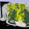
Fig. 46.1
(a) Screenshot of the neuroArm human-machine interface showing the integration of 3D magnetic resonance images with surgical planning (blue cone) and robotic tools (blue and off-white) to target patient pathology. (b) Timeline showing the chronological introduction of technologies into clinical neurosurgery. Over the past 20 years, robotic systems have been developed to couple the executive decision-making capacity of the surgeon with the accuracy of imaging technology and the precision of advanced robotics
Neurosurgical robotics (Table 46.1) began with the introduction of an industrial robot, Programmable Universal Machine for Assembly (PUMA), into the operating theatre in 1985 [21]. In 1987, Benabid et al. coupled the PUMA 200 robot to a Brown-Roberts-Wells (BRW) head frame for frame-based stereotaxy [22]. The robotic arm had six degrees of freedom (DOF), and each joint was equipped with spring-applied, solenoid-release brakes that would immediately stop motion should any system defect arise. Using CT imaging for navigation, the system was able to orient a cannula for needle insertion. The robot was modified to hold a retractor for the resection of multiple pediatric thalamic astrocytomas in 1991 [23]. These developments provided proof of concept of robotic neurosurgery, allowing multidisciplinary research teams to begin development of robotic systems designed for specific neurosurgical applications.
Table 46.1
The evolution of neurosurgical robotics
Year | Project name | DOF | # EE | Navigation | Imaging | Purpose | Documented use | Accomplishments | Limitations |
|---|---|---|---|---|---|---|---|---|---|
1988 | 6 | 1 | BRW frame | CT | Retractor | Glioma surgery | First neurosurgical robot Demonstration of safety | No FDA approval safety concerns with industrial robot in OR | |
1994 | 5 | 1 | BRW frame | CT | Image guided surgery | Stereotactic biopsy Stereotactic implantation | Mounted inside CT machine | Only five DOF Requires dedicated CT scanner Obstructive within CT gantry | |
1997 | CyberKnife [43] | 6 | 1 | Frameless | X-Ray | Radiosurgery | Neurosurgical radiation | Focused radiosurgery FDA approved | Expensive |
1999 | 6 | 1 | N/A | N/A | Microsurgery | Rat carotid endarterectomy | Microsurgical ability | No haptic feedback Increased length of procedure | |
1999 | Steady Hand [26] | 6 | 1 | N/A | N/A | Microsurgery | Tremor filter and motion stabilizer | Increased surgical precision Haptic feedback | No image guidance No clinical application |
2001 | 5 | 1 | Frameless | MRI | Navigation and tool placement | Position needle holder | Non-magnetic actuators | Pointing device only | |
2002 | 6 | 1 | Frameless | MRI | Endoscopy | Neuroendoscopy Endoscopic ventriculostomy Transphenoidal skull base surgery | Endoscopic application | Narrow working envelop Single arm No haptic feedback | |
2003 | 5 | 1 | Frame based or Frameless | CT | Stereotaxy and lesion localization | Stereotaxy Functional neurosurgery Drilling at the skull base | Commercially-available First FDA-approved neurosurg robot Diverse clinical application | No microsurgical ability No tool actuation | |
2003 | 3 | 3 | Frameless | N/A | Microsurgery | Tumor resection | Partial resection of meningioma Telesurgery on rat from 40 km away | Limited to three DOF for each arm Low payload | |
2005 | 6 | 1 | N/A | Fluoroscopy | Stereotaxy | Percutaneous facet block | Accuracy comparable to manual technique | Movement occurs in one DOF at a time Requires fluoroscopy suite | |
2006 | Pathfinder [31] | 6 | 1 | Frameless | CT | Stereptaxy | Epilepsy surgery | Highly accurate navigation | CT required for feducial placement Surgical ergonomics |
2006 | 6 | 1 | Frame based | CT | Spinal instrumentation | Guide for tool positioning Guide for screw placement | FDA approval for spinal surgery | Limited range of application | |
2009 | NISS [32] | 5 | 1 | CT | CT | CT-guided navigation | Image-guided implantation | In vivo and in vitro surgical implantation | Ionizing radiation |
2009 | 7 | 2 | Frameless | MRI | Pre-surgical planning Microsurgery and stereotaxy | Various intracranial pathology Intracranial tumor resection Drainage of cerebral abcess | Microsurgery and stereotaxy MRI-compatible robot and tools Haptic feedback | Expensive |
In 1994, Frankenhauser et al. introduced the Minerva robot [24]. The system was coupled to the same BRW head frame used by Benabid and mounted inside a CT scanner for image-guided biopsy and implantation. Unfortunately, the requirement of a dedicated CT scanner limited applicability of Minerva to the neurosurgical community at large. Two systems, the Robot-Assisted Microsurgical System (RAMS) and Steady-Hand Robotic System, were developed in 1999 to enhance microsurgery [25, 26]. While these projects were shown to improve microsurgical precision and provided haptic feedback, respectively, they have not yet been clinically applied.
By the year 2000, advances in computer technology, the ubiquity of neurological imaging, and increasing adaptation of robotic technology across the manufacturing and aerospace industries provided the potential for development of an image-guided neurosurgical robotic system. The Harvard MRI robot was developed and integrated with intraoperative MR imaging (iMRI) [27]. The robot manipulator was MR compatible and used for intraoperative tool orientation. NeuRobot emerged as a microsurgical robot in 2003 [28]. It was tele-capable and tested in an experimental model with the surgeon located 40 km away from the surgical site.
In addition to developments in microneurosurgery, robotic systems were designed for endoscopic and stereotactic application. The Evolution I robot was developed for endoscopic applications and used in 2002 for the transsphenoidal removal of pituitary adenoma [29]. The CT-based NeuroMate system became the first neurosurgical robot to receive FDA approval for clinical use [30]. The Pathfinder system followed in 2006, with highly accurate CT-guided stereotactic application [31]. Finally, the NISS collaboration was published in 2009 with direct application in CT-guided implantation procedures [32].
Two important robotic systems have been developed for spinal surgery. In 2005, the Georgetown robot was used for fluoroscopy-guided percutaneous facet blocks in cadaveric studies and clinical patients [33]. Accuracy was deemed comparable to manual technique, but movement was only available in one DOF at a time. The SpineAssist robot has been used for tool positioning and pedicle screw placement [34]. It received FDA approval and is commercially available to this day.
neuroArm
Advances in technology provided the opportunity to develop a robotic system capable of both microsurgery and stereotaxy [35]. Furthermore, due to the increasing acceptance of intraoperative MR imaging, it was also desirable to construct a system that could operate within this imaging environment [36]. While this presented significant challenges regarding material selection, technological equipment, and surgical processes, it would resolve the problem of disrupting surgical rhythm for intraoperative image acquisition. In 2002, investigators at the University of Calgary (Calgary, Alberta, Canada), in collaboration with MacDonald, Dettwiler and Associates, began the development of such a robot.
neuroArm: Design and Manufacture
The initial requirements document for neuroArm included the ability to perform both microsurgery and stereotaxy within the bore of a 1.5 T magnet. At the time of preliminary design review, it became evident that stereoscopic vision, a necessary requirement for microsurgery, could not practically be captured within the magnet bore. Furthermore, due to requirements of payload (750 g) and speed (200 mm/s), as well as the size of the existing position encoders, the manipulators needed to be relatively large. Both could not be placed within the 70-cm working aperture of the intraoperative 1.5 T magnet. For these reasons, scope was changed such that image-guided microsurgery would be performed outside of the bore of the magnet and stereotaxy, using a single arm, within the bore of the magnet.
Manipulators
neuroArm consists of two arms called manipulators, each has a total of seven degrees of freedom: six spatial and one degree of tool actuation [37]. Each manipulator was designed to reflect the limbs and joints of a human surgeon: shoulder joint to allow for rotation in both the horizontal and vertical plane, elbow joint to allow for flexion/extension of the arm, and a wrist joint to allow adjustment of rotation and pitch. Tool actuation is accomplished through motion of one tool holder relative to the other. The arms are mounted on a mobile base, which allows height adjustment to accommodate the position of the operating table.
To achieve MR safety, the manipulators were manufactured from titanium, polyetheretherketone (PEEK), and polyoxymethylene (Delrin, Dupont, Wilmington, DE). Motion of the arms is accomplished using ultrasonic piezoelectric actuators (Nanomotion, Yokneam, Israel) that have a 20,000-h lifetime, 1-nm resolution, and inherent braking characteristics if power is lost [36, 37]. Absolute 16-bit sine/cosine encoders provided 0.01° accuracy at each joint and retained positional information when powered off for imaging. Haptic feedback was provided in three translational degrees of freedom from six-axis force/torque sensors (ATI Industrial Automation, Apex, NC) that were specifically manufactured for neuroArm. The end effectors were designed to hold a variety of tools using a standardized interface that allows for tool roll and tool actuation (Fig. 46.2).
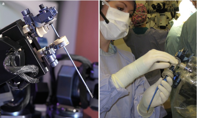
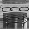
Fig. 46.2
(a) The neuroArm end effector uses two standardized connectors (blue) to hold a surgical tool. The upper connection includes a gear to control tool roll, while the lower connection moves upward and downward to allow for tool actuation. (b) During surgery, the neuroArm manipulators are draped for sterility, while the two standardized tool connectors penetrate the drape. The scrub nurse is able to exchange all the neuroArm tools with the standardized tool connectors
Mobile Base
The manipulators are moved in and out of the operating room on a height-adjustable mobile base. A digitizing arm, mounted on the mobile base, allows registration of the manipulators to the radio frequency (RF) coil. The information, transferred to the computerized human-machine interface, allows 3D MR image display with tool overlay. The field camera, mounted on the mobile base, provides overall visual feed of the surgical field. For stereotactic procedures, the mobile base is used to transport the manipulators to a platform inserted into the MR magnet (Fig. 46.3).
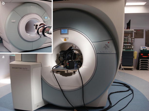
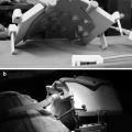
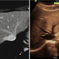
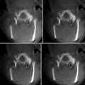
Fig. 46.3
(a) During stereotaxy, one neuroArm manipulator is placed on a specialized board within the iMRI magnet bore, opposite to the patient. (b) The iMRI machine moves to the operating table, so the patient and neuroArm end effector meet at the magnet isocenter. Stereotaxy near the magnet isocenter allows for simplified registration and optimized image quality throughout the procedure
Main System Controller
The main system controller consists of four main software applications, each operating on an individual computer: (1) The command and status display provides the main graphical control interface for the neuroArm end effectors. (2) The MRI display provides 2D and 3D volumetric images of patient pathology with tool overlay. (3) The hand controller interfaces to the left and right human-machine interface hand controllers process kinematic motion at the human-machine interface. (4) The controller interfaces to the manipulator arms and other hardware.
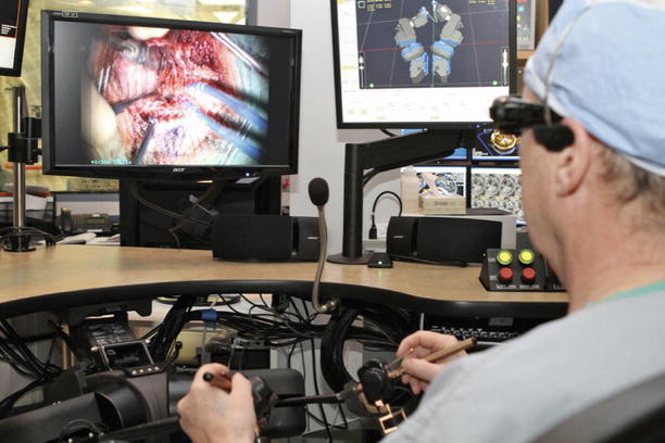
Human-Machine Interface
The human-machine interface recreates the sight, sound, and touch of surgery, while facilitating integration of advanced imaging and surgical planning technologies [38] (Fig. 46.4). Two SONY PMW-10MD Full HD Medical Grade cameras, equipped with 3 one-half-inch (1,920 × 1,080) ExmorTM CMOS sensors, each delivers over two million pixels. Images are then displayed on an LMD-2451MT HD medical monitor that enables surgeons to gain full depth perception and spatial orientation during intricate procedures through clear 3D picture display. Surgeons wear light, comfortable polarized glasses to view the 3D display. These polarized glasses are almost clear and do not interfere with viewing the other workstation displays.