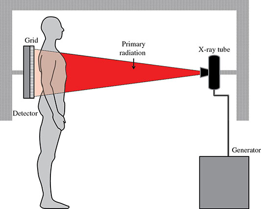
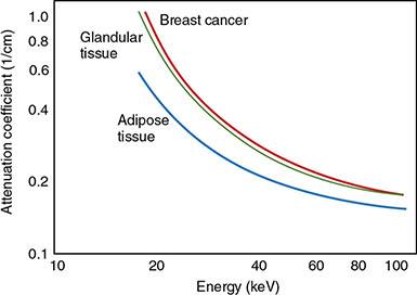
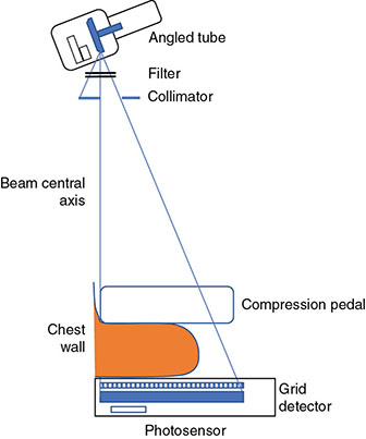
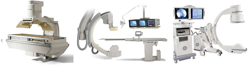
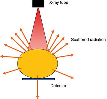
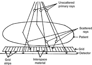
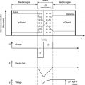
6 Projection X-ray imaging is a modality of medical imaging that involves two-dimensional images of the body, either statistically or dynamically variable in time. It is an essential modality through which a shadowgram of the three-dimensional body part, at a moment of time, is projected via an X-ray beam onto a two-dimensional surface. Images are recorded via detectors positioned at the exit surface of the body. Resulting images are considered satisfactory if enough information is transmitted through the body part such that the features of varying attenuation properties can be seen distinct from one another. This necessitates a sufficient and varied numbers of X-rays emerging from the patient and impinging on the sensor. Depending on the application, both the magnitude and the energy of X-rays are varied to achieve that goal. Projection X-ray imaging consists of three closely related technologies: radiography, mammography, and fluoroscopy. Radiography pertains to the acquisition of static two-dimensional images of nearly all body parts ranging from the main body habitus to extremities and the skull. Mammography extends that application to be specific for breast imaging. The application to breast is distinct because of optimization of the technology for imaging this one region of the body. When projection imaging is extended to the temporal domain, the modality is referred to as fluoroscopy. Fluoroscopy, again with distinct technology and acquisition process, enables dynamic imaging of the body. The foundation of projection X-ray imaging is covered in earlier chapters (Chapters 1–3). In this chapter, we primarily focus on the specific implementation of those foundations in the technology and process of the primary projection X-ray modality, radiography, and its close associates of mammography and fluoroscopy. The formation of projection X-ray image requires a radiation source and a detector in the opposite sides of the body part. This requires a geometrical apparatus referred to as gantry (Figure 6.1). One side of the gantry houses the X-ray tube and the other side houses the radiographic detector. The patient’s body is positioned within the gantry, usually near the detector. A divergent X-ray beam, most commonly in the form of a cone beam, is directed to the detector, passing through the body part and creating a shadow of attenuation differentials from the body. This shadow is recorded by the detector forming the image. Figure 6.1 Basic elements of a projection X-ray system. The radiography X-ray tube contains an adjustable beam-limiting device, made of interleaved plates that define the exact field of exposure. The body part of interest is positioned such that only the anatomy of interest is in the field; no exposure should extend beyond the field of view of the detector. The X-ray source assembly is connected to the gantry such that its location and orientation can be changed for different patient positioning and acquisition angles. However, in any acquisition, its flux should only be directed to the detector (to avoid unnecessary patient exposure). The detector assembly contains the imaging sensor, required electronics, and often a scatter reduction grid, used to limit scattered radiation from the image. The grids come with different geometrical and attenuation specifications and may be stationary or oscillating (see Section 6.4.2). The beam divergence is an important component of projection X-ray imaging as it causes the magnification of the projection X-ray image. The magnification creates three major constraints on the image acquisition. First, if the image is overly magnified, the organs of interest may not fall within the imaging field of view and therefore will not be captured by the detector. Second, the higher magnification can lead to increased blurring because of geometrical factors, e.g. focal spot size. Finally, for sensors that require a certain amount of signal to achieve sufficient image quality, higher magnification may necessitate increased radiation dose to the patient in order to achieve the required signal at the detector [1]. These constraints, in conjunction with the desired field of view, the minimum achievable focal spot size, and expected radiation dose, dictate the proper geometry for any given acquisition in terms of focal spot to detector distance, field of view, and body part to detector distance. If X-rays are assumed to originate from a single point on the target of the X-ray tube, then the magnification of the radiographic image is calculated as If the distance between the target of the X-ray tube and the X-ray detector is constant, then the ratio of the image size to the object size may be increased by moving the object toward the X-ray tube. This is called object shift enlargement (Figure 6.2); in contrast, image shift enlargement maintains a constant distance between the target and the object but moves the detector farther from the object to increase the ratio of image size to object size. Figure 6.2 Magnification in projection X-ray imaging: f is the apparent focal spot of the X-ray tube, SID is source to image representing the distance between the image receptor and the target of the X-ray tube. The amount of enlargement possible without significant loss of image detail is an important consideration in projection X-ray imaging. With the image receptor close to the patient, the blurring of the detector (termed unsharpness in radiographic imaging) is the primary determinant of the visibility of image detail. As the distance between the detector and the patient is increased by object shift or image shift enlargement, the effect of detector unsharpness on the image detail is unchanged. However, the contribution of geometric unsharpness increases steadily with an increasing distance between the patient and the image receptor, i.e. increasing magnification, as per Figure 6.2, At some patient–receptor distance, geometric unsharpness approximately equals detector unsharpness. Beyond this distance, the image detail visibility deteriorates steadily as geometric unsharpness increasingly dominates detector unsharpness. As a general rule, the image should not be magnified beyond the point at which geometric unsharpness and detector unsharpness are approximately equal. This constraint usually dictates the use of a focal spot that has dimensions small enough to minimize the geometric unsharpness when acquiring a magnified view. For any X-ray modality, the X-ray tube should have sufficient heat capacity to provide sufficient X-ray flux; a higher flux enables shorter acquisition time, thus minimizing the likelihood of patient motion during the imaging process. Larger focal spot sizes provide for higher flux but also larger geometrical unsharpness. Thus, there is always a trade-off between temporal and spatial resolution. The tube generator also needs an operating voltage high enough to provide X-rays of the energy needed to penetrate the body part of interest but also low enough to provide sufficient contrast for body features of interest, as lower energies provide for more intrinsic contrast (see Chapter 2). In clinical radiography, the anode heel effect also has two important factors to consider when imaging. The cathode side of the field of view offers higher flux, and as such, the thicker part of the anatomy is best positioned toward the cathode side of the X-ray tube to take advantage of this higher X-ray flux. However, the cathode side also exhibits a larger apparent focal spot size because of the angular perspective of the focal spot from the sensor (Figure 6.3). For this reason, radiographic images exhibit higher spatial resolution toward the anode side of the X-ray tube. Figure 6.3 Schematic of the heel effect and change in the apparent focal spot size in radiography. The above trade-off and considerations provide a variety of constraints that dictate how each application of projection imaging is protocoled. A few examples are provided in Table 6.1. Different protocols also make use of the fact that the detector in radiography can be upright (as for chest imaging), within a table (for abdominal imaging), or tabletop (for extremity imaging), or portable for bedside imaging applications. Table 6.1 Example of typical radiographic protocols used in clinical practice In standard radiography, the body part is positioned as close to the image detector as possible in order to minimize the magnification. However, different regions of the image are always magnified according to their distance from the focal spot. Other considerations include the source-to-image distance (SID), focal spot size, and thickness of the anatomy. If a higher flux of X-rays is needed, a shorter SID can be used (typically 100 cm), but greater distances (typically 180 cm) cause less magnification distortion, which is desirable for some imaging applications. A typical focal spot size in radiography is 1–1.2 mm. If the imaging requires higher sharpness, a smaller focal spot size is used (typically 0.4–0.6 mm). However, smaller focal spots generally have smaller maximum current settings, so there may be higher noise because of reduced X-ray flux that can be obtained without damaging the focal spot or higher exposure time and thus higher potential for motion blur. Typical kilovolts setting in radiography ranges between 60 and 70 kV for extremities (e.g. hand and foot), 80–100 kV for medium size body parts (e.g. skull), and for large body parts (e.g. chest or abdomen) up to 120–140 kV. Higher kilovolts offer higher penetration and lower patient dose (assuming mA is adjusted accordingly) but lower subject contrast (see Chapter 2). In imaging anatomy that is within the main body habitus (e.g. spine, chest, abdomen, and pelvis), the thickness of the body part and the size of the field of view causes a high amount of scattered radiation to be generated, reducing the image quality. For these exams, antiscatter grids are helpful but cannot always be used. Clearly, radiography and medical imaging generally is often an exercise in cost–benefit analysis between many factors with image quality in only one consideration. Mammography is a special radiographic procedure performed to visualize the tissue within the breast. It has the same general characteristics as standard radiography although with certain special provisions optimized to image the unique attributes of breast tissue and pathology. Breasts are primarily composed of soft tissues, which is between adipose and muscle in terms of attenuation. The small attenuation differential necessitates a lower X-ray energy because the differences between tissue types are most pronounced in lower ranges (Figure 6.4) [2]. As such, most mammography systems operate between 25 and 35 kV. Further, the X-ray tube commonly uses molybdenum with options for rhodium and tungsten targets in some systems, because the characteristic energies of these elements fall within the mammography X-ray spectra, offering a high flux of characteristic X-rays within the energies of interest (see Chapter 2). Figure 6.4 Attenuation coefficient of breast tissues as a function of energy. A notable component of mammography is breast compression with a radiotransparent paddle. The compression provides multiple advantages: It reduced the total attenuation through the breast by reducing its thickness. It further reduces the magnitude of generated scattered radiation. Both of these provide for lowering the needed flux of X-rays and thus patient dose. Additional benefits of compression include immobilization of the breast, thus minimizing the potential for motion blur, enabling the use of lower energy X-rays because of the thinness of the breast, providing better imaging of the breast tissue close to the chest wall and reducing magnification unsharpness and geometrical distortion. The mammographic tube also uses a small focal spot (typically 0.3 mm) because mammography must identify the fine spatial details that are often characteristic of malignancy (small tumor features or microcalcifications). The small focal spot achieves higher resolution depictions of such details. Mammography frequently includes magnification imaging for enhancing details even further within limited target areas of the breast. Magnification radiography exploits the aforementioned properties of a divergent X-ray beam to intentionally form an image larger than the physical size of the body part. In that mode, typically, a 0.1 mm focal spot is used to manage the enhanced focal spot blur due to higher magnification. The SID for mammography is relatively short compared to general radiographic procedures, e.g. 65 cm, and the geometrical configuration is highly conformed to the anatomical structure of the breast and chest. The breast anatomy that must be imaged includes the tissue immediately adjacent to the chest wall, so the gantry is configured for the maximum coverage at the chest wall by tilting the tube and placing the central axis of the beam directly parallel with the chest wall. In that way, the entire breast tissue accessible by the geometry can be captured in the image. In addition, by placing the central axis of the beam directly parallel with the chest wall, the divergent beam is parallel with the chest wall reducing any radiation that does not intersect the detector and entering the chest (Figure 6.5). Because of this configuration, the photon flux is largest at the chest wall, where the anatomy may be thickest, but the apparent focal spot is also larger. Conversely toward the nipple, there is better resolution and smaller photon flux. Figure 6.5 Schematic of a mammographic imaging system. Fluoroscopy provides real-time projection imaging of a body part. The procedure is often used in clinical applications where a dynamic process needs to be visualized. That includes the transient opacification of blood vessels in angiography, the transition of a contrast bolus through the gastrointestinal (GI) track, or interventional procedure where the location of an inserted apparatus or probe needs to be discerned with respect to the penetrated anatomy. The fluoroscopic system comes with diverse configurations, ranging from table-based units, potable c-arms that can be moved to the patient and positioned as needed around the patient, to c-arms mounted to the examination room floor or ceiling (Figure 6.6). C-arm systems mounted within a room usually provide greater maneuverability and imaging capabilities than portable systems, and some come equipped with multiple X-ray tube/detector configurations (i.e. bi-plane c-arms) that enable improved visualization. Figure 6.6 Diversity of gantry configurations used in fluoroscopy. Given the diversity of applications, body parts, and patients, fluoroscopy systems need to dynamically adjust the X-ray energy and flux to provide sufficient X-ray penetration and image quality as the area being imaged changes, which often occurs in a single fluoroscopy examination. This requires a real-time feedback circuitry in the fluoroscopy systems. Further, the adaptation of the flux to the imaging needs to follow certain predetermined functions. For example, as the attenuation of a penetrating body part increases, a system might proportionally increase the milliamperes only, the kilovolts only, or a combination of the two. The resulting images offer different levels of signal, contrast, or noise, based on the adaptation function, often configurable by service. This process of controlling the X-ray technical factors to meet a preset detector imaging needs is called automatic brightness control (ABC) (see Section 6.4.3.2.1). The traditional detector technology for fluoroscopy is an image-intensifier (II) tube. Newer systems use flat panel detector (FPD) technology [3,4]. These technologies are distinct and as such offer differing features to fluoroscopic applications. For example, in the case of image resolution, the II resolution can be as high as 5 lp/mm but is variable as a function of the magnification. The resolution for FPDs in contrast is around 2 lp/mm. With II detectors, the ABC system (see Section 6.4.3.2.1) increases the exposure rate with magnification to ensure consistent brightness. An advantage of FPDs is that they do not have distortion artifacts (i.e. pincushion and S-distortion) that are an issue with II detectors (see Section 6.4.3.2.1). FPD systems also use pixel binning to reduce noise, albeit negatively affecting image resolution. Although in radiographic procedures it is possible to manage the dose by adjusting ray tube milliamperes and kilovots, as well as the source to skin distance, fluoroscopic dose reduction strategies take into account also the total fluoro time. Fluoroscopy X-ray tube can produce a continuous beam, so patient exposure can accumulate over long exposure times. By regulation, these systems must provide a sound alert after five minutes of total fluoroscopy time and the maximum entrance exposure rate must not exceed 10 R/min for most fluoroscopy studies, although most fluoroscopy systems can operate in high-dose or low-dose rate modes. The high-dose mode allows entrance exposure rates up to 20 R/min but requires an audible signal while in use. The low-dose modes are implemented in most new systems with the capability to select different dose rates for different sizes by adding beam filtration to reduce radiation dose, especially for pediatric studies. Although the production of X-rays can be continuous, human perception can interpret motion that varies with intensity and contrast, with the fastest variation being 50–90 Hz [5]. Most displays limit the rate to only 30 frames per second (fps). With this frame rate, any motion that occurs within a 33 ms time window will be blurred in an image. Yet, for most physiological functions, motion faster than this is uncommon, so most fluoroscopy systems operate in pulse mode. In pulse mode, the X-ray tube produces a series of short pulses (typical between 1 and 10 pulses/s), resulting in reductions in dose and image blur. As an example, a continuous mode procedure that produces a 30 fps with 33 ms per frame at 2 mA of X-ray tube current can be replaced with a pulse mode procedure at 30 fps with 10 ms per frame and 6.6 mA of tube current. Lower frame rates are encouraged if lower temporal resolution can be tolerated. For example, when guiding catheter from femoral artery to aortic arch simply by reducing the frame rate from 30 to 7.5 fps results in a 75% reduction is patient dose. The use of flat panel digital technology in fluoroscopy has enabled other dose management strategies. One strategy is temporal frame averaging, which reduces image noise at the cost of a tolerable reduction in temporal resolution, and introducing image lag, but enabling reduction in mA and thus patient dose. The displayed image is obtained by averaging two or more previous frames. Other temporal image filtering can also be applied to minimize lag if that is needed for the study. As most applications of fluoroscopy are for interventional purposes, radiation protection of the personnel becomes essential. In fluoroscopy, the primary source of exposure to medical personnel is the scattered radiation from the patient. Figure 6.7 shows how the scattered radiation is higher at the tube side of the gantry. Physician and radiographer exposure may be reduced by simply operating fluoroscopy device with the tube positioned below the patient. The dose rate is also inversely proportional to the square of the distance to the source; staying at distance from the patient during the exposure (if it is possible) reduces the operator’s dose. Therefore, standing behind others if a direct line of sight to the patient is not essential. All persons present in the room during the procedure must wear a lead apron (equivalent to 0.5 mm Pb), and other lead strips may be positioned between the patient and the operators to shield the scattered radiation. Figure 6.7 Pattern of scattered radiation from the patient body, subjecting the operator to a higher level for secondary irradiation when the operation is located in the tube side of the gantry. The X-ray tubes used in projection X-ray imaging generally follow the details and specifications delineated in Chapter 1. In radiography, there is a need to acquire static images with a least amount of motion and with sufficient penetration. This necessitates the production of X-rays with high flux (i.e. high milliamperes) and high energy (i.e. high kilovolts). As a result, most radiographic tubes and generators need to be high powered. A typical radiography tube generator is 60–120 kW. The focal spots are typically 1.2 mm in size, nominally, with higher resolution imaging offered with small focal spots, typically 0.4–0.6 mm in size. The tube is equipped with an adjustable beam-limiting device that adjusts the field size to a range of typically 5 cm × 5 cm to 43 cm × 43 cm for typical SIDs of 100–180 cm. In mammography, the power needs are more modest, as photon energy is kept at low levels to extenuate tissue contrast. Also, the breast is reasonably immobile because of the use of breast compression. As such, lower maximum milliampere settings are tolerated. The typical mammographic tube generator power is 3–10 kW. Mammography uses a small focal spot, typically 0.3 mm in size for standard views and typically 0.1 mm focal spot for magnification. The mammography systems are equipped with a range of beam-limiting devices, each of which provides for a specific field of view ranging from 18 cm × 24 cm to 24 cm × 30 cm for the typical SID of 65 cm. In fluoroscopy, the power needs to vary widely. For portable c-arm applications, the power is generally low within 3–30 kW. For vascular applications where there is more potential for excessive motion and image noise needs to be low, a higher power rating is needed. Fluoroscopy systems of this type are usually in use in interventional and surgical suits. Focal spot sizes range from 0.6 to 1.2 mm. The bream-limiting devices are similar to that of radiography with field size adjustment functionality. The beam shape, however, is not limited to rectangular shape, and circular or other shapes are possible. One of the major challenges in projection X-ray imaging is the ever-presence of scattered radiation, either Rayleigh or Compton (see Chapter 1). Scattered radiation creates a “fog” in the image, increasing noise and reducing contrast. As both primary (i.e. wanted) and scattered (i.e. unwanted) radiation impinge on the detector after passing through the patient, the scattered radiation can conceal the useful information by diluting the information content. Furthermore, scatter is often unevenly distributed across the imaging field of view; thus, the impact on contrast and noise varies from region to region. The deteriorating influence of scattered radiation is present in all applications of projection X-ray imaging, radiography, mammography, and fluoroscopy. Radiation scatter is proportional to the volume of tissue exposed to the X-ray beam, so confining the X-ray beam to the region of interest can significantly reduce the scatter (simultaneously reducing the patient dose) [6]. As such, proper collimation of an X-ray beam with the beam-limiting device is essential to the production of high-quality projection images. Much of the scattered radiation can be removed by a radiographic grid between the patient and the X-ray detector. A grid typically consists of strips of a dense, high-Z material separated by a material that is relatively transparent to X-rays. The grid prevents radiation that is not aligned with the primary beam from reaching the detector (Figure 6.8). Figure 6.8 A radiographic grid is used to remove scattered radiation emerging from the patient. Most primary photons are transmitted through the grid without attenuation. Ideally, the strips in a radiographic grid should not be visible in the radiographic image. Additionally, the strips should be completely opaque to scattered radiation and should not release secondary radiation of its own (e.g. fluorescence) as scattered X-ray photons are absorbed. These requirements are reasonably satisfied by lead foil about 0.05 mm thick, and this material is commonly used. However, the grid lines can still leave artifacts in the images ranging from directly visible lines, moiré patterns, or broad nonuniformity in the images (see Section 6.4.2.1). The material between the grid strips may be aluminum, fiber, or plastic. Although fiber and plastic transmit primary photons with minimal or no attenuation, grids with aluminum interspaces are structurally stronger. Also, grids with aluminum interspaces may absorb scattered radiation that escape the grid strips [7]. However, grids with improved attenuation also necessitate higher radiation dose to the patient to achieve a desired signal magnitude at the detector. Radiographic grids are available commercially with parallel or focused grid strips in either linear or crossed configurations (Figures 6.9 and 6.10). When a focused grid is positioned at the correct distance from the target of an X-ray tube, lines through the grid strips are directed toward a point or focus on the target. With a parallel grid positioned at a finite distance from an X-ray tube, more primary X-rays are attenuated along the edge of the radiograph than at the center. Consequently, the detector signal decreases slightly from the center to the edge of a radiograph exposed with a parallel grid. Thus, the uniformity of the detector signal is improved in a radiograph exposed with a focused grid, provided that the grid is positioned correctly. Figure 6.9 Focused and parallel grids. Figure 6.10 Types of focused and parallel grids. A linear grid is constructed with all parallel or focused grid strips in line (Figure 6.10). A crossed grid is made with the strips in one grid perpendicular to those in the other. In most situations, a crossed grid removes more scattered radiation than does a linear grid with the same grid ratio because a linear grid does not absorb photons scattered parallel to the grid strips. However, a linear grid is easier to use in situations where proper alignment of the X-ray tube, grid, and X-ray detector is difficult (see Section 6.4.2.1). Linear grids are generally characterized in terms of the ratio of the width of the interspace material to its height (grid ratio, Figure 6.11), grid frequency (number of lines per unit distance), and grid focus distance. Figure 6.11 The grid ratio r is the height h of the grid strips divided by the distance between the strips. The grid ratio is calculated as where h is the height of the grid strips and d is the distance between grid strips. The grid ratio of a crossed grid is r1 + r2, where r1 and r2 are the grid ratios of the linear grids used to form the crossed grid. Radiographic grids with grid ratios greater than 16 are available commercially. However, ratios of 8–12 are most common because the removal of scattered radiation is increased only slightly with increasing grid ratios. Also, grids with a high grid ratio require more precise alignment and a greater patient exposure to radiation. The effectiveness of a radiographic grid for removing scattered radiation as a function of grid ratio is illustrated in Figure 6.12. Figure 6.12 The transmission of scattered radiation decreases rapidly for small grid ratios, but above 8, the effect is less pronounced. Source: Courtesy of S. Ledin and the Elema Shönander Co. Grid ratios provide proportionally improved radiographic contrast, with higher values for lower energy X-rays (Table 6.2). Note that this decrease is reflective of subject contrast as captured by the detector. Correspondingly, the grid’s contrast improvement factor is defined as the ratio of the maximum radiographic contrast with the grid to the maximum contrast without the grid; the factor expresses the effectiveness of different grids at removing scattered radiation. The contrast improvement factor for a particular grid varies with the thickness of the patient and with the cross-sectional area and energy of the X-ray beam. In order to impose a standard metric for comparison, the contrast improvement factor is usually measured with a water phantom, 20 cm thick, irradiated by an X-ray beam generated at 100 kVp [9]. The image contrast-to-noise ratio (CNR) is directly influenced by this contrast, even when the contrast of an image can be adjusted in digital imaging systems. Table 6.2 Relative increase in radiographic contrast and radiation exposure for grids with different ratiosa aThe thickness of the grid strips and interspaces were identical for all grids. Source: From Characteristics and Applications of X-ray Grids. Cincinnati, Liebel-Flarsheim Co., 1968 [8]. Used with permission. The radiation exposure of the patient increases with the grid ratio because the radiation flux must be increased to have sufficient primary X-ray photons reach the detector. This is related to the selectivity of a grid defined as the ratio of primary to scattered radiation transmitted through the grid. One popular but rather ambiguous description of grid effectiveness is the Bucky factor (named after the designer of the first radiographic grid), defined as the exposure to the detector without the grid divided by the exposure to the detector with the grid in place when a wide X-ray field emerges from a thick patient. This factor is obviously highly dependent on patient-specific characteristics. Thus, a standard condition, such as the one noted above, should be applied in its characterization. A crossed grid removes scattered radiation more effectively than a linear grid with an equal grid ratio, with associated increase in patient exposure. Grid frequency is another important parameter. Grid line creates a shadow in the radiographic images. These shadows can be blurred by moving the grid or by image processing. Grids with many strips per unit length produce shadows in the radiographic image that are easier to remedy or are not as easily visualized. Typical grid frequencies are 20–80 strips cm−1 (80–200 in.−1), with higher frequency ratios used in higher resolution applications. Also, the lead content of the grid (in units of grams per square centimeter) is sometimes stated along with the grid ratio and frequency. Grids may be described as heavy or light, depending on their lead content. Considering the prevalence of scattered radiation in X-ray imaging, the selection of a grid has a substantial influence on the resultant image. To summarize, high grid ratios eliminate the scatter most effectively, but the concurrent reduction in the primary beam must be offset with a greater flux of X-rays, which results in increased patient dose. Notably, grids with higher ratios are also more susceptible to positioning-related problems and artifacts. A central issue with the use of grid is the shadow of the grid structure in the image, which, if left unmitigated, is distracting and can sometimes interfere with the identification of small structures such as blood vessels and bone trabeculae. One common remedy is moving the grid. A moving grid (a so-called Potter–Bucky diaphragm) removes the distracting grid strips by blurring their image across the detector. Early Potter–Bucky diaphragms moved in one direction only, but modern moving grids make several transits back and forth during an exposure. The linear distance over which the grid moves is small (1–5 cm), and as such does not cause significant off-center cutoff (see below). However, the movement must take place within the brief exposure. Also, the motion of the grid must not be parallel to the grid strips, and it must be adjusted to prevent synchronization between the position of the grid strips and the rate of pulsation of the X-ray beam. The direction of motion of the grid changes very rapidly at the limits of grid travel, so the dwell time of the grid at these positions is insignificant. The moving grid does not interfere with the photons traveling in a straight line from the focal spot to reach the image receptor because of their high speed. A typical moving grid travels at a maximum rate of 15 cm/s, and it takes X-ray photons only 3 ns to travel the 100 cm from the X-ray tube to the image receptor. During this time, a grid moving at 15 cm/s will have traveled only 5 Å (the width of five atoms). In imaging detectors with high spatial resolution, the grid artifact may only be eliminated by oscillating the grid during the image acquisition, essentially blurring the grid lines. As such, it is a natural choice in many applications, but it is not the only method to mitigate grid line artifacts. In portable applications, a moving apparatus is not practical. The maintenance cost for reciprocating grids and their poor efficiency for removing the image of grid strips during short exposure times are also reasons for alternative methods. The development of high-frequency grids has reduced the need for moving grids. Essentially, if the grid frequency is higher than their resolving power of the digital sensor, the line artifact may be avoided without the oscillating motion. In most modern digital FPDs, the resolution is higher or in the same order of magnitude to that of the grid frequency. Short of using an oscillating grid method for grid line reduction, for many of these systems, the grid lines are eliminated by two common image-processing methods. The first method captures an image of the grid during detector calibration. This image is stored and during the preprocessing workflow subtracted from the acquired clinical images, effectually erasing the artifact. This requires perfect reproducible positioning of grid with respect to the detector; if the grid is misplaced between when the calibration image and the actual image are captured, not only the grid lines would not be eliminated, they will be enhanced. Alternatively, the grid lines can be eliminated by using a band-pass filter (see Chapter 3) in the direction perpendicular to the direction of the grid lines. In digital systems, poor or partial elimination of grid line artifact can lead to an interference between the periodic pattern of the grid and that of the image pixels, sampling inherent to digital imaging. This interference causes aliasing, where the higher frequency component of the grid get reflected as a low-frequency periodic pattern in the image, known as a moiré pattern (see Chapter 3). In addition to line artifacts, there can be an uneven loss of primary radiation caused by improper alignment of a radiographic grid, which causes grid cutoff. With a parallel grid and the cone beam of X-rays used in radiography, cutoff occurs near the edges of a large field because grid strips intercept many primary photons along the edges of the X-ray beam. The width of the shadow of grid strips in a parallel grid increases with their distance from the center of the grid (Figure 6.13). Figure 6.13 Cutoff of primary X-ray photons with a parallel grid. The use of a focused grid at an incorrect target–grid distance also causes grid cutoff, specifically axial decentering or off-distance cutoff (Figure 6.14). The detector signal with off-distance cutoff decreases from the center of the field outward, and the variation in detector exposure increases with the displacement of the grid from the correct target–grid distance. However, the effect is not problematic until the displacement exceeds the target–grid distance limits established for the grid. These limits are narrow for grids with high grid ratios and wider for grids with smaller ratios. Finally, the effects of off-distance cutoff are more severe when the target–grid distance is shorter than that recommended and less severe when the target–grid distance is greater. Figure 6.14 Off-distance cutoff with a focused grid. Lateral decentering or off-center cutoff occurs when X-rays parallel to the strips of a focused grid converge at a location that is displaced laterally from the target of the X-ray tube (Figure 6.15). Off-level cutoff results from tilting the grid (Figure 6.16). Both off-center and off-level cutoff cause an overall reduction in detector signal (image nonuniformity across the image). The importance of correct alignment of the X-ray tube, grid, and detector increases with the grid ratio. Figure 6.15 Off-center cutoff with a focused grid. Figure 6.16 Off-level cutoff with a focused grid. The choice of a radiographic grid for a particular examination depends on factors such as the anticipated amount of primary and scattered radiation emerging from the patient, X-ray energy, range of radiographic techniques possible by the X-ray generator, and difficulty of aligning the X-ray beam with the grid. In portable projection imaging (such as bedside imaging), beam grid alignment is often difficult; these applications thus often use lower grid ratios with a consequential reduction in scatter radiation removal and therefore poorer image quality. To avoid the grid-induced complications of line artifacts, grid cutoff, and increased dose, a number of nongrid imaging alternatives have been considered or are in use. Those include the use of an air gap, slot-scan technology, or image-processing corrections. In the air gap technique, the amount of scattered radiation reaching the detector is reduced by increasing the patient detector distance. This increases image magnification. Obviously, if this magnification causes the anatomy of interest to be projected into an area larger than the physical size of the image detector, this method cannot be used. The radiation dose to the patient can also increase per magnification. Further, the air gap technique increases the focal spot blur, necessitating the use of smaller focal spots. For thicker body parts, where this maxes the mA setting of the generator, this necessitates lengthening of the exposure time and consequently the potential for patient motion artifacts. In the slot-scan technique, a slit in an otherwise radiation-opaque shield moves within the field of view in synchrony with a scanner fan beam of X-ray (Figure 6.17). The shield intercepts scattered radiation before it reaches the detector, which is also a narrow linear array [10]. This method can be highly effective provided that the fan beam can be precisely shaped and targeted to the detector, avoiding wasted radiation beyond the detector that only contributes to patient dose and not the image signal. The fan and the slit should also be narrow enough (1 cm or less) to effectively eliminate forward scattering radiation. Finally, the scan length is longer than a standard radiographic acquisition, so the patient must remain still during the acquisition to avoid motion artifacts, although such motion artifacts, if they occur, can be limited to only small bands within the image [11]. Figure 6.17 Comparison of full-field (a) and slot-scan (b) projection imaging. Finally, image-processing techniques are used to remedy the influence of scattered radiation on projection images. These methods are effective in reducing the nonuniformity in the image associated with the uneven distribution of scatter signal. However, the loss of image CNR from the presence of scatter fog cannot be overcome with postprocessing techniques. For most of its history, detecting X-ray signal with an analog detector, namely X-ray film, has been the primary means to capture static projection imaging, radiography, and mammography. In the developed world, film has largely been replaced by digital technology. However, film is still used in medical practice worldwide. Further, even in the digital era, film technology has created a lasting effect in the way X-ray images are rendered, understood, and interpreted, so it is an important foundation to understand. The X-ray film can have an emulsion on one side (single-emulsion film) or both sides (double-emulsion film) of a transparent film base that is about 0.2 mm thick (Figure 6.18). Single-emulsion systems are commonly used in mammography, whereas double ones are used in radiography. The emulsion is composed of silver-halide granules, usually silver bromide, that are suspended in a gelatin matrix. The emulsion is covered with a protective coating (T coat) and is sensitive to visible and ultraviolet light and to ionizing radiation. Single-emulsion film is less sensitive to radiation and is used primarily when exceptionally fine detail is required in the image (such as for mammography). The base is either cellulose acetate or a polyester resin. Intensifying screens may be added to make the film most sensitive to the wavelengths of light the screens emit. Nonscreen film is designed for direct exposure to X-rays and is less sensitive to visible light. However, virtually, all film used in diagnostic radiology is designed to be used with intensifying screens. Figure 6.18 Cross section of an X-ray film. The base is cellulose acetate or a polyester resin, and the emulsion is usually silver bromide suspended in a gelatin matrix. Electrons in the granules of silver bromide in the emulsion of an X-ray film are released after absorbing energy when the film is exposed to ionizing radiation or to visible light. These electrons are trapped at sensitivity centers in the crystal lattice of the silver bromide granules, where they attract and neutralize mobile silver ions (Ag+) in the lattice (small quantities of metallic silver are deposited in the emulsion, primarily along the surface of the silver bromide granules). Although these changes in the granules are not visible, the deposition of metallic silver across a film exposed to an X-ray beam is a representation of the radiation impinging on the film. This information is captured and stored as a latent image in the photographic emulsion. The latent image on the film must be chemically processed to form the image. First, the film is placed in a developing solution, where the latent image induced by the radiation serves as a catalyst for the deposition of metallic silver on the film base. In the next step of fixation, granules that were unaffected during exposure of the film are removed by sodium thiosulfate or ammonium thiosulfate in the fixing solution. This solution also contains potassium alum to harden the emulsion and acetic acid to neutralize residual developer on the film. The degree of blackening of a region of the processed film depends on the amount of free silver deposited in the region and, consequently, on the number of X-rays absorbed in the region. The amount of light transmitted by a region of processed film is described by the transmittance T,
Projection X-ray Imaging
6.1 Introduction
6.2 Projection X-ray Setup


Protocol
Body thickness (cm)
SID (cm)
Grid
kV
Typical mA
Typical exposure time (s)
Maximum mAs or mA
Chest
23
183
12 : 1
120
4.7
0.001
5
Cervical spine
13
100
12 : 1
70
22
0.001
31
Hand
5
100
None
60
2.5
0.001
7
Breast (mammography)
4.5
65
5 : 1
28
60
0.6
75
Cardiac fluoroscopy
23
100
8 : 1
90
10
0.006 per pulse
18 mA
6.3 X-ray Projection Modalities
6.3.1 Radiography
6.3.2 Mammography
6.3.3 Fluoroscopy
6.4 Key Components of Projection X-ray Systems
6.4.1 X-ray Tube and Generator
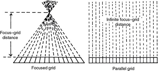
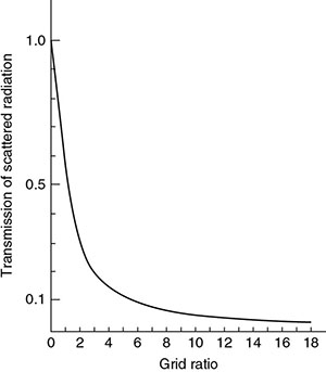
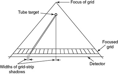
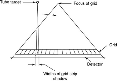
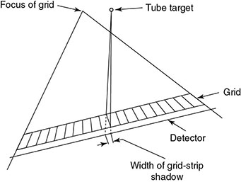
6.4.2 Antiscatter Grid


Type of grid and grid ratio
Improvement in contrast
Increase in exposure
70 kVp
95 kVp
120 kVp
70 kVp
95 kVp
120 kVp
None
1
1
1
1
1
1
5 linear
3.5
2.5
2
3
3
3
8 linear
4.75
3.25
2.5
3.5
3.75
4
12 linear
5.25
3.75
3
4
4.25
5
16 linear
5.75
4
3.25
4.5
5
6
5 cross
5.75
3.5
2.75
4.5
5
5.5
8 cross
6.75
4.25
3.25
5
6
7
6.4.2.1 Grid Artifacts

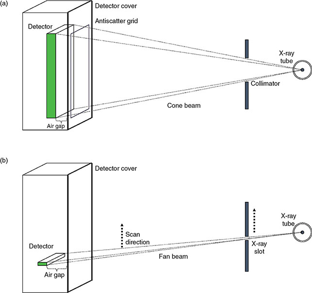
6.4.2.2 Alternatives to Grid
6.4.3 Analog Imaging Detectors
6.4.3.1 Screen Film
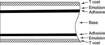
6.4.3.1.1 Photographic Process
6.4.3.1.2 Optical Density and Film Gamma

Related posts:
![]()
Stay updated, free articles. Join our Telegram channel


Full access? Get Clinical Tree


