Pseudo-Continuous Arterial Spin Labeling
David C. Alsop
Ajit Shankaranarayanan
Continuous labeling of inflowing arterial blood as it flows past a selected labeling plane is an elegant and advantageous strategy for arterial spin labeling (ASL).1,2 As introduced in Chapter 15, continuous labeling offers a number of advantages over pulsed labeling. Perhaps most important is the increased signal and signal-to-noise ratio produced by continuous labeling relative to pulsed labeling.3,4,5 To understand the reason for this greater signal, consider the geometry shown in Figure 17.1. Suppose we wish to label blood for a period of time, T1. For the continuous labeling approach, we would simply apply labeling just below the imaged slab for T1. In this case, all the blood that passes through the labeling plane during this time would form the bolus of labeled blood. For pulsed labeling, on the other hand, we would invert a thick slab once and the bolus of labeled blood would be defined spatially at one time. It is important, for pulsed labeling, to invert a very thick slab so unlabeled blood does not flow across the superior end of the slab during T1. Initially, the labeled blood will be very similar for the two techniques. But as the labeling time continues, the pulsed labeling crossing into the imaged region will decay with T1 as blood has to travel from the proximal end of the labeling slab to the distal end, while for continuous labeling, the labeling remains at constant strength because all blood is labeled just before it enters the imaged volume. The end result is up to almost three times more labeled signal and at least twice the signal-to-noise ratio of pulsed labeling (Fig. 17.2). Because ASL is a relatively low signal-to-noise ratio technique, this substantial improvement is a major advantage.
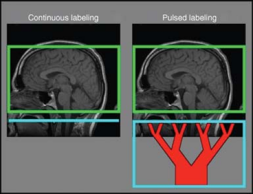 FIGURE 17.1. The geometry of continuous and pulses labeling for arterial spin labeling (ASL) of the brain. Continuous labeling (left) inverts arterial blood as it passes a selected labeling plane (blue line) close to the volume of tissue being imaged (green box). Conversely, in pulsed labeling (right) one must invert a large volume of tissue at once in order to achieve labeling of a sufficient quantity of blood to resemble a bolus and, in turn, to produce a measurable ASL effect (blue box). Because the labeled blood takes time to travel from the proximal end of the box across to the distal end of the box, substantial loss of signal from T1 decay occurs. This is the cause of reduced signal and signal-to-noise ratio with pulsed ASL relative to continuous ASL. |
Continuous ASL (CASL) has a number of advantages beyond higher raw signal. As explained below, ASL allows great flexibility of labeling timing that enables tighter control over vascular signal contamination and transit time effects and even enables more complex labeling strategies, such as Hadamard encoding of labeling time,6 which allows more optimal measurement of flow kinetics. An additional advantage of CASL is that requirements for homogenous magnetic gradient and magnetic fields are modest because labeling is performed in close proximity to the tissue of interest. In pulsed ASL, labeling of a sufficiently long bolus of blood requires inverting tens of centimeters away from the imaged volume. Unfortunately, in many scanners that are optimized for targeted scanning of limited volumes—or even short and wide bore scanners—radiofrequency (RF), gradient, and magnetic field quality drops rapidly with distance from isocenter. Finally, CASL can be used to perform highly localized inversion labeling of individual arteries.7 Although pulsed strategies for vessel selective labeling have been reported,8 continuous approaches have shown indications of sensitivity and localization advantages.9
Realizing all the advantages of continuous labeling in a practical approach has been a challenge. The off-resonance RF power used to achieve continuous labeling can introduce undesirable systematic effects unrelated to blood flow. Magnetization transfer (MT) and even direct T2-related saturation occur in the presence of off-resonance saturation.10 MT can cause huge errors in ASL measurements if not well compensated during the control image, and even when well compensated, it shortens the effective T1 relaxation time of tissue, complicating quantification and reducing sensitivity.4 Continuous labeling usually requires long periods of RF power application that exceed the capabilities of RF hardware on most scanners and also deposits substantial RF power in the subject. Finally, efficiency of inversion is never perfect and any loss of efficiency decreases
the signal-to-noise advantages relative to pulsed inversion techniques.11
the signal-to-noise advantages relative to pulsed inversion techniques.11
 FIGURE 17.2. Simulations of the relative signal level (left) and signal-to-noise ratio per root averaging time (right) for continuous arterial spin labeling (CASL) and pulsed ASL (PASL). CASL has higher signal and signal-to-noise ratios. A transit time and wait before imaging of 1.5 s was assumed and image acquisition time was neglected. |
Fortunately, innovations in labeling and equipment continue that enhance the performance and flexibility of CASL and make possible improving image quality, enhanced sensitivity, and additional applications of ASL beyond perfusion.
Pseudo-Continuous Arterial Spin Labeling
Pseudo-continuous ASL (pcASL) is a pulse sequence strategy that can achieve continuous labeling without special hardware.12 Before describing pcASL, it is helpful to have some intuition for the basic principle of flow-driven adiabatic inversion. Adiabatic inversion has been used in nuclear magnetic resonance systems for many decades and long precedes the use of pulsed acquisition magnetic resonance. It involves applying RF whose frequency is changed with time. Because of the frequency sweep, the rotation angle is not longer but simply proportional to the amplitude and duration of the pulse. In fact, adiabatic inversion pulses are often used in magnetic resonance imaging (MRI) to produce an inversion that is insensitive to variations in the RF amplitude.13 Flow-driven adiabatic inversion uses an applied magnetic field gradient combined with the motion of blood along an artery. As the blood water spins flow along the magnetic field gradient, the precession frequency changes and thus it automatically performs the frequency sweep needed for adiabatic inversion.1,2 This adiabatic inversion process is described in more detail in the following DID YOU KNOW THAT box, although readers who wish to skip these details can continue.
Adiabatic inversion is based on the principle of a temporary steady state, before T2 and T1 decay occur, when constant off-resonance RF is applied. Consider the drawing on the left in Figure 17.3. It shows the RF and spin magnetization in the reference frame rotating at the RF frequency. In the rotating frame of the RF, the off-resonance frequency relative to the spins will cause transverse magnetization to rotate (or precess) around the z-axis at the off-resonance frequency.
Why is this so? Remember that in the real world (where we are not spinning at megahertz) there is a very large magnetic field along the z-axis and the spins precess at very high frequency. When the precession is viewed from a rotating frame, the precession slows down. To represent this slower precession physically, the magnetic field in the rotating frame must be reduced. The total magnetic field in this rotating frame is the vector addition of the reduced magnetic and RF fields. In general, the combination of RF and off-resonance will send the magnetization on an oscillating path over time. Spins will precess around the effective field. If the spins are pointing almost along the effective field, they will precess in a very tight cone, and if they are exactly along the effective field, they are in a temporary steady state.
Adiabatic inversion works on the principle that once spins are pointing along the effective field, they will tend to follow it if the effective field is slowly rotated.
Why is this so? Suppose the effective field rotates in a small angle. The spins will now be pointing slightly away from effective field and will now precess around
the field, keeping a very tight angle. If the precessions are fast relative to the rotations, any offsets will average out and the spins will just follow the field.
the field, keeping a very tight angle. If the precessions are fast relative to the rotations, any offsets will average out and the spins will just follow the field.
Adiabatic inversion is achieved by slowly rotating the effective field direction by 180 degrees from aligned with the main magnetic field direction to pointing in the opposite direction.
Suppose one starts at a very large frequency offset and the RF is very small. The effective field is nearly along the z-axis. Starting with equilibrium z-magnetization, the spins will already be aligned with the effective field. If one gradually increases the RF amplitude while reducing the off-resonance frequency, the effective field will begin to rotate toward the transverse plane (Fig. 17.3). As we continue to sweep the frequency to and then past the resonant frequency, the effective field rotates past the transverse plane and toward inversion. Slowly turning off the RF amplitude will then complete the rotation of the effective field to the negative z-axis. The magnetization will follow the rotation of the field and become inverted. Note that unlike standard inversion, adiabatic inversion does not depend on the exact amplitude of the RF. Adiabatic pulses are familiar to those in MRI, where they are used for their insensitivity to RF amplitude errors. Adiabatic inversion is also the key to continuous labeling.
The adiabatic inversion process can be used to produce a continuous inversion of flowing blood. Implementation simply requires applying a constant magnetic field gradient along the flow direction and a constant RF. The RF is chosen so magnetization at the desired labeling plane is on-resonance when the gradient is turned on. Under these conditions, magnetization far upstream from the labeling plane will have a large off-resonance that gives an effective field along the z-direction (as shown in the sidebar text). As flow carries the magnetization upstream, the effective field decreases and the effective field rotates to the transverse plane at the labeling plane. Continued flow then inverts the magnetization.2
 FIGURE 17.3. Adiabatic inversion of magnetization by a frequency swept pulse as viewed in the rotating frame of the radiofrequency (RF). A: In the reference frame rotating at the RF frequency, the RF magnetic field (B1) appears constant. Because the RF is slightly different from the precession frequency of the magnetization (M), the spins behave as if a small magnetic field (ΔB0), is present along the main magnetic field direction. Magnetization precesses around the effective magnetic field (white vector: Beff), which is the vector sum of the RF and off-resonance field. B: Inversion is achieved by sweeping the frequency of the RF from above to below the magnetization precession frequency. This sweep rotates the effective field from along to against the main magnetic field direction. Magnetization follows the effective field because rapid precession keeps it close to the effective field direction. |
As introduced earlier, this continuous inversion approach poses some challenges for ASL. The off-resonance RF causes systematic saturation of tissue in the imaging region (upstream from the labeling plane) that complicates multislice imaging and quantification. Application of continuous RF is also not possible with most RF amplifiers for clinical imagers. These RF amplifiers take advantage of the increased power and cost-efficiency when operated in a pulsed-only mode. Most clinical RF amplifiers are not built to be operated in continuous mode and drive a big volume coil (e.g., body coil). One solution to both of these problems is to apply the labeling RF using an additional coil driven by an additional RF amplifier capable of continuous operation.14,15 If the coil is small enough (i.e., limited reach) and
far enough from the imaging volume, off-resonance saturation can be eliminated. Although there are some advantages to this hardware approach and RF amplifier solutions for lower power continuous operation are not particularly expensive, pulse sequence strategies (i.e., software solutions without extra coil requirements) that can address the challenges of continuous labeling can be more easily distributed and employed.
far enough from the imaging volume, off-resonance saturation can be eliminated. Although there are some advantages to this hardware approach and RF amplifier solutions for lower power continuous operation are not particularly expensive, pulse sequence strategies (i.e., software solutions without extra coil requirements) that can address the challenges of continuous labeling can be more easily distributed and employed.
Some early pulse sequence strategies addressed many of the challenges of continuous labeling and enabled initial evaluation of CASL in clinical applications.16 Unfortunately, these approaches still required continuous RF, something available only in a limited fashion on particular hardware configurations. More recently, a modified strategy for continuous labeling that is fully compatible with existing scanner hardware has made possible rapid distribution and evaluation of continuous labeling. This pseudo-continuous labeling approach achieves continuous labeling with pulsed RF and gradients.12
Pseudo-continuous RF draws upon intuition drawn from continuous labeling. The basic principle of pcASL is to break up the constant RF and gradient of continuous labeling into short pulses with gaps between them. A problem with discrete pulses, rather than continuous RF, is that aliasing of labeling slices can occur for the RF just as it occurs, for example, in the discrete gradient phase-encoding used for conventional MRI formation. The aliased labeling planes would greatly decrease efficiency if left unaddressed, so shaped RF pulses (instead of nonselective RF pulses) and strong gradient pulses are used to localize the RF effects to the labeling plane. The principle behind this approach is elaborated in the following DID YOU KNOW THAT BOX. The use of strong gradients to minimize the effects of RF distant from the labeling plane also helps to minimize magnetization transfer saturation, since MT effects fall rapidly beyond 5 kHz frequency offset.17
pcASL can be understood by analogy to continuous labeling. In continuous labeling, a constant RF field and magnetic field gradient are applied (Fig. 17.4A). To avoid duty cycle limits of MRI RF amplifiers, it is natural to break up the constant RF irradiation into a series of square pulses with a gap (Fig. 17.4B). However, leaving a gap introduces problems. The square pulses produce a broad excitation profile (Fig. 17.5A) that excites spins very far from the desired labeling plane. At a number of equally spaced planes (separated by a distance proportional to the time between pulse repetitions), the effect of the repeated RF pulses will continue to add and essentially produce a series of many inversion planes. Blood flowing across many inversion planes will end up saturated and poorly labeled. If we change the shape of the RF pulses (Fig. 17.4C), the excitation profile will be slightly narrower, but still a number of aliased planes remain. Increasing the gradient during the RF pulse (Fig. 17.4D) makes the RF pulse excitation narrower and filters out all but the desired labeling plane (Fig. 17.5B). To achieve the same average gradient for labeling as in true continuous labeling, the higher gradient during the RF must be offset during the gap between RF pulses by applying a negative gradient pulse.
Related posts:


Stay updated, free articles. Join our Telegram channel

Full access? Get Clinical Tree


