chapter 10 Pulse-Height Spectrometry
Most of the radiation measurement systems used in nuclear medicine use pulse-height analysis (Chapter 8, Section C) to sort out the different radiation energies striking the detector. This is called pulse-height or energy spectrometry. It is used to discriminate against background radiation, scattered radiation, and so on, and to identify the emission energies of unknown radionuclides. In this chapter we discuss the basic principles of pulse-height spectrometry and some of its characteristics as applied to different types of detectors.
A Basic Principles
Pulse-height spectrometry is used to examine the amplitudes of signals (electrical current or light) from a radiation detector to determine the energies of radiations striking the detector, or to select for counting only those energies within a desired energy range. This can be accomplished only with those detectors that provide output signals with amplitudes proportional to radiation energy detected, such as proportional counters, scintillation detectors, and semiconductor detectors (Chapter 7). A pulse-height, or energy, spectrometer consists of such a radiation detector and its high-voltage supply, preamplifier, amplifier, and pulse-height analyzer (Chapter 8, Section C). A pulse-height spectrum is a display showing the number of events detected (“counts”) versus the amplitude of those events. This is provided most conveniently by a multichannel analyzer (Chapter 8, Section C.4 and Fig. 8-9).
In the case of particulate radiation (e.g., β particles or α particles), energy is transferred to the detector by collisions with atomic electrons in primary ionization events. These electrons may be given sufficient energy to cause secondary ionizations in collisions with other atomic electrons (Fig. 10-1A). Approximately 80% of the total ionization from particle-type radiation is the result of secondary ionization. The total amount of ionization produced (primary plus secondary) determines the amplitude of signal out of the detector (electrical current or light). Whether the full energy of the incident particle is deposited in the detector depends primarily on the range of the particle in the detector material. Particle ranges are very short in solids and liquids; thus the energy transfer is complete in most solid and liquid detectors—for example, sodium iodide [NaI(Tl)] and liquid scintillation detectors—and the amplitude of signal from the detector is thus proportional to particle energy. In gas-filled detectors (e.g., proportional counters), however, or in very thin solid detectors (e.g., some semiconductor detectors) that do not have sufficient thickness to stop the particle, the energy transfer may be incomplete. In this case, the amplitude of the signal from the detector will not reflect the total energy of the incident particle.
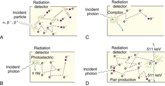
In the case of photons (γ rays, x rays, bremsstrahlung), energy is transferred to the detector primarily in photoelectric, Compton, or pair-production interactions. A portion of the incident photon energy is transferred as kinetic energy to photoelectrons, Compton electrons, or positive-negative electron pairs, respectively, which in turn transfer their kinetic energy to the detector in secondary ionization events (Fig. 10-1B-D). Whether the amplitude of the signal out of the detector reflects the full energy of the incident photon depends on the fate of the remaining energy, which is converted into one or more secondary photons (characteristic x ray, Compton-scattered photon, or annihilation photons). A secondary photon may deposit its energy in the detector by additional interactions*; however, if it escapes from the detector, then the energy deposited in the detector and the amplitude of the signal from the detector do not reflect the full energy of the incident photon. The amplitude of the signal from the detector reflects only the amount of energy deposited in it by the radiation event.
B Spectrometry with Nai(Tl)
Because of its favorable performance-to-cost ratio, a NaI(Tl) scintillator [coupled to a photomultiplier (PM) tube, or in some cases to a photodiode] is the most commonly used detector in nuclear medicine (Chapter 7, Section C). The basic principles of pulse-height spectrometry are illustrated for this detector. Because NaI(Tl) is used almost exclusively for detecting photons (γ rays or x rays, primarily), only photon spectrometry is considered here.
1 The Ideal Pulse-Height Spectrum
Suppose that a monoenergetic γ-ray source is placed in front of a radiation detector. Assume, further, that the energy of the γ rays, Eγ, is less than 1.022 MeV, so that pair-production interactions do not occur. The principle γ-ray interactions with the detector will be by photoelectric absorption and Compton scattering. Most of the photoelectric interactions result in full deposition of the γ-ray energy in the detector (the characteristic x ray usually is also absorbed in the detector). Pulse amplitudes from these events are proportional to Eγ (Fig. 10-2A). With an ideal radiation detector, this would produce a single narrow line in the pulse-height spectrum, called the photopeak, at a location corresponding to the γ-ray energy Eγ (Fig. 10-2B). In Compton scattering, only a part of the γ-ray energy is transferred to the detector, via the Compton recoil electron. If the scattered γ ray also is absorbed in the detector, the event produces a pulse in the photopeak, whereas if the scattered γ ray escapes, the energy deposited in the detector is less than Eγ. According to Equation 6-14, the energy deposited in the detector in a single Compton scattering event ranges from near zero (small-angle scattering event), up to a maximum value Ece, corresponding to the energy of the recoil electron for 180-degree Compton scattering events
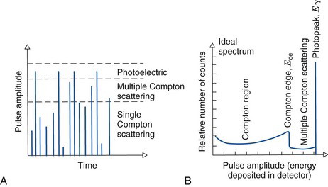
where Eγ and Ece are in MeV. The ideal spectrum therefore includes a distribution of pulse amplitudes ranging from nearly zero amplitude up to some maximum amplitude corresponding to the energy given by Equation 10-1. As shown in Figure 10-2B, this part of the spectrum is called the Compton region. The sharp edge in the spectrum at Ece is called the Compton edge.
2 The Actual Spectrum
In practice, the actual spectrum obtained with a NaI(Tl) spectrometer is quite different from the ideal one shown in Figure 10-2B. For example, Figure 10-3 shows a spectrum obtained from a 137Cs radiation source, which emits 662-keV γ rays and ~30-keV barium x rays. The spectrum was recorded with a multichannel analyzer, 0.01 V per channel, with the amplifier gain adjusted so that 662 keV of energy corresponds to 6.62 V of pulse amplitude. Thus the horizontal axis has been translated from pulse amplitude (~0-8 V) into energy (~0-800 keV).
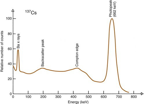
FIGURE 10-3 Actual pulse-height spectrum recorded with a NaI(Tl) detector and 137Cs (662-keV γ rays, ~30 keV Ba x rays). Compare with Figure 10-2B.
The first feature noted is that the spectrum is “smeared out.” The photopeak is not a sharp line, as shown in Figure 10-2B, but a somewhat broadened peak, and the Compton edge is rounded. This is caused by the imperfect energy resolution of the NaI(Tl) detector, discussed in Section B.7.
Another structure that may appear in the spectrum is a backscatter peak. This is caused by detection of γ rays that have been scattered toward the detector after undergoing a 180-degree scattering outside the detector. Certain detector configurations enhance the intensity of the backscatter peak. For example, in the well counter (Chapter 12, Section A), a γ ray may pass through the detector without interaction, then scatter back into the detector from the shielding material surrounding it and be detected.
Equation 10-2 is helpful for identifying backscatter peaks.
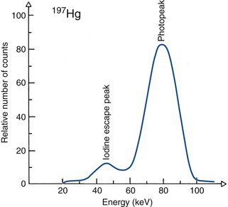
Another structure that may appear is an iodine escape peak. This results from photoelectric absorption interactions with iodine atoms in the NaI(Tl) crystal, followed by escape from the detector of the characteristic iodine K-x ray, which has energy of approximately 30 keV. The iodine escape peak occurs at an energy approximately Eγ – 30 keV; that is, about 30 keV below the photopeak. Iodine escape peaks may be prominent with low-energy γ-ray emitters, for example, 197Hg (Fig. 10-4). Low-energy γ rays are detected by absorption primarily in a thin layer close to the entrance surface of the NaI(Tl) crystal where there is a reasonable probability that the iodine x ray will escape from the detector. With increasing γ-ray energy, the interactions tend to occur deeper within the detector, and there is less likelihood that the x ray will escape. Also, the relative difference between the photopeak and escape peak energies becomes smaller, and it becomes more difficult to distinguish between them.
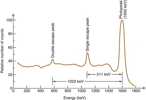
If the γ-ray energy exceeds 1.022 MeV, pair production interactions can occur. The kinetic energy given to the positive-negative electron pair is Eγ – 1.022 MeV (see Chapter 6, Section C.4). In most cases, the entire kinetic energies of both particles are deposited in the detector. When the positron comes to rest, it combines with an electron to create a pair of 511-keV annihilation photons. If both of these photons are absorbed in the detector, the event is recorded in the photopeak. If only one is absorbed, the event is recorded in the single escape peak, at energy Eγ – 511 keV (Fig. 10-5). If both escape, the event is recorded in the double escape peak, at Eγ – 1.022 MeV.
Scattering within or around the radiation source, or object scatter, changes the distribution of radiation energies striking the detector. This is especially important in counting measurements in vivo and in radionuclide imaging because substantial scattering of radiation occurs within the patient. Figure 10-6 shows spectra for 131I with and without scattering material around the source. The general effect of object scatter is to add events in the lower-energy region of the spectrum. It is possible to discriminate against scattered radiation by using a pulse-height analyzer to count only events in the photopeak, as shown in Figure 10-6.
Stay updated, free articles. Join our Telegram channel

Full access? Get Clinical Tree


