Quality Assurance of Image-guided Adaptive Radiation Therapy
Douglas J. Moseley
Jean-Pierre Bissonnette
Michael B. Sharpe
David A. Jaffray
Modern radiation therapy relies heavily on imaging in all stages of patient care, from the diagnosis, staging, simulation, planning, and delivery, to follow-up for treatment outcome assessment. These images come from multiple imaging modalities such as computed tomography (CT), magnetic resonance imaging (MRI), ultrasound, and positron emission tomography (PET). In recent years, radiation treatment has been rapidly stepping into a new era of image-guided radiation therapy (IGRT), where modern imaging techniques are effectively integrated into various steps of the therapeutic process.1 Today, most new medical linear accelerators (linacs) are equipped with a gantry-mounted imaging device,2 providing improved image quality over portal imaging. The improved imaging capabilities allow substantially improved patient localization, more precise quantification of patient rotation and deformation of anatomy,3 and even adaptive replanning of the patient treatment.4
The use and quality assurance (QA) of imaging equipment in radiation oncology are dramatically different from those in diagnostic radiology. In radiology, a patient image is often used in a stand-alone fashion. A set of images, such as CT images from an in-room system, is only a part of the chain process of IGRT. The images must be in the right spatial location and include the proper context.5, 6, 7 To meet the needs of different clinical applications, the images in the form of two-dimensional (2D) radiographic images, 2D fluoroscopic images, or three-dimensional (3D) volumetric images may be required. These images must then be compared to 2D digitally reconstructed radiographs (DRRs) or volumetric reference images from the planning system. Data communication to the linac needs to be established for appropriate intervention, such as the adjustment of the patient position by shifting the treatment couch. All of these add to the complexity of the QA process of a busy radiotherapy clinic. Currently, QA guidelines from professional organizations and advisory bodies (e.g., American Association of Physicists in Medicine [AAPM] task group reports, International Commission on Radiation Units and Measurements [ICRU] reports) are not yet available for many emerging technologies such as in-room image guidance systems and image-guided procedures, yet IGRT is rapidly penetrating into radiation oncology clinics. The purpose of this chapter is to share our experience on IGRT-related issues and lay out the critical pieces for the development of a comprehensive QA program. It is hoped that some insights can be gained on a number of pressing questions in IGRT, such as what image-guided elements need to be included in the routine QA checks and with what frequency to ensure high geometric accuracy and image quality that is adequate to fulfill the task. Reasonable tolerances to achieve high quality given the clinical requirements will be proposed, and expected variation of the equipment will be reported.
ACCEPTANCE AND COMMISSIONING
The introduction of various imaging systems and image guidance procedures in radiotherapy clinics necessitates formal acceptance and commissioning tests of the hardware and processes. Acceptance procedures for medical equipment are usually specified by the manufacturer. The acceptance tests establish that the system or device satisfies performance criteria detailed in the purchase contract. These acceptance tests will often form the basis of the routine QA tests. Device commissioning defines the normal-use criteria as well as the necessary integration with other clinical systems and processes. Meeting the requirements of hardware and the involved processes provides a basis for using the system to manage geometric variations of the patient anatomy and adds confidence for the subsequent clinical applications of the system. The performance criteria specified during commissioning are maintained by a QA procedure constituting a series of periodic tests. Realistic goals and tolerances based on the sensitivity and specificity of the tests need to be set in designing the QA procedure. An analysis of the data collected during acceptance and commissioning is useful in facilitating the process.8 For details on the principles and tasks of acceptance and commissioning, the AAPM reports9, 10, 11, 12 are recommended.
IMAGE-GUIDED PATIENT POSITIONING PROCESS
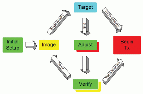
A diagram of the typical IGRT workflow for online image matching is shown in Figure 20.1. After patient setup, an image is formed of the patient in the treatment position. This
image could be an ultrasound slice or volume, a radiographic kilovoltage (kV) image, a portal image, or a volumetric CT. This image is transferred to a targeting system where the online image is compared to a reference image from planning. The desire is to reproduce the conditions that took place during simulation. The targeting can be done manually or by means of an image registration software package.13, 14, 15, 16, 17 The results of the registration will be the displacement of the patient from the planned position. If the displacement is less than a predefined action level, then the treatment proceeds as planned. A typical action level of ±3 mm is used for many treatment sites.18 If the action level is too small, then one needs to intervene and correct the patient position often. If the action level is too large, then there is significant random error in the treatment position. Conversely, more frequent (i.e., daily) imaging leads to higher geometric accuracy.19 Clearly, the action level and the frequency of imaging are contributing factors to the planning target volume (PTV) margins used in treatment planning. The correction of the patient position often involves a 3D translation of the patient using the automated treatment couch. In the presence of rotational error,20 the intervention may involve correction of the patient position in the immobilization device—for example, removal of the thermoplastic mask and adjustment of the neck rest in the case of head and neck cancer. If an adjustment to the patient position is performed manually, several methods are available to monitor the accuracy of the adjustment, including looking at the digital readout of the treatment couch, using an optical tracker on the patient,21 or perhaps acquisition of a verification radiograph or volumetric image. Verification images are useful because they provide a model of the patient in the treatment position and a record of the residual error22, 23, 24, 25; however, verification images incur more time and patient dose.
image could be an ultrasound slice or volume, a radiographic kilovoltage (kV) image, a portal image, or a volumetric CT. This image is transferred to a targeting system where the online image is compared to a reference image from planning. The desire is to reproduce the conditions that took place during simulation. The targeting can be done manually or by means of an image registration software package.13, 14, 15, 16, 17 The results of the registration will be the displacement of the patient from the planned position. If the displacement is less than a predefined action level, then the treatment proceeds as planned. A typical action level of ±3 mm is used for many treatment sites.18 If the action level is too small, then one needs to intervene and correct the patient position often. If the action level is too large, then there is significant random error in the treatment position. Conversely, more frequent (i.e., daily) imaging leads to higher geometric accuracy.19 Clearly, the action level and the frequency of imaging are contributing factors to the planning target volume (PTV) margins used in treatment planning. The correction of the patient position often involves a 3D translation of the patient using the automated treatment couch. In the presence of rotational error,20 the intervention may involve correction of the patient position in the immobilization device—for example, removal of the thermoplastic mask and adjustment of the neck rest in the case of head and neck cancer. If an adjustment to the patient position is performed manually, several methods are available to monitor the accuracy of the adjustment, including looking at the digital readout of the treatment couch, using an optical tracker on the patient,21 or perhaps acquisition of a verification radiograph or volumetric image. Verification images are useful because they provide a model of the patient in the treatment position and a record of the residual error22, 23, 24, 25; however, verification images incur more time and patient dose.
QUALITY ASSURANCE OF IMAGE GUIDANCE DEVICES
As of this writing, no consensual guidelines exist for QA of image guidance systems. Early adopters of this technology have relied on the spirit of established standards, such as the AAPM TG-40 report, vendor literature, and experience acquired at the time of acceptance testing; more rarely, data from quality control (QC) tests have been analyzed to assess the long-term performance of novel equipment. Professional bodies interested in establishing QA and QC guidelines are becoming more interested in rooting device-specific QC to formal analysis of the frequency and severity of the risks or perceived failure modes involved with novel technologies. Many, if not most, undesirable events in radiation therapy have resulted from human performance failures rather than equipment failures.26 Therefore, future guideline QA programs for IGRT would be advised to counsel users to clearly identify the clinical goals to be achieved and align the QA needs to these aims, ensuring effective and useful QA with limited resources or justifying additional resources.
AVAILABLE IN-ROOM IMAGE-GUIDED RADIATION THERAPY DEVICES
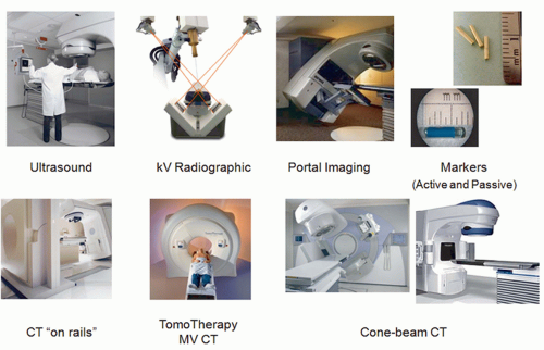
Current technologies for in-room IGRT include many modalities. Figure 20.2 shows a sampling of the methods available. Ultrasound imaging is quick and easy and does not use ionizing radiation.27 However, it is useful only in certain treatment
sites (e.g., prostate, liver, mediastinum) and has limited contrast. Operator dependence of the modality in terms of localization accuracy is another concern.28, 29, 30 Stereographic kV radiographic technologies are relatively inexpensive and can be integrated into the treatment bunker.31, 32, 33 These systems provide a pair of kV radiography systems to facilitate stereoscopic localization. The bony anatomy can be compared with reference DRRs generated by the planning system. Unfortunately, kV radiographs suffer from limited soft tissue contrast. Portal imaging is a mature technology34,35 that captures the exit fluence of the treatment beam to form an image of the beam aperture and the patient anatomy. Portal images can be compared directly to the DRRs from the planning system. Less geometric calibration is required in this approach because the actual treatment field edges of the treatment beam can be used as a geometric reference. Portal images, however, are often difficult to interpret because of the poor contrast of bone and soft tissue at megavoltage (MV) energies.36 To facilitate image guidance with 2D imaging techniques, it is customary to use implanted radiopaque markers as surrogates of a tumor or soft tissue. Passive markers, such as gold seeds, are easily visible in projection images due to their high density and atomic number.37, 38, 39, 40 Active markers include a new technology based on electromagnetic beacons that transmit a signal when excited by an radiofrequency signal from a phased array of antennas.41, 42, 43, 44 The spatial information from these beacons is in real time and accurate. However, it is a single point of reference and provides no information on soft tissue changes.
sites (e.g., prostate, liver, mediastinum) and has limited contrast. Operator dependence of the modality in terms of localization accuracy is another concern.28, 29, 30 Stereographic kV radiographic technologies are relatively inexpensive and can be integrated into the treatment bunker.31, 32, 33 These systems provide a pair of kV radiography systems to facilitate stereoscopic localization. The bony anatomy can be compared with reference DRRs generated by the planning system. Unfortunately, kV radiographs suffer from limited soft tissue contrast. Portal imaging is a mature technology34,35 that captures the exit fluence of the treatment beam to form an image of the beam aperture and the patient anatomy. Portal images can be compared directly to the DRRs from the planning system. Less geometric calibration is required in this approach because the actual treatment field edges of the treatment beam can be used as a geometric reference. Portal images, however, are often difficult to interpret because of the poor contrast of bone and soft tissue at megavoltage (MV) energies.36 To facilitate image guidance with 2D imaging techniques, it is customary to use implanted radiopaque markers as surrogates of a tumor or soft tissue. Passive markers, such as gold seeds, are easily visible in projection images due to their high density and atomic number.37, 38, 39, 40 Active markers include a new technology based on electromagnetic beacons that transmit a signal when excited by an radiofrequency signal from a phased array of antennas.41, 42, 43, 44 The spatial information from these beacons is in real time and accurate. However, it is a single point of reference and provides no information on soft tissue changes.
The remaining image guidance modalities in Figure 20.2 are tomographic or 3D in nature. This feature is crucial for adaptive radiation therapy (ART). The first tomographic system is “CT on rails.”45,46 Here, a diagnostic CT scanner is installed in the same room as the linac and equipped with a couch modified to reproducibly transfer the patient from the imaging position to the treatment position. The benefit of the system is its high image quality and reliable Hounsfield unit (HU) calibration. Notwithstanding the large treatment rooms required for the CT on rails approach, it assumes a fixed relationship between the linac isocenter and the CT images and relies heavily on the mechanical integrity of the two otherwise independent systems. Tomotherapy is a treatment modality that combines imaging and treatment in a single slip ring gantry.47,48 In this system, the patient is imaged and treated sequentially in the same position on the same couch. Imaging with an MV beam, however, is less dose efficient and results in reduced tissue contrast.49,50 The last online image guidance technology in Figure 20.2 is kV cone beam CT (CBCT). A kV x-ray tube and amorphous silicon flat panel detector are mounted on the linac gantry, orthogonal to the treatment beam.51, 52, 53, 54 This allows 2D radiographic or fluoroscopic imaging and 3D volumetric imaging after reconstruction using filtered backprojection55,56 or more advanced methods.57,58 Increased scatter from the cone beam geometry and limited dynamic range of the flat panel detector are two major drawbacks of the modality, which often leads to inferior image quality compared with a diagnostic CT scanner.59, 60, 61
QUALITY ASSURANCE OF GANTRY-MOUNTED KILOVOLTAGE IMAGING SYSTEMS
It is arguable that gantry-mounted imaging systems are one of the most important technical advances for widespread adoption of modern IGRT and developing ART. The QA of such systems is an indispensable part of the overall IGRT/ART process. Several aspects of these systems have been reported,62 including safety,63 geometric accuracy,64, 65, 66 and image quality.67,68 Tests specific to different clinical applications, such as conventional 3D conformal radiation therapy (CRT)/intensity-modulated radiation therapy (IMRT), respiration-gated radiation therapy, and stereotactic radiosurgery, should be designed following the general guidelines from the AAPM.9,10 In general, gantry-mounted imaging systems involve multiple components, and reliable image guidance of the therapeutic process depends on the proper function of each individual part and the system as a whole. Currently, the QA program for onboard imaging systems is still institution dependent, and guidelines for QA and QC of these devices have yet to be enunciated by international bodies such as the AAPM, Institute of Physics and Engineering in Medicine (IPEM), Canadian Organization of Medical Physicists (COMP), and International Atomic Energy Agency (IAEA). Yoo et al.64 described the onboard imaging system QA programs of a few institutions using Varian On-Board Imaging system (Varian Medical Systems, Palo Alto, Calif) and highlighted the issues relevant to the applications of onboard imaging in routine clinical practice. Sharpe et al.65 and Bissonnette et al.60,69,70 reported the geometric and image quality QA experience of the Elekta Synergy system (Elekta, Stockholm, Sweden) at Princess Margaret Hospital (PMH). The following is a brief summary of their findings.
Safety and Functionality of the System
Testing the safety features of gantry-mounted kV imaging systems is typically performed as part of the morning QC procedures and typically involve procedures such as the x-ray warning lights and sound, door interlock, and collision interlocks.71 Other daily tests include the functionality of compute network and control console and warming up the x-ray tube. All of these tests should be performed on a daily basis before any patient is treated.64 This is in accordance with the recommendation of AAPM TG-40.9 A worksheet to facilitate the safety and functionality with more detailed description can be found in Yoo et al.64
Geometric Accuracy
A primary goal of image guidance is to improve the geometric accuracy of radiation therapy by verifying the position of the patient with respect to the treatment beams and to provide an opportunity to correct it immediately prior to the initiation of therapy. To accomplish this, the imaging system itself must be geometrically accurate and stable. There are a number of important mechanical parameters that determine the accuracy of the imaging system, including the coincidence of kV and MV beam isocenters, the positional reproducibility of kV and MV x-ray sources at any gantry angle, and the positional accuracy and orientation of the kV and MV imagers at any gantry angle. In addition, the performance of software tools associated with the clinical use of the system, including planar and volumetric image registration tools,72 should also be examined periodically to ensure the continued geometric accuracy of the system.
The geometric calibration usually relies on using some specially designed phantoms with embedded markers from the linac manufacturers or third-party companies; these tests are
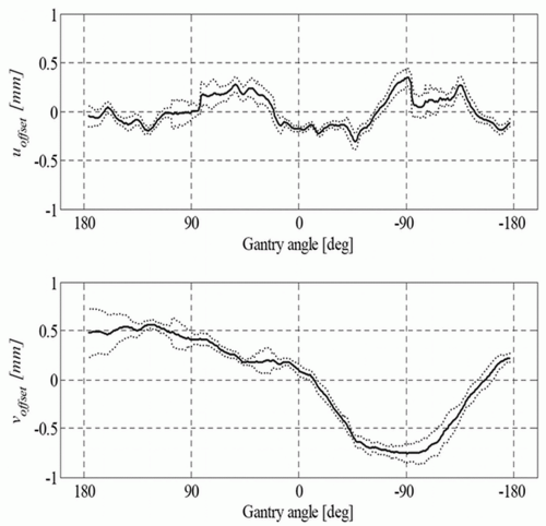
typically variants of the Winston-Lutz test, which was originally developed to ascertain geometric accuracy for brain stereotactic radiosurgery accessories.73 A detailed description of geometric QA of the Varian On-Board Imaging system is given by Yoo et al.64 They also provide simple methods of examining the accuracies of the onboard imaging isocenter and its gantry angle dependence, magnification of the imaging system, run-out during arm vertical travel, and 2D-2D match and couch shift accuracy, along with their clinical experience in using the system. Sharpe et al.65 reported on the mechanical accuracy, precision, and stability of an integrated system (Elekta Synergy) for daily treatment guidance using kV CBCT of soft tissue structures. A technique for geometric calibration of the system was described, with measurements of the accuracy and precision of the entire system for an extended (3-month) period of routine clinical use. An example of reproducibility data of their kV system is presented for the offset and centered panel geometries in Figure 20.3 as the projection of the central axis with respect to the x-ray detector. Sykes et al.74 published a simple measurement of CBCT coincidence with MV isocenter and image sharpness.
typically variants of the Winston-Lutz test, which was originally developed to ascertain geometric accuracy for brain stereotactic radiosurgery accessories.73 A detailed description of geometric QA of the Varian On-Board Imaging system is given by Yoo et al.64 They also provide simple methods of examining the accuracies of the onboard imaging isocenter and its gantry angle dependence, magnification of the imaging system, run-out during arm vertical travel, and 2D-2D match and couch shift accuracy, along with their clinical experience in using the system. Sharpe et al.65 reported on the mechanical accuracy, precision, and stability of an integrated system (Elekta Synergy) for daily treatment guidance using kV CBCT of soft tissue structures. A technique for geometric calibration of the system was described, with measurements of the accuracy and precision of the entire system for an extended (3-month) period of routine clinical use. An example of reproducibility data of their kV system is presented for the offset and centered panel geometries in Figure 20.3 as the projection of the central axis with respect to the x-ray detector. Sykes et al.74 published a simple measurement of CBCT coincidence with MV isocenter and image sharpness.
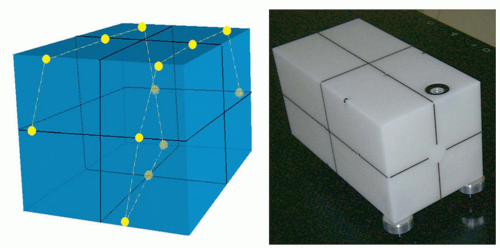
Just as the dosimetric systems of modern accelerators are checked on a daily basis, the geometric systems should be checked just as frequently in this age of image guidance. The geometric calibration procedures described earlier, however, may require too much time to be performed on a daily basis and are difficult to integrate in the daily QC protocols. Anticipating full automation of the QA of onboard imaging systems, the Stanford group has taken a systemic approach and designed a multipurpose imaging phantom with software analysis tool for simultaneous examination of various geometric properties of the integrated kV/MV devices.66 Figure 20.4 shows a sketch of the QA phantom with embedded metallic fiducials. Eight parameters in total are taken into consideration in data analysis. For kV or MV beam, these include the coordinates of x-ray source positions (three variables), center of the imager (three variables), and orientation of the imager (two variables). To obtain the values of the eight parameters for either kV or MV beam with a single projection at an arbitrary gantry angle, multiple metallic fiducials are embedded in the phantom. The software analysis tool extracts the values of the system parameters by comparing the measured and predicted marker locations for a given gantry angle. An accuracy of better than 1 mm was found in detecting any intentionally introduced error in the positions of the x-ray sources or imagers or kV/MV isocenter misalignment. Furthermore, the system was able to reveal any combinational error of the angular and spatial variables at any gantry angle. Alternatively, the group at PMH has been involved in developing a daily QC phantom that integrates several of the classic daily QC checks performed by therapists60,70 and reported an accuracy that is commensurate with that of room lasers. Standard Imaging Inc. (Middleton, Wis) and Modus Medical (London, Ontario, Canada) have licensed these phantoms and made them widely available to the radiation oncology community.
Image Quality
Depending on the specific modality (projection kV x-ray imaging, continuous fluoroscopic imaging, or volumetric CBCT imaging), the image quality tests are different. Issues related to image quality QA in planar imaging include spatial resolution
and contrast resolution; QC tests for these aspects are described in detail in AAPM report no. 74.75 Spatial and contrast resolution tests are typically done using a phantom with embedded line pairs, and the contrast sensitivity and its stability are monitored with the help of embedded objects of known contrasts. Several commercially available phantoms have been used to perform these tasks for gantry-mounted kV imaging systems, including the Leeds phantom.64
and contrast resolution; QC tests for these aspects are described in detail in AAPM report no. 74.75 Spatial and contrast resolution tests are typically done using a phantom with embedded line pairs, and the contrast sensitivity and its stability are monitored with the help of embedded objects of known contrasts. Several commercially available phantoms have been used to perform these tasks for gantry-mounted kV imaging systems, including the Leeds phantom.64
For volumetric imaging, QC test protocols are derived largely from the programs of diagnostic CT systems.11,12,76 Routine examination of image quality is critical not only for us to better see the anatomy, but also for accurate dose calculation based on the volumetric image data.77,78 Volumetric CBCT imaging typically comes with different scanning modes, with different bow-tie filters for different fields of view (FoVs). Each of these scanning protocols should be examined for image quality. Off-the-shelf CT phantoms, such as the popular CatPhan from Phantom Laboratory (Salem, NY) or the AAPM CT Performance Phantom from CIRS (Norfolk, VA), are typically used to perform these QC tests. Bissonnette et al.60,70 have recently reported data from the PMH QA program tracking the image quality performance of 10 volumetric systems over a period of 3 years and used the data for subsequent establishment of evidence-based tolerances for their QA program. Table 20.1 summarizes the image quality components of the QA program currently used at PMH for volumetric imaging system. In the publications by Bissonnette et al.,60,70


Stay updated, free articles. Join our Telegram channel

Full access? Get Clinical Tree


