CHAPTER 1 ![]() RADIOGRAPHY, COMPUTED TOMOGRAPHY, MAGNETIC RESONANCE IMAGING, AND ULTRASONOGRAPHY: PRINCIPLES AND INDICATIONS
RADIOGRAPHY, COMPUTED TOMOGRAPHY, MAGNETIC RESONANCE IMAGING, AND ULTRASONOGRAPHY: PRINCIPLES AND INDICATIONS
WILLIAM E. ERKONEN AND VINCENT A. MAGNOTTA
Computed Radiography (Digital Radiography)
High-Resolution Computed Tomography
Helical or Spiral Computed Tomography
Multislice/Dynamic Computer Tomography
Magnetic Resonance Angiography
Functional Magnetic Resonance Imaging
Functional Cardiac Magnetic Resonance Imaging
Diffusion Weighted Imaging Magnetic Resonance
Magnetic Resonance Spectroscopy
Very few of us take the time to study, let alone enjoy, the physics of the technology that we use in our everyday lives. Almost everybody drives an automobile, for instance, but only a few of us have working knowledge about what goes on under our car hoods. The medical technology that produces imaging studies is often met with a similar reception: we all want to drive the car, so to speak, but we don’t necessarily want to understand the principles underlying the computed tomograms or magnetic resonance images that we study. Yet, a basic understanding of imaging modalities is extremely important, because you will most likely be reviewing images with a radiologist during radiologic consultations throughout your professional life. The results of these consultations will at times profoundly affect your making a clinical decision. Add to this the fact that the interpretation of imaging studies is to a considerable degree dependent on understanding how the images are produced. Here is where our analogy breaks down: One doesn’t necessarily have to be a mechanic to be a skilled driver, but reaching a basic understanding of how imaging studies are produced is a necessary first step to viewing the studies themselves. This chapter is designed to demonstrate the elementary physics of radiologic diagnostic imaging.
Radiographs are the most common imaging consultations requested by clinicians. So let’s set off on the right foot by referring to radiologic images as radiographs, images, or films, but not x-rays. After all, x-rays are electromagnetic waves produced in an x-ray tube. It is acceptable for a layperson to refer to a radiograph as an x-ray, but the knowledgeable clinician and health care worker should avoid the term. Your usage of appropriate terminology demonstrates savoir-faire (the ability to say and do the right thing) to your colleagues and patients.
Whenever possible, radiographs are accomplished in the radiology department. The number of views obtained during a standard or routine study depends on the anatomic site being imaged. The common radiographic views obtained are referred to as posteroanterior (PA), anteroposterior (AP), oblique, and lateral views.
The chest will be used to illustrate these basic radiographic terms, but this terminology applies to almost all anatomic sites. PA indicates that the central x-ray beam travels from posterior to anterior or back to front as it traverses the chest or any other anatomic site (Fig. 1.1). Lateral indicates that the x-ray beam travels through the patient from side to side (Fig. 1.2). When the patient is unable to cooperate for these routine views, a single AP upright or supine view is obtained. AP means that the x-ray beam passes through the chest or other anatomic site from anterior to posterior or front to back (Fig. 1.3). PA and AP radiographs have similar appearances. When the patient cannot tolerate a transfer to the radiology facility, a portable study is obtained, which means that a portable x-ray machine is brought to the patient wherever he or she is located. AP is the standard portable technique with the patient sitting or supine (Fig. 1.4).
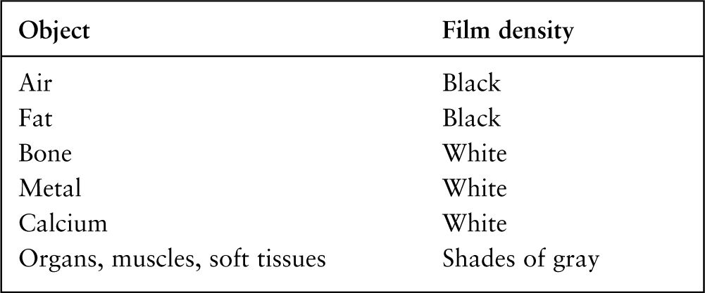
Radiographs have traditionally been described in terms of shades of black, white, and gray. What causes a structure to appear black, white, or gray on a radiograph? Actually, it is the density of the object being imaged that determines how much of the x-ray beam will be absorbed or attenuated (Fig. 1.5). In other words, as the density of an object increases, fewer x-rays pass through it. It is the variable density of structures that results in the four basic radiographic classifications: air (black), fat (black), water (gray), and metal or bone (white; Table 1.1). For example, the lungs primarily consist of low-density air, which absorbs very little of the x-ray beam. Thus, air allows a large amount of the x-ray beam to strike or expose the radiographic film. As a result, air in the lungs will appear black on a radiograph. Similarly, fat has a low density, but its density is slightly greater than that of air. Fat will appear black on a radiograph but slightly less black than do air. High-density objects such as bones, teeth, calcium deposits in tumors, metallic foreign bodies, right and left lead film markers, and intravascularly injected contrast media absorb all or nearly all of the x-ray beam. As a result, the radiographic film receives little or no x-ray exposure, and these dense structures appear white. Muscles, organs (heart, liver, spleen), and other soft tissues appear as shades of gray, and the shades of gray range somewhere between white and black depending on the structure’s density. These shades of gray are referred to as water density.
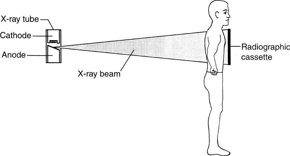
FIGURE 1.1 A posteroanterior chest radiograph. The patient’s chest is pressed against the cassette with hands on the hips. The x-ray beam emanating from the x-ray tube passes through the patient’s chest in a posterior-to-anterior or back-to-front direction. The x-rays that pass completely through the patient eventually strike the radiographic film and screens inside the radiographic cassette.
Radiographic screens are positioned on both sides of the radiographic film inside the light-tight cassette or film holder (Fig. 1.6A). The chemical structure of the screens causes them to emit light flashes or to fluoresce when struck by x-rays (Fig. 1.6B). Actually, it is the fluoresced light from the screens on both sides of the film that accounts for the major exposure of the radiographic film. The direct incident x-rays striking the radiographic film account for a small proportion of the film exposure. The use of screens decreases the amount of radiation required to produce a radiograph, and this in turn decreases the patient’s exposure to radiation. It is important to remember that both radiographic and photographic films respond in a similar manner to light and x-rays.
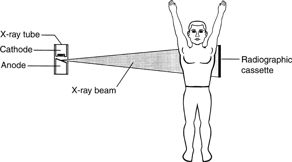
FIGURE 1.2 A lateral chest radiograph. The x-ray beam passes through the patient’s chest from side to side. The x-rays that pass completely through the patient eventually strike the radiographic film and screens. Note that the patient’s arms are positioned as not to project over the chest.
Computed Radiography (Digital Radiography)
In conventional radiography, the radiographic image is recorded on film that goes through chemical processing for development. Computed radiography (CR) or digital radiography (DR) is the process of producing a digital radiographic image. Instead of film, a special phosphor plate is exposed to the x-ray beam. The image information is obtained by scanning the phosphor plate with a laser beam that causes light to be released from the phosphor plate. The intensity of the emitted light depends on the local radiation exposure. This emitted light is intensified by a photomultiplier tube and is subsequently converted into an electron stream. The electron stream is digitized, and the digital data are converted into an image by computer. The resulting image can be viewed on a monitor or transferred to radiographic film. The beauty of this system is that the digital image can be transferred via networks to multiple sites in or out of the hospital, and the digital images are easily stored in a computer or on a server. For example, a digital chest radiograph obtained in an intensive care unit can be transmitted to the radiology department for consultation and interpretation in a matter of minutes. Then the radiologist can send this image via a network back to the intensive care unit or to the referring physician’s office. Of course, this digital information would be stored in a computer (server) for future recall. As this technology improves, it has become more and more important to the routine practice of medicine.
Radiographic contrast media usually refer to the use of intravascular pharmaceuticals to differentiate between normal and abnormal tissues, to define vascular anatomy, and to improve visualization of some organs. These high-density pharmaceuticals in conventional radiology depend upon chemically bound molecules of iodine that cause varying degrees of x-ray absorption. Soft tissues such as muscles, blood vessels, organs, and some diseased tissues often appear similar on a radiograph. Usually, when contrast agents are injected intravascularly to tell the difference between normal and abnormal tissues there is a difference in the uptake of the contrast media in the various tissues. Thus, the more the uptake of contrast media in a tissue, the whiter it appears, and this is called enhancement.

FIGURE 1.3 An anteroposterior chest radiograph. The x-ray beam passes through the patient’s chest in an anterior-to-posterior or front-to-back direction. Note that the patient’s hands are on the hips.
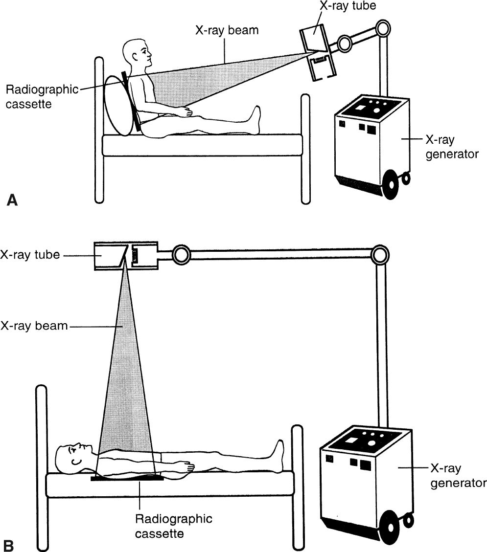
FIGURE 1.4 An anteroposterior portable chest radiograph with the patient either sitting (A) or supine (B). The x-ray beam passes through the patient’s chest in an anterior-to-posterior direction. The x-ray machine has wheels and that allows it to be used wherever needed throughout the hospital.
It is this enhancement or contrast that enables the viewer to detect subtle differences between normal and abnormal soft tissues and between an organ and the surrounding tissues. Also, it beautifully demonstrates arteries and veins.
The use of iodinated high osmolar contrast agents for radiographic studies through the years has led to complications due to this high osmolar load especially in infants and in individuals with compromised renal function. With high osmolar contrast agents, approximately 7% of the people developed reactions consisting of vomiting, pain at the injection site, respiratory symptoms, urticaria, and generalized burning sensation. However, a major advance occurred in the 1990s with the widespread adoption of low osmolar contrast agents (LOCAs) that substantially reduced the risk of osmolar reactions. LOCAs improved the comfort of administration and decreased the frequency of annoying and sometimes life-threatening reactions. LOCAs did not completely eliminate the incidence of serious contrast reaction and nephropathy. If a patient has had a prior reaction, one should consult with one’s radiologist to weigh the benefit versus the risk and possible alternative imaging considered especially in patients with diabetes, vascular disease, or renal dysfunction.
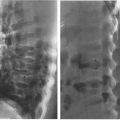
There are many uses for iodinated compounds in radiographic examinations such as in angiography, myelography, arthrography, and computed tomography (CT). Angiography is merely the injection of an iodinated contrast media directly into a vein or artery via a needle and/or catheter (see Chapter 11). Arthrography is the injection of contrast media and/or air into a joint. Air may be used alone or in combination with these compounds to improve contrast. It has been used to image multiple joints such as rotator cuff injuries of the shoulder and to assess meniscus injuries in the knee. Since the advent of CT and magnetic resonance imaging (MRI), the arthrogram has become less important. Myelography is the placement of contrast media in the spinal subarachnoid space, usually via a lumbar puncture. This procedure is useful for diagnosing diseases in and around the spinal canal and cord. Because of the advent of the less invasive CT and MRI modalities, the use of myelogram studies has been decreasing.
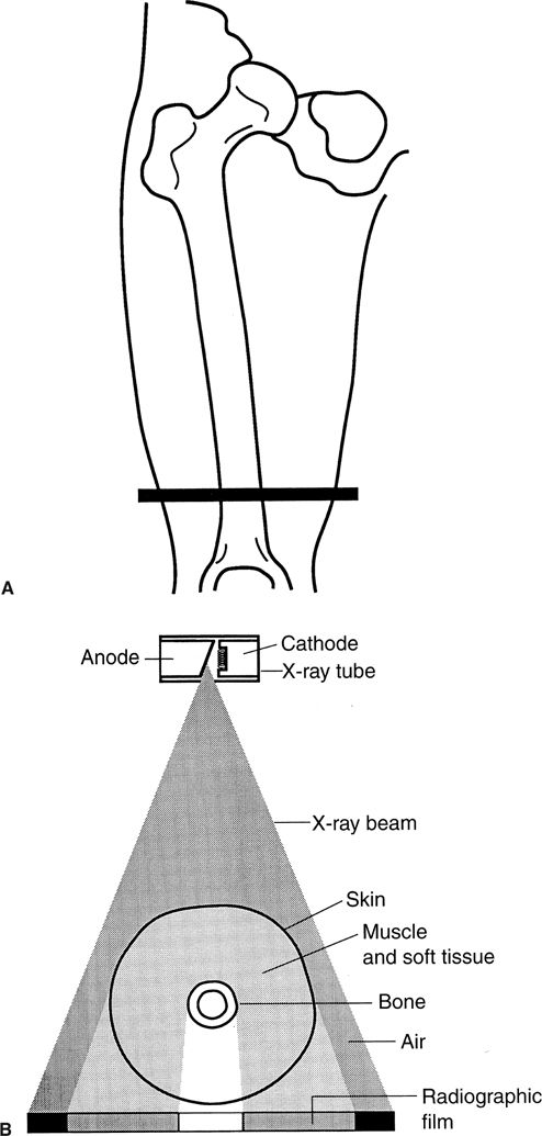
FIGURE 1.5 A: The level in the distal thigh through which the x-ray beam is passing in B. B: Cross section of the distal thigh at the level indicated in A. Notice that when the x-ray beam passes through air, the result is a black area on the radiograph. When the x-ray beam strikes bone, the result is a white area on the radiograph. If the x-ray beam passes through soft tissues, the result is a gray appearance on the film.

BASIC RADIOGRAPH FILM DENSITIES OR APPEARANCES
In the past, orally ingested tablets containing iodinated compounds were used to visualize the gallbladder (oral cholecystogram). These orally administered compounds were removed from the blood by the hepatic cells, then excreted into the biliary tree and concentrated in the gallbladder. This study provided information about gallbladder function and the presence or absence of filling defects such as calculi and tumors. However, this method for imaging the gallbladder is rarely used since ultrasonography imaging became widely available. Ultrasonography is especially useful in acute situations.
The excretory urogram is another examination that is rarely used. This was the method of choice when searching for a wide variety of urinary tract pathologic conditions as well as anatomic and physiologic information. This study uses intravenously injected ionic high and low osmolar iodinated compounds that are excreted by the kidneys. However, this method for imaging the genitourinary system has for the most part been replaced by computer technology.
Another type of contrast media is used for the gastrointestinal (GI) tract. A heavy metal–based compound (usually barium) defines the mucosal pattern very well. To accomplish a GI contrast examination, the barium sulfate suspension is introduced into the GI tract by oral ingestion (upper GI series) or through an intestinal tube (small bowel series) or as an enema (barium enema). When air along with the barium is introduced into the GI tract, the result is called a double-contrast study. Barium studies are safer, better tolerated by patients, and relatively inexpensive compared with the more invasive GI endoscopic studies. Barium studies can be effective in diagnosing a wide variety of GI pathology, as they are quite sensitive and specific.
When the integrity of the GI tract is in question, there exists a potential for catastrophic extravasation of the barium into the mediastinum and peritoneum. In these situations, barium studies are contraindicated and a water-soluble iodinated compound should be used. As a general rule, images produced with water-soluble contrast agents are less informative than barium studies, because the water-soluble agents are less dense than barium and result in poorer contrast.
In MRI standard iodinated contrast agents are of no use. Instead, we use magnetically active compounds such as gadolinium or other metals with unpaired electrons (paramagnetic effects) to enhance imaging certain disease processes. Gadolinium does not produce a magnetic resonance (MR) signal but does cause changes in local magnetic fields by inducing T1 shortening in tissues where it has localized. It is useful for imaging tumors, infections, and acute cerebral vascular accidents. Although the principles of MRI and CT differ, the practical outcomes are similar. They both cause lesion enhancing or in other words a lesion is whiter than the surrounding tissues (Fig. 1.7).
Gadolinium generally has a low risk for reactions and/or nephropathy, but it can cause a severe connective tissue disorder, nephrogenic sclerosing fibrosis (NSF). NSF occasionally occurs in patients who are on dialysis or have a creatinine clearance less than 30 mg/dL. This disease is a very serious complication and is similar to scleroderma. The takeaway lesson on gadolinium is to consult with your radiologist on any patient with known renal failure or a history of NSF before requesting a contrast-enhanced MRI examination.

FIGURE 1.6 A: An open radiographic cassette containing one sheet of radiographic film and two intensifying screens. A radiographic screen is positioned on each side of the film, and the screens emit a light flash (fluoresce) when struck by an x-ray. Also, some x-rays directly strike the radiographic film. This combination of light flashes from the screens and x-rays directly striking the film causes the radiographic film to be exposed. This is similar to photographic film. B: Cross-sectional illustration of a radiographic cassette. Note the lead foil in the back of the cassette that is designed to stop any x-rays that have penetrated the full thickness of the cassette. The curved arrows represent light flashes that are created when x-rays strike the screens.
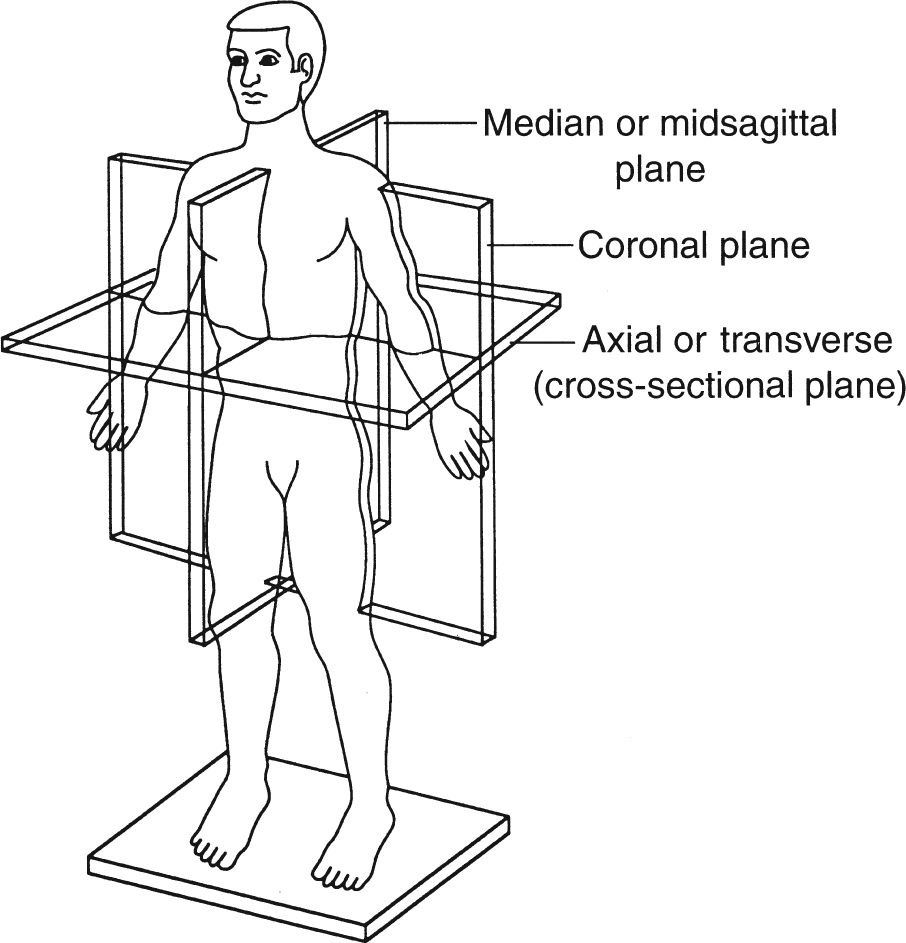
FIGURE 1.7 Sagittal, coronal, and axial anatomic planes.
Computed tomography involves sectional anatomy imaging or anatomy in the sagittal, coronal, and axial (cross-sectional, transverse) planes. These terms, which can be confusing, are clearly illustrated in Fig. 1.7. Sectional anatomy has always been important to physicians and other health care workers, but the newer imaging modalities of computed tomography (CT), magnetic resonance imaging (MRI), and ultrasonography (US) demand an in-depth understanding of anatomy displayed in this manner.
CT, sometimes referred to as computerized axial tomography (CAT) scan technology, was developed in the 1970s. The rock group The Beatles gave a big boost to CT development when it invested a significant amount of money in a business called Electric Musical Instruments Limited (EMI). It was EMI engineers who subsequently developed CT technology. Initially, EMI scanners were used exclusively for brain imaging, but this technology was rapidly extended to the abdomen, thorax, spine, and extremities.
CT imaging is best understood if the anatomic site to be examined is thought of as a loaf of sliced bread; an image of each slice of bread is created without imaging the other slices (Fig. 1.8). This is in contradistinction to a radiograph, which captures the whole loaf of bread as in a photograph.
The external appearance of a typical CT unit or machine is illustrated in Fig. 1.9. CT images are produced by a combination of x-rays, computers, and detectors. A computer-controlled couch transfers the patient in short increments through the opening in the scanner housing. In the standard CT unit, the x-ray tube located in the housing (gantry) rotates around the patient, and each anatomic slice to be imaged is exposed to a pencil-thin x-ray beam (Fig. 1.10). Each image or slice requires only a few seconds; therefore, breath holding is usually not an issue. The thickness of these axial images or slices can be varied from 1 to 10 mm depending on the indications for the study. For example, in the abdomen and lungs we commonly use a 10-mm slice thickness because the structures are large. A slice thickness of only a few millimeters is used to image small structures like those found in the middle and inner ear. An average CT study takes approximately 10 to 20 minutes depending on the circumstances.
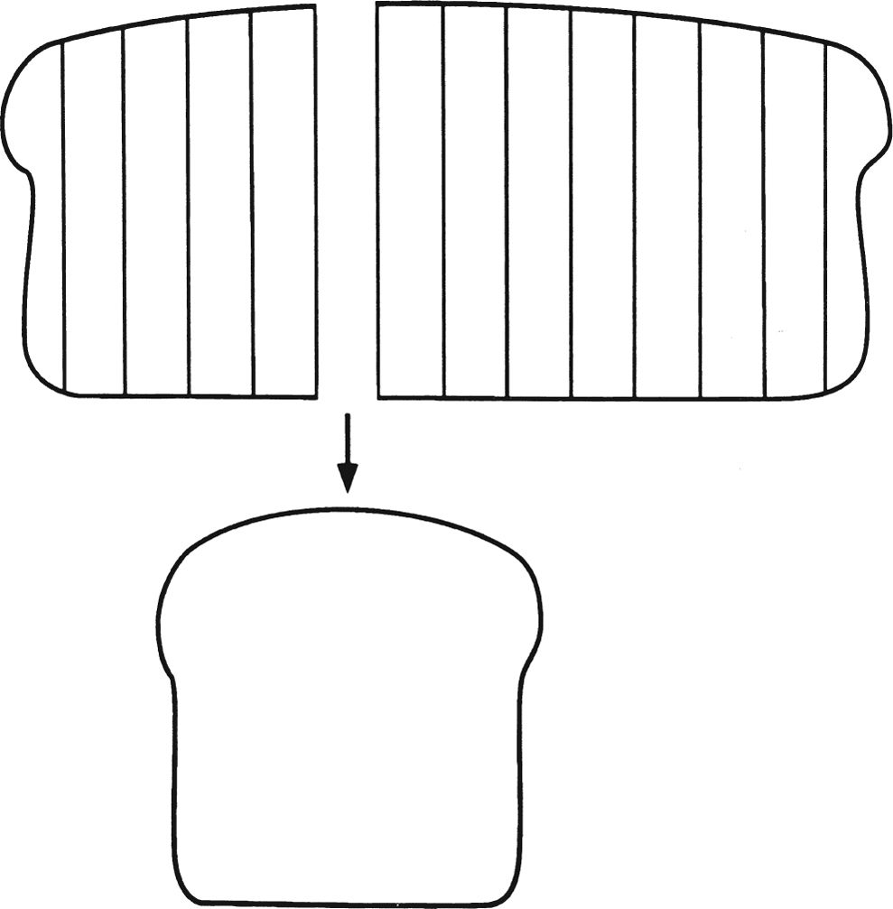
FIGURE 1.8 Illustration of how CT technology creates an image of a single slice of bread from a loaf of sliced bread without imaging the other slices.
As in a radiograph, the amount of the x-ray beam that passes through each slice or section of the patient will be inversely proportional to the density of the traversed tissues. The x-rays that pass completely through the patient eventually strike detectors (not film), and the detectors subsequently convert these incident x-rays to an electron stream. This electron stream is digitized or converted to numbers referred to as CT units or Hounsfield units; then computer software converts these numbers to corresponding shades of black, white, and gray. A dense structure, such as bone, will absorb most of the x-ray beam and allow only a small amount of x-rays to strike the detectors. The result is a white density on the image. On the other hand, air will absorb little of the x-ray beam, allowing a large number of x-rays to strike the detectors. The result is a black density on the image. Soft tissue structures appear gray on the image.
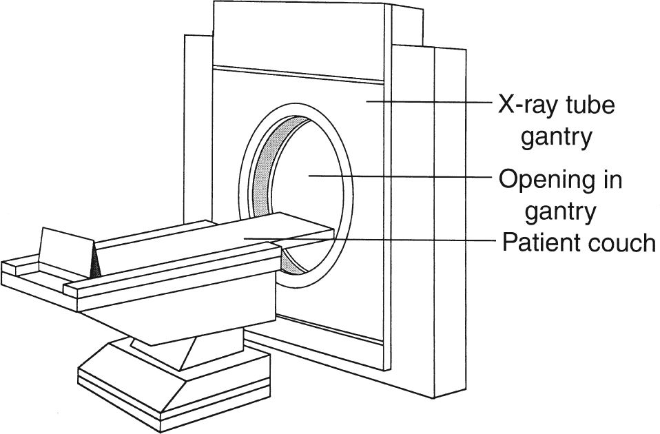
FIGURE 1.9 A standard CT scanner or machine. The patient couch or cradle is fed through the opening in the x-ray tube gantry or housing, and the anatomic part to be imaged is centered in this opening. The x-ray tube is located inside the gantry and moves around the patient to create an image.
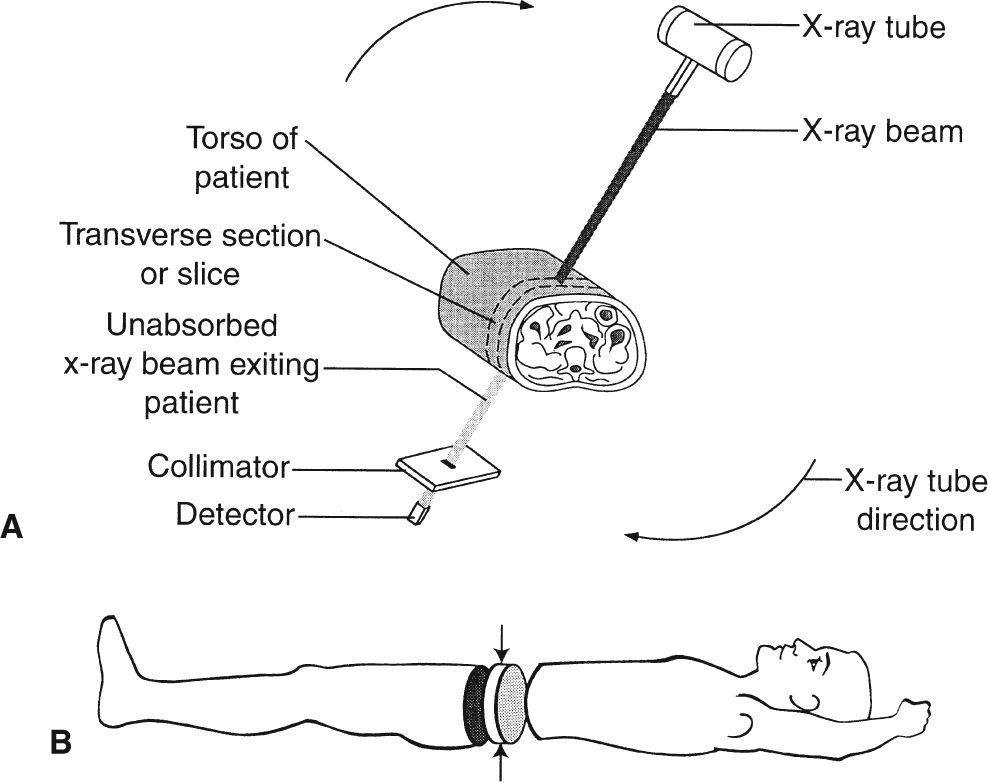
FIGURE 1.10 A: Illustration of how the x-ray tube circles the patient’s abdomen to produce an image (slice) as shown in B. B: Demonstration of how a CT scan creates a thin-slice axial image of the abdomen (arrows) without imaging the remainder of the abdomen.
This CT digital information can be displayed on a video monitor, stored on magnetic tape, transmitted across computer networks, or printed on radiographic film via a format camera.
Because CT technology uses x-rays, the image densities of the anatomic structures being examined are the same on both CT images and radiographs. In other words, air appears black on both a CT image and a radiograph and bone appears white on both modalities. One major difference between a radiograph and a CT image is that a radiograph displays the entire anatomic structure, whereas a CT image allows us to visualize slices of a structure. Another major difference is that in radiography the x-rays that pass through an object are recorded on film, whereas in CT the x-rays are recorded by devices called detectors and converted to digital data.

Related posts:


Stay updated, free articles. Join our Telegram channel

Full access? Get Clinical Tree


