Fig. 13.1
Nine different k-space sampling strategies. (a) Single k-space line per shot with a Cartesian trajectory. (b) Single-shot EPI sampling trajectory. (c) Multi-shot, interleaved EPI trajectory. (d) Single-shot RARE sampling trajectory (with dashed line showing the effect of refocusing pulses). (e) Multi-shot, interleaved RARE trajectory. (f) Radial trajectory with a single line or “ray” per shot. (g) Propeller trajectory with rotated segments and RARE-type acquisition. (h) Single-shot spiral trajectory. (i) Multi-shot, interleaved spiral trajectory
In Fig. 13.1a, each excitation (each TR) produces one line in k-space. Only by making TR very short is imaging time short enough for real-time applications using this sampling scheme (see later discussion on short TR sequences). For example, if the TR is reduced to around 3 ms, then the acquisition time to acquire 256 lines can be under 1 s and short enough for real-time imaging. A fluoroscopic, sliding-window type of reconstruction is sometimes used whereby images are reconstructed each time one or several new k-space lines are acquired [10]. While this can give a temporally smooth real-time looking result, it should be noted that this does not actually increase the fundamental temporal resolution.
Multiple-Echo Sequences
Sequences where multiple k-space lines are sampled in a single TR are especially suitable for real-time imaging. The single-shot variants of these multiple-echo sequences are of great interest because they can acquire data for a single plane very rapidly and are minimally affected by motion. Echo planar imaging (EPI) [11] and RARE (also known as turbo spin echo or fast spin echo) sequences [12] are the two main varieties of multi-echo sequences.
Echo Planar Imaging (EPI)
In the EPI sequence [11], multiple gradient echoes are formed by swinging the gradient back and forth with successive positive and negative gradient pulses. The entire 2D k-space can be sampled in a single TR period as shown schematically in Fig. 13.1b. The k-space lines are sampled in the left-to-right direction during application of a positive x-gradient (frequency encoding). Lines are sampled in the opposite direction (right-to-left) during application of a negative x-gradient. Small y-gradient blips applied in the phase-encoding direction (y) are used to move the k-space sampling from line to line.
Single-shot EPI is very fast, and a variety of different contrasts are possible, such as T2* weighting for thermal mapping [13–15]. However, single-shot EPI is not always the best choice of sequence in iMRI because of the image distortions that are caused by local magnetic field inhomogeneity, unless extra efforts are made to correct such distortions [16]. Field inhomogeneities cause localized off resonance and additional phase evolution of the acquired signal over the echo-train length. As a result, k-space values acquired at different echo times acquire different phase offsets [17]. Then, when images are reconstructed, this phase variation results in a local shift or distortion in the image, often around interventional devices that disturb the field. This distortion in single-shot EPI can be mitigated to some extent by shortening the echo-train length with reduced field-of-view imaging [18] or parallel imaging [19].
Multi-shot EPI sequences [20] can also be used to shorten the echo train. Such sequences have been applied, for example, in real-time temperature mapping [21–23]. Figure 13.1c shows a schematic of the trajectory for a multi-shot EPI sampling scheme for which the full 16 lines are acquired in 4 shots of 4 lines each, reducing the echo-train length by a factor of 4.
RARE, Fast Spin Echo or Turbo Spin Echo
In the RARE sequence, one line of k-space is sampled in each of the intervals between successive refocusing pulses. As with EPI, it is possible with RARE to obtain an entire plane of k-space data in one TR period [24], and therefore, RARE is also suitable for real-time interactive imaging [25, 26]. Note from the schematic of the trajectory in Fig. 13.1d that the sampling direction is left to right for all lines due to the effect of the refocusing pulse (represented by the dashed lines in Fig. 13.1d) that reverses the effect of the frequency-encoding gradient and returns the k-space sampling location to the left side of k-space.
Even though the echo trains are much longer in RARE than with EPI, distortion is less of a problem because the magnetization is refocused between the acquisition of successive k-space phase lines, and significant phase evolution over the echo-train duration is eliminated. Single-shot RARE has been shown to be a desirable sequence for real-time iMRI especially due to its excellent T2 contrast [27, 28].
One of the main disadvantages with single-shot RARE sequences is that due to the use of many refocusing pulses, the minimum time between shots (TR) is much longer than with EPI because of SAR limits and a longer time for T1 recovery is needed. Additionally, the T2 decay over the duration of the echo train can result in significant blurring. The echo-train length can be reduced with the use of reduced FOV imaging [26, 29–31] or parallel imaging [19, 32].
A multi-shot RARE is also possible, and Fig. 13.1e shows the schematic whereby the 16 lines are acquired in 4 shots of 4 lines each. Though these sequences are much faster than single spin-echo sequences and are used routinely in diagnostic imaging [33, 34], the acquisition times are usually at least in the tens of seconds and, therefore, still rather slow for true real-time imaging. Because of their superb tissue contrast, however, they are often used in iMRI for periodic evaluation during a procedure.
Non-cartesian κ-Space Sampling
Radial κ-Space Sampling
In all of the sequences discussed above, k-space sampling trajectories have been on a rectilinear or Cartesian grid. With appropriate gradient design, non-Cartesian trajectories are possible. Figure 13.1f shows the trajectory for a radial sequence. Like the example in Fig. 13.1a, 16 TRs are taken to fill k-space although, in the radial case, the individual k-space lines sampled are now at different angles.
The most obvious difference between radial and Cartesian sampling is the variable density of sampling lines in the radial case. An advantage is that over-sampling the center results in higher SNR. Effective motion correction schemes can be devised as each acquired line can be seen as a navigator for motion detection [35]. As with Cartesian sampling, full k-space acquisitions based on single-line per TR sampling are too slow for real-time applications unless significant under-sampling is used [36, 37] as it is, for example, in 3D stereoscopic imaging [38]. As with Cartesian sampling, a continuous fluoroscopic-type reconstruction can also be employed [39].
Figure 13.1g illustrates the trajectory for a method referred to as “Propeller” [40]. In the example shown, a multi-shot spin-echo sequence is used to sample four partial segments of k-space lines. On each new shot, the segment is reoriented at a different angle to the K x -axis. An advantage of this approach is that, in any single shot, a low-resolution image can be reconstructed and used to correct for in-plane motion [41]. The multi-spin-echo version of Propeller is actually somewhat slower than regular multi-shot RARE. However, it lends itself well to a sliding-window (or fluoroscopic) reconstruction, and because of the capability for self-navigated motion correction, it might still be considered for some iMRI applications for which rapid updates are less critical. Some acceleration can also be achieved by reducing the number of rotated segments [42]. High-speed versions of Propeller are possible with the use of EPI trajectories [43].
Spiral κ-Space Sampling
Another popular strategy for sampling k-space in a single TR is to follow a spiral trajectory as shown schematically in Fig. 13.1h. Spiral trajectories tend to be very time-efficient in gradient usage, and images can be acquired at a rate suitable for real-time iMRI [44]. Real-time calibration is necessary to deal with timing errors, Eddy currents, etc. [45], and fast reconstruction including re-gridding is necessary for application in iMRI. As shown schematically in Fig. 13.1i, multi-shot versions of spiral sampling with interleaved spiral acquisition are also possible [44, 46] and could be used when high resolution is desired [47] or when one wants to minimize distortions that result from the use of long-duration spirals.
Partial κ-Space Sampling Methods
An effective approach to speeding up acquisitions for real-time imaging is to reduce the sampling in k-space. Three basic approaches are shown schematically in Fig. 13.2.
Fig. 13.2
Partial k-space sampling schemes. (a) Full k-space sampling – high spatial resolution. (b) Keyhole sampling – low spatial resolution. (c) Reduced FOV – reduced k-space density. (d) Partial/half Fourier sampling (with optional additional lines shown in gray)
Keyhole Imaging
The simplest way to reduce the acquisition is to acquire only the lines around the center of k-space as shown schematically in Fig. 13.2b (compared to full k-space sampling shown in Fig. 13.2a). A full image can be acquired in this case; however, spatial resolution in the y-direction would be reduced by one half. This approach has been used in a dynamic imaging method known as “keyhole” [48, 49] whereby one begins with full k-space dataset but acquires only the center section dynamically, for example, to update the position of an interventional device such as a biopsy needle [50].
Reduced Field-of-View (FOV) Imaging
Another approach to reduce k-space sampling is to reduce the density of sampled lines as shown schematically in Fig. 13.2c. However, because the FOV in the y-direction is inversely proportional to the k-space increment between sampled K y lines, this would lead to wraparound (aliasing) if the object being imaged is too big for the reduced FOV. Wraparound can be avoided if the RF excitation is designed in such a way as to excite a reduced range of spins within the FOV [30, 31, 51, 52].
Reduced FOV imaging makes particular sense in cases where the object being tracked, such as biopsy needle or catheter, is relatively small [29], or one is only interested in the focus of heating in a thermal therapy procedure [53]. An advantage with the reduced FOV approach compared to keyhole imaging is that spatial resolution is not sacrificed. There is, however, a penalty in terms of SNR reduction by a factor equal to the square root of the FOV reduction. Reduced FOV approaches have also been developed and applied in iMRI for radial and spiral sampling approaches [54].
Partial Fourier Imaging
Another option is to sample only one side of k-space as shown in Fig. 13.2d [55]. This approach takes advantage of the principle that if an object is real, its Fourier transform is conjugate symmetric and half of the sampled values in k-space are redundant, i.e., could be computed from values in the other half of k-space. Even if the real-valued assumption is not completely valid, if some of the lines from the second half of k-space are sampled (gray lines in Fig. 13.2d), very good results can be obtained with a homodyne reconstruction as long as the phase variations in the distribution are relatively smooth spatially [56]. In dynamic imaging, artifacts caused by imperfect reconstruction from partial Fourier data can be mitigated to a considerable degree by special application of the UNFOLD technique [57].
Constrained Reconstruction and Compressed Sensing
Other methods have been developed for reconstructing high-resolution images from under-sampled k-space data that attempt to take advantage of prior assumptions about the data. In constrained reconstruction approaches, prior information such as a baseline high-resolution image is used to “constrain” the reconstruction of the dynamically updated information [58]. A method referred to as HIPR, which is applied in MR angiography (MRA), claims an enormous boost in temporal resolution approaching the time taken for a single projection (e.g., one TR) [59]. It is suitable only when signal distribution is sparse such as in MRA.
A relatively new approach developed for reconstructing images from under-sampled k-space data is compressed sensing (CS) [60, 61]. Like HIPR, CS makes use of sparsity; however, it is less restrictive because signal only needs to be sparse in some transform domain (e.g., wavelet domain). In CS, k-space is sampled according to a pseudorandom pattern so that artifacts created by a direct reconstruction are incoherent. A nonlinear reconstruction algorithm is applied that tries to impose both sparsity in the transform domain as well as data consistency. CS looks very promising as a method for accelerating imaging to rates suitable for real-time iMRI [62, 63]; however, reconstruction times are quite long and require special hardware such as graphics processing units [64–67] to achieve the minimum latency needed for real-time imaging.
Temporal Sampling Approaches
There are also temporal sampling approaches that take advantage of redundancy in dynamic imaging [68, 69]. In the UNFOLD method, the wraparound caused by under-sampling in k-space can be resolved by acquiring the temporal data in a somewhat different way (modulating phase) from time frame to time frame and applying special temporal filters [70] to remove the aliased component. Special UNFOLD filters suitable for real-time iMRI have been developed [71, 72]. This idea of exploiting redundancy in the temporal domain has also been used to improve parallel imaging reconstructions through better sensitivity mapping [71] and for suppressing reconstruction artifacts [57]. Very high degrees of acceleration have been obtained using methods such as kt-SENSE [73]; however, these methods may not be adaptable for real-time imaging.
Parallel Imaging
Parallel imaging methods are applicable whenever receiver array coils and multiple-channel receiver systems are available. With parallel imaging, acceleration of image acquisition by a factor of two (through subsampling in k-space) with standard array coils is common, and with special coils and/or methodologies, acceleration of five or more is possible.
A number of methods such as SMASH [74], SENSE [75], SPACERIP [76], and GRAPPA [77, 78] have been introduced. Although there are important differences in these approaches, they all make use of information in the spatially variable sensitivity profiles of receive coil arrays. A very simple case would be an idealized 2-coil-2-receiver system where one coil “saw” only the right side of the FOV and the other coil saw only the left side, and the signals from each coil were fed into two independent receivers. Compared to the required full FOV setting for a single-coil system, the size of the FOV in the 2-coil-2-receiver system could be set to one half the full size without any wraparound because each coil would see only half the FOV. In this simple example, compared to the single-coil-single-receiver system, imaging time would be cut in half (and SNR reduced by a factor of the square root of 2).
In practice, the individual coils do not exclusively see their own parts of the FOV; a significant overlap in the sensitivity of the coils is usually present. However, even with overlap, as long as one has knowledge about the coil sensitivities, images can be reconstructed from the multiple receiver datasets. Parallel imaging methods differ in their approaches for subsampling k-space, in the algorithms they use for reconstructing images from the partially sampled data, and in how they use and acquire the sensitivity information. In some cases, it has been shown that hybrid methods combining features of multiple different approaches can give results [68, 79] that are better than what is possible with the individual approaches alone.
Acceleration rates beyond four seem reasonable with standard array coils. However, it is important to appreciate that an SNR penalty comes with these acceleration rates that are at least equal to the square root of the acceleration rate. And because of the spatial overlap in sensitivities between coils, which leads to solving non-orthogonal systems, the SNR penalty is actually higher. Additionally, for real-time applications in iMRI, one must also consider the added computational overhead although, with special hardware such as GPUs, this is becoming less of a concern [64, 67].
Short TR, Steady-State Pulse Sequences
Short TR, steady-state pulse sequences have become workhorses for iMRI [80] because they are fast enough for real-time imaging, offer high SNR, and can provide a range of contrasts. The distinguishing feature of all steady-state sequences is that signal survives between RF excitations and is “reused” in future TR intervals. In these sequences, the TR is normally quite short, perhaps as little as between 2 and 3 ms. A sequence like FLASH (Fast Low-Angle Shot) [81] will also have a short TR; however, the signal does not survive between excitations as efforts are made to “spoil” it [82]. Spoiled FLASH is still used in iMRI for a number of real-time applications [83–86].
The signal dynamics in a steady-state pulse sequence can become quite complicated [87, 88], but the basic idea is simple once one accepts that any RF pulse will have multiple effects on the signal. When we first learn the principles of MRI, we are taught that RF pulses either “excite” the magnetization from the longitudinal axis into the transverse plane or “refocus” the transverse magnetization. This view, however, is incomplete and only suitable to fully explain signal dynamics in MRI when a sequence consists of a single excitation pulse (usually 90°) followed by a single refocusing pulse (180°) and when no transverse magnetization survives into the next TR period. The important difference in considering steady-state sequences is to consider the multiple pathways for the signal on each RF excitation.
Unbalanced Steady State
If between RF pulses the signal from the transverse magnetization feels some net dephasing effects of imaging gradients applied in that TR interval, the sequence is unbalanced and the signal pathways become separated by how much dephasing they experience in each interval [87, 88]. Since the imaging gradients are under our control, however, signal pathways can be selected via different gradient designs to give different contrast behavior. Unbalanced steady-state sequences have been applied for real-time imaging in a number of iMRI applications [80, 89–93].
Figure 13.3 shows a steady-state pulse sequence design with the RF and three possible read-gradient designs. In the gradient design at the top, a negative gradient pulse is followed by a positive gradient of twice the area. A gradient-refocused echo will be formed during the playout of the positive gradient pulse in the first TR interval; thus, this looks like a standard gradient-echo sequence. Each new pulse leads to formation of a gradient echo from excited longitudinal magnetization. Although there are spin-echo signal components created by later RF pulses, the basic characteristic of this sequence (often referred to as FISP) is gradient-echo-like.
Fig. 13.3
Partial schematic of short TR, steady-state sequences showing RF pulses and different read-gradient designs. In the unbalanced-I design, transverse magnetization generated from an RF pulse is refocused in the TR interval immediately after the pulse. In the unbalanced-II design, an echo is not formed from transverse magnetization generated by a pulse in the TR interval immediately after the pulse. Spin echoes and stimulated echoes are formed in later intervals. In the balanced design, because there is no net dephasing from imaging gradients in a TR interval, all magnetization pathways combine
In the middle of the three gradient designs, the order of the positive and negative gradient lobes is reversed. Now, no echo can be formed in the first TR interval from the new transverse magnetization generated by the first RF pulse. However, the second RF pulse creates a negative signal pathway that will be refocused with the positive gradient in the second TR interval, leading to a spin-echo formation (and a stimulated echo will be generated in the next interval). In this sequence (referred to as PSIF or CS-FAST), signal components come from refocused magnetization, either spin echo or stimulated echo. It is possible to obtain both the FISP and PSIF components with a special dual-echo sequence, and this has been proposed for use in monitoring thermal therapies [93].
Balanced Steady State
The plot at the bottom of Fig. 13.3 shows the gradient design of a balanced steady-state sequence (trueFISP or FIESTA) [94, 95]. It is called “balanced” because the net dephasing in each TR interval due to imaging gradients is zero. As a result, in this kind of sequence, all magnetization pathways are combined and will be sampled when an echo is formed. This sequence tends to be very high in SNR because all signal pathways are sampled; however, the contrast, which is T2/T1 weighted [94], is more complicated than in the unbalanced sequences because of the combination of these pathways.
Combining pathways can also have a negative effect when phase evolution due to magnetic field inhomogeneity (e.g., from susceptibility) varies significantly between pathways. In this case, there is destructive interference from the combination resulting in the well-known band artifact. With very short TR, however, balanced steady-state sequences become practical and have widespread use in iMRI for applications such as tracking of catheters [62, 84, 96–103], and other interventional devices [27, 80, 104], although artifact problems still remain in areas of severe susceptibility. Though not usual, variants of the balanced steady-state sequence have also been used for real-time temperature mapping [105–107].
Techniques to Deal with Motion
A moving subject is vulnerable to motion artifact because displacement of the subject during a series of echo signal acquisitions causes phase inconsistencies among those signals that lead to artifacts in the reconstructed image (ghosting, blurring, etc.). The issue is especially serious when large displacement occurs in a relatively short period compared to imaging time, e.g., cardiac and respiratory motion. Despite the progress of fast imaging techniques as we reviewed in the previous section, those fast imaging techniques often do not satisfy the requirement for specific image contrast. To address the issue of motion artifact, researchers have been developing a number of MR imaging techniques to prevent or correct phase inconsistencies in echo signals due to motion of the subject that is usually incorporated into the existing imaging sequences. The advantage of using those techniques to prevent or correct the phase inconsistency with existing imaging sequences over using whole new fast imaging sequences is that they are less likely to impact the image contrast. Most of those techniques focus on the detection of “intra-image” motion, i.e., motion during the acquisition of data for a single image dataset. Special approaches, as discussed below, are required to compensate for such intra-image motion.
Gating
A widely used technique is respiratory gating [108–110] that has its underlying assumption that respiratory motion is repetitive and reproducible as a function of respiratory phase; thus, there is a window period in respiratory cycles when the target organ shows the same state in each cycle (Fig. 13.4). Therefore, one can avoid the phase inconsistencies by monitoring the respiratory phase and accepting echo signals only during the window period when the respiratory phase is within the predefined range. Since echo signals used for image reconstruction are selected based on the respiratory phase, accurate respiratory monitoring is crucial in the gating technique. The most common approach is to use an external device such as belt-like device that detects the change of patient’s girth due to the subject’s breathing [108–110] (Fig. 13.5). This approach has been shown to give good results [110]. For interventions performed under general anesthesia with controlled ventilation, the spirometric signal from an MR-compatible anesthetic machine is an ideal choice for respiratory monitoring [111] because controlled breathing provides better phase consistency compared to respiratory gating in a natural free-breathing condition.
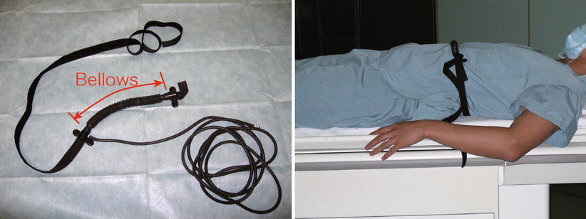
Fig. 13.4
In respiratory gating, MR signal acquired only while respiratory signal is in the predefined window near the end-expiratory phase of breathing, where motion of the subject is relatively small
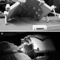
Fig. 13.5
An example of MRI-compatible belt-like device for detecting the subject’s respiratory phase for gating. The device shown in this figure has a bellows that changes its volume while stretching due to the change of the patient’s girth due to breathing. The bellows is filled with air and connected to a remote sensor via an air hose
Another common approach to respiratory monitoring is the navigator echo technique [112–114] whereby an MR echo (navigator echo) specialized for detecting the intra-image motion of the subject is acquired along with the imaging data. The advantage of respiratory monitoring using navigator echoes is that it directly detects the displacement of the internal anatomical structures without using any additional sensors; thus, the method can be implemented by making only a change to the pulse sequence in MRI systems. Detailed principles of motion correction will be discussed in the next section. In the context of iMRI, gating techniques are particularly important for intraoperative MR thermometry in MRI-guided hyperthermia or RF/microwave ablation therapy because MR thermometry based on the proton resonance frequency (PRF) method relies on accurate measurement of phase shift in the MR signals. Intraoperative MR thermometry has been incorporated with gating methods including spirometry signal from an anesthesia machine [111] and navigator echoes [115, 116].
Motion Correction
One drawback of gating is that a large number of echo signals acquired outside of the defined window period are discarded resulting in a prolonged total imaging time. Instead of discarding echo signals with inconsistent phases, Ehman and Felmlee proposed an approach to correct the inconsistency based on the shift of the subject [112]. The key challenge in motion correction is to estimate the intra-image displacement at each echo signal acquisition – something that cannot be estimated from the reconstructed image. The contribution of Ehman and Felmlee was a method to estimate the displacement of the subject from a single navigator echo. By interleaving acquisitions of navigator echoes and imaging echoes, intra-image displacement of the subject can be quantified and motion compensated. The simplest form of navigator echo was a 1D projection navigator (a single readout without phase encoding). In k-space, the sampling trajectory of this navigator echo is represented as a line along the frequency-encoding direction. The sampled echo is converted to the projection of the signal distribution of the excited volume onto the frequency-encoding axis by Fourier transformation. The translation of the subject along the frequency-encoding axis can be detected as a shift of the projection. More recently, researchers have extended the method to more than 1 degree of freedom (DOF) by introducing more sophisticated navigator echoes, e.g., orbital navigator echo [113] and spherical navigator echo [114], that sample along a circle or sphere in k-space, allowing one to detect 3 DOF and 6 DOF motion of the subject, respectively. Like the gating techniques, applications of the motion correction techniques can be found in the field of intraoperative MR thermometry for MRI-guided hyperthermia or laser/RF/microwave ablation therapy [115, 117, 118].
Motion Tracking and 4D Imaging for Adaptive Image Guidance
Other researchers have investigated MR-based motion tracking and 4-dimensional (4D) MRI (i.e., using a time series of 3D MR images) as tools for adaptive treatment guidance and planning. Adaptive guidance and planning based on 4D images have been discussed in the field of radiotherapy of lung cancer, whereby an irradiated area is precisely planned based on 4D CT prior to radiotherapy taking account of organ motion and adaptively controlled by the real-time feedback, e.g., fluoroscopy to minimize the margin of the irradiated area [119–121]. Blackall et al. proposed using dynamic 3D MRI to plan radiotherapy for lung cancer [122] taking advantage of fast imaging sequences and parallel imaging technologies, which allow the rapid acquisition of 3D images. They achieved an acquisition time of 330 ms/image by using fast field echo with echo planar imaging (FFE-EPI). The limitation of their approach is that the image quality of the dynamic 3D images was insufficient to show structures in detail, requiring image registration of dynamic 3D images and high-quality breath-hold 3D images. To address the issue of insufficient quality in the dynamic 3D imaging, several techniques to acquire 4D MRI based on gating have been proposed in the literature. Siebenthal et al. implemented 4D imaging using internal respiratory gating [123]. They used fast 2D imaging (180–190 ms/frame) both to detect the respiratory phase and to acquire multi-slice images and then reconstructed a 4D image by post-processing. Jhooti et al. proposed a use of multiple gating windows for automatic selection of optimal gating windows [124, 125], but only a few volumes were acquired at the peaks of the histogram of motion in the latter work [125]. Tokuda et al. developed an adaptive method to acquire 4D MRI [126] whereby phase encoding for MR imaging echo acquisition was adaptively adjusted by monitoring the respiratory phase and feeding it back to the imaging sequence during a scan.
Localization of Instruments
Localization of interventional instruments, such as needles and catheters, is crucial for interactive operation in MRI-guided interventions so that the clinician can place these instruments accurately at the focal lesion. Furthermore, the imaging plane must be adjusted so as to be able to visualize the tip of the instrument and capture the progress of the treatment. However, localization of the instrument is challenging due to several reasons: conventional instruments are either invisible on MR images or create a serious susceptibility artifact; frame rate of real-time MRI is usually not sufficient to track the instrument for interactive operation; and real-time images are usually 2D and not capable of localizing the instrument in the 3D space in real time. To address those issues, researchers have investigated techniques to track instruments either using “active,” “passive,” or other MR-based tracking approach or introducing additional tracking sensor devices.
Passive Tracking
Passive tracking attempts to localize instruments, e.g., catheters and needles, or markers by detecting them in MR images. The desired localization is usually achieved by using specially designed instruments that are visible on MR images [99, 127–130] or by using imaging techniques that can highlight instruments placed in the patient’s body [29, 131–136]. The advantage of passive tracking over active tracking is its simplicity; it does not require any electrically conductive device, making it easier to fabricate an instrument as well as reducing the risk of local heating.
One of the focused areas of work in passive tracking is the development of catheters visible on MR images. To guide a catheter by MR images, researchers have developed passive tracking catheters that create susceptibility artifact by using ferromagnetic materials [127–129], or positive contrast on MR images by filling the tip with contrast agent [137–139]. There have also been studies of passive catheter tracking by nuclear magnetic resonance of other nuclides such as 19F [130] or 13C [99].
Another focused area of work is needle tracking during MRI-guided biopsy. Since standard stainless steel needles create susceptibility artifact larger than the actual needle leading to inaccuracy in needle localization, the challenge in MR-based needle tracking is to rapidly and clearly visualize the needles on the MR images. This requires both the development of MRI-compatible needles and the optimization of pulse sequences. MRI-compatible needles that have less magnetic susceptibility and thus smaller needle artifact have been developed since the mid-1980s [131–134]. For MRI pulse sequences, several groups have proposed rapid spin-echo sequence based on the projection reconstruction technique [135] and single-shot fast spin echo (SSFSE or HASTE) with reduced FOV (or “local look” technique) [29, 136] specifically for needle localization (as discussed in the previous section). The idea behind the combination of single-shot spin-echo imaging with reduced FOV technique is that the MRI sequence based on spin echo is resistant to local field inhomogeneity, and by limiting the FOV, one can obtain a high-resolution spin-echo image with reasonable imaging time (~1 frame/s [29]) for real-time application. MRI also has the potential to create a positive contrast of needle or other instrument by highlighting the magnetic field perturbation due to the presence of an object in the field that shifts the local frequency off resonance [140, 141].
Passive markers are also used for localization and placement of needles. Oliveira et al. proposed a needle-holding device integrated with MR-visible markers for MRI-guided transrectal prostate biopsy [86]. DiMaio et al. proposed a unique Z-shaped fiducial frame for passive tracking that can be attached to interventional instruments [142].
Active Tracking
Active tracking employs small RF coils embedded in the interventional instruments to pick up the signals only from the spins near the coils after the nonselective RF pulse excitations. The position of those coils is encoded by applying a readout magnetic field gradient along one of the primary axes. The position is then decoded by applying Fourier transformation to the acquired echo signal. Fourier transformation of such echo signal provides a projection of MR signal distribution in the excited volume onto the readout axis, thus allowing for the localization of the coil in the readout direction as a signal peak. The principle of active tracking was initially proposed in the mid-1980s [143] and has been investigated by several groups for catheter and needle tracking [144–148]. The approach is capable of tracking multiple coils simultaneously to visualize the trajectory of the catheter rather than just the tip position [168]. The advantage of active tracking over passive tracking is that the temporal resolution of active tracking is much greater. Unlike the passive tracking approach, the active tracking approach does not require reconstruction of an entire MR image to enable the detection of intra-image motion. In addition, active tracking is not limited by selection of the 2D imaging plane. A potential drawback of active tracking is the safety concern raised by the use of an electrically conductive device that is introduced into the patient’s body. The long cable used to connect the RF coil embedded in the instrument may act as a dipole antenna that picks up RF energy during the scan, leading to local heating [149, 150]. There have been several studies to address the issue of heating by using coaxial chokes [151], wireless detuning with optical system [152, 153], or sensors based on the Faraday effect [154].
Other MR-Based Tracking Approaches
Some researchers have proposed alternative approaches that combine the features of passive and active tracking. Steiner et al. proposed a tracking coil with an internal signal source embedded in the tip of an instrument [155]. Because the approach does not rely on signals from the tissue around the coil, it allows for the localization of the instrument even in tissues with poor MR signals, such as in the lung. A similar concept was used in instrument tracking based on electron spin resonance (ESR) [156]. In ESR instrument tracking, substances that contain unpaired paramagnetic electrons, e.g., radical-ion TCNQ, are used as a signal source. The advantage of the ESR-based tracking over the NMR-based tracking is the smaller size of signal source and shorter relaxation time that lead to faster tracking. Ehnholm et al. prototyped a needle with an ESR-based tracking probe and successfully demonstrated its capability.
Related posts:

Stay updated, free articles. Join our Telegram channel

Full access? Get Clinical Tree


