Detectors
Effective Atomic no (Z)
Density (g/cm3)
Scintillation decay time (ns)
Photon yield (per keV)
NaI(T1)
51
3.67
250
38
BGO
74
7.13
300
6
BaF2
54
4.89
0.6
2
GSO
59
6.71
50
10
LSO
66
7.40
40
29
YSO
34
4.53
70
46
CsI(T1)
54
4.51
1000
52
LYSO
65
7.2
50
25
YAP
39
5.4
27
18
LaBr3
47
5.3
16
61
CZT
50
5.8
–
–
NaI (Tl) Detector
Pure sodium iodide produces very little scintillation after interaction with γ-radiations at room temperature. However, if it is doped with a trace amount (0.1–0.4 %) of thallium as an activator, NaI(Tl) becomes quite efficient in producing light photons after γ-radiations interact with it. NaI(Tl) molecules are excited or ionized by interaction with γ-rays or x-rays, and the high-energy states return to ground states by emitting light photons. Approximately 20–30 light photons are produced per 1 keV of energy .
The choice of NaI(Tl) crystals for γ-ray detection is primarily due to the high density (3.67 g/cm3) of the detector and the high atomic number of iodine (Z = 53), compared to organic scintillators. However, NaI(Tl) crystals are hygroscopic and fragile, and must be handled with care. Room temperature should not be changed abruptly, because such changes in temperature can cause cracks in the crystal.
Bismuth Germanate Detector
The bismuth germinate (BGO) detector has a higher density and effective atomic number and so higher attenuation coefficient (hence, higher stopping power) for 511 keV photons than NaI(Tl). But it has a slightly longer scintillation decay time (300 ns) compared to NaI(Tl) (250 ns) and its light output is relatively small causing poor energy resolution. However, energy resolution has minimal effect on the spatial resolution of PET , which is mainly determined by the size of the detectors . Moreover, BGO crystals are not hygroscopic. Because of these factors, BGO is preferred to NaI(Tl) for most positron emission tomography (PET) cameras.
Barium Fluoride Detector
Barium fluoride (BaF2) is an inorganic crystal that has a very fast decay time (0.8 ns) and offers a suitable detector for time-of flight PET. The photon yield of this crystal is relatively small and it is slightly hygroscopic.
Lutetium Oxyorthosilicate Detector
Lutetium oxyorthosilicate (LSO) doped with cerium is another solid detector that is used for scintillation counting in PET imaging. LSO has a shorter scintillation decay time (40 ns) than BGO that favors the use of a narrow pulse window to cut down random coincidences in PET . Also, its higher light output gives a better energy resolution than BGO . These detectors have high efficiency for photon detection and can be fabricated in the size of a few millimeters . Many commercial manufacturers use LSO detectors in place of BGO detectors in clinical PET scanners and in micro-PET scanners for scanning small animals.
Gadolinium Oxyorthosilicate Detector
Gadolinium oxyorthosilicate (GSO) is a detector that can be used for coincidence counting in PET imaging. Even though it has lower light output and stopping power than LSO, its better energy resolution has prompted some commercial manufacturers to use it in PET scanners. GSO crystals are fragile and great care is warranted in their fabrication.
Yttrium Oxyorthosilicate Detector
Yttrium oxyorthosilicate (YSO) is an inorganic crystal similar to LSO introduced for scintillation counting. The scintillation decay time of YSO is 70 ns and it gives high light output. A combination detector of YSO/LSO has been reported for potential use in simultaneous single photon and coincidence imaging. YSO detects low-energy photons and LSO detects 511 keV photons, and the two pulses are readily separated by pulse shape discriminators.
Yittrium Aluminum Perovskite Detector
Yttrium aluminum perovskite (YAP) doped with cerium (Ce) is a low Z detector with high light output and shorter scintillation decay time of 27 µs, almost ten times shorter than NaI(Tl). It is neither fragile nor hygroscopic and can stand variations in temperatures. Although it has been used for some x-ray imaging, its use in SPECT and PET cameras has been limited.
Lutetium Yttrium Oxyorthosilicate Detector
Lutetium yttrium oxyorthosilicate (LYSO) is a useful detector because of its higher density and atomic number providing greater stopping power. The detection efficiency of the detector is similar to that of the LSO detector and it has been used in PET scanners by some manufacturers.
Lanthanum Bromide Detector
Lanthanum bromide (LaBr3) has high density and atomic number and reasonably shorter scintillation decay time (16 ns) . Its high photon yield and hence its superior energy resolution make it a good candidate for detectors in medical imaging. Like NaI(Tl), it is, however, hygroscopic and needs to be housed in an enclosure.
Solid-State Detectors
Germanium and Silicon Detectors
Solid-state or semiconductor detectors are made of germanium or silicon elements commonly doped with lithium . These detectors are designated as Ge(Li) or Si(Li) detectors, of which the former are commonly used for high-energy γ-ray detection and the latter for α-particle and low-energy radiation detection. Currently, high purity germanium (HPGe) alone without lithium is commonly used. The basic principle of operation of these detectors involves ionization of the semiconductor atoms, as in gas detectors. When radiation interacts with a semiconductor, ionization occurs with the transfer of an electron from the valence band to the conduction band and concomitant creation of a positively charged hole in the valence bond. When an electric field is applied, the electron-hole pairs migrate to the respective electrodes and produce voltage pulses. The pulses are then amplified and counted. The size of the pulse is proportional to the radiation energy absorbed in the detector, but does not depend on the type of radiation. Note that there is no light production and therefore no photomultiplier tube is needed.
Because semiconductors are much denser than gases, they are more efficient for x- and γ-ray detection than gas detectors. Also in semiconductor detectors , each ionization requires only about 3 eV compared to 35 eV in gas detectors. Thus, almost ten times more ions are produced in semiconductor detectors than in gas detectors for a given γ-ray energy, thus yielding a better spectral resolution of γ-ray photons of closer energies. Fabrication of Ge(Li) and Si(Li) detectors is quite time-consuming and expensive. The size of the detectors is also small, which prevents their use in gamma cameras.
Thermal noise at room temperature introduces a high background that can obscure the sample counts, but is reduced at low temperature. Therefore, these detectors are operated at low temperature usually employing liquid nitrogen (− 196°C or 77°K). A disadvantage of these detectors is that liquid nitrogen evaporates over time and needs to be replenished periodically, typically weekly. Nowadays HPGe detectors can be kept at room temperature when not used, and cooled when used for counting by means of helium-based cryoelectric and freon-based coolers.
Semiconductor detectors are most useful in differentiating photon energies because of the high-energy resolution, particularly in detecting radionuclidic contamination. These detectors are not in common use in nuclear medicine.
Cadmium–Zinc–Tellurium Detector
Cadmium–Zinc–Tellurium (CZT) detectors are another type of semiconductor made of Cd, Zn, and Te metals, and provide very high efficiency for γ-ray detection because of their high atomic numbers . For reasons of high detection efficiency, these detectors can be made as small as 2 mm thick and 2 mm diameter with almost 100 % efficiency for 100 keV photons. The energy resolution of these detectors is very good (~6%)for a wide range of γ-ray energies . These detectors are operated at room temperature. The electronics used are similar to those of other scintillation detectors. Different types of handheld probes have been devised for various purposes. One probe, called the Neoprobe 1000, is used for the detection of metastatic sites containing radioactivity (e.g., 1251-labeled monoclonal antibody) during surgery for their removal by incision. Also this detector has been used in gamma cameras manufactured by Spectrum Dynamics and GE Healthcare.
Cesium Iodide (CsI(Tl)) Detector
The CsI(Tl) detector has higher density and hence greater stopping power than the NaI(Tl) detector and also yields more light photons per keV. But its scintillation decay time is very long (1000 ns) resulting in longer dead time for the counting system. The crystal is weakly hygroscopic and does not require hermetic sealing. Unlike NaI(Tl), it can withstand a wide variation in temperature.
Solid Scintillation Counters
A basic solid scintillation counter consists of a scintillation detector, a PM tube, a preamplifier, a linear amplifier , a PHA, and a recording device (Fig. 8.1). The most commonly used scintillation detector in γ-ray counting is NaI(Tl), although BGO and LSO are commonly used in PET, discussed later. Each of these components is described in detail next.
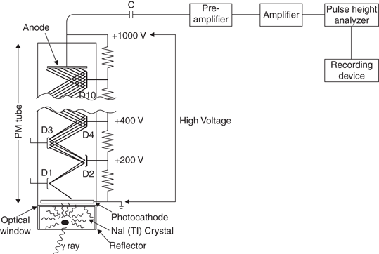

Fig. 8.1
A basic scintillation counter consisting of a NaI(Tl) detector, a photomultiplier (PM) tube, a preamplifier, a linear amplifier, a pulse-height analyzer, and a recording device. The high voltage applied to the PM tube is typically 1000 V
NaI(Tl) Detector
The NaI(Tl) detectors are made of various sizes for different types of equipment. Circular or cylindrical crystals vary from 3.8 to 50 cm in diameter and 0.63–23 cm in thickness. Rectangular crystals of approximate dimension of 45 ´ 60 cm are also available. In thyroid probes and well counters , smaller and thicker crystals are used, whereas larger and thinner crystals are employed in scintillation cameras .
Photomultiplier Tube
A PM tube consists of a light-sensitive photocathode at one end, a series (usually ten) of metallic electrodes known as dynodes in the middle, and an anode at the other end—all enclosed in a vacuum glass tube (see Fig. 8.1). The photocathode is usually an alloy of cesium and antimony or other bialkali metal that releases electrons after absorption of light photons. The PM tube is fixed on to the NaI(Tl) crystal with the photocathode facing the crystal by a special optical grease or connected to the crystal using light pipes.
A high voltage of ~1000 V is applied between the photocathode and the anode of the PM tube in steps of 50–150 V between dynodes (see Fig. 8.1). Dynodes are coated with materials such as Cs and Sb that are good for secondary emission of electrons. When light photons from the NaI(Tl) crystal strike the photocathode, approximately one to three photoelectrons are produced from the photocathode per 7–10 light photons. Each of these photoelectrons is accelerated to the first dynode and emits two to four electrons upon impingement. The accelerated electrons strike the successive dynodes, and more electrons are emitted. The process of multiplication continues until the last dynode is reached, where a pulse of 105–108 electrons is produced. The pulse is then attracted to the anode and finally delivered to the preamplifier. The amplitude of the pulse is proportional to the number of light photons received by the photocathode and in turn to the energy of the γ-ray photon absorbed in the detector. The applied voltage must be very stable, because slight changes in dynode voltage cause a great variation in electron multiplication factor.
Preamplifier
The pulse from the PM tube is small in amplitude and is initially amplified by a preamplifier. The preamplifier adjusts the voltage of the pulse (pulse shaping) and matches impedance level between the detector and the subsequent circuits so that the pulse is appropriately processed by the system.
Linear Amplifier
A linear amplifier amplifies further the signal from the preamplifier and delivers it to the pulse height analyzer for analysis of its amplitude. The amplification of the pulse is given by the amplifier gain expressed as the ratio of the amplitude of the outgoing pulse to that of the initial pulse from the PM tube. The amplifier gains are given in the range of 1–1000 by gain control knobs provided on the amplifier. The output pulses normally have amplitudes of up to 10 V.
Pulse-Height Analyzer
γ-rays of different energies can arise from a source of the same or different radionuclides or due to scattering of γ-rays in the source and the detector. Thus, in counting a radioactive source, the pulses coming out of the amplifier may differ in magnitude. A PHA is a device that selects for counting only those pulses falling within preselected voltage intervals or “channels” and rejects all others (see Fig. 8.1). Pulses corresponding to γ-ray energies of interest are selected by energy discriminator knobs, known as the lower level and upper level, or the baseline and window, provided on the PHA, and are ultimately delivered to the recording devices such as scalers, computers, films, and so on.
There are two modes of counting using PHAs: differential and integral . In differential counting, only pulses of preselected energies are counted by appropriate selection of lower and upper level knobs (discriminators) or the baseline and window . In scintillation cameras, however, differential counting is achieved by a peak voltage knob and a percent window knob. The peak voltage knob sets the energy of the desired γ-ray, and the percent window knob sets the window width in percentage of the γ-ray energy, which is normally placed symmetrically on each side of the peak voltage.
In integral counting, γ-rays of all energies or all γ-rays of energies above a certain energy are counted by setting the appropriate lower level or baseline and bypassing the upper level or window mechanism.
A PHA normally selects only one range of pulses corresponding to only one γ-ray energy by means of differential counting. Such a PHA is called a single-channel analyzer (SCA) . A multichannel analyzer (MCA) is a device that can simultaneously sort pulses into many predetermined voltage ranges or channels, corresponding to different photon energies . By using an MCA, one obtains a simultaneous spectrum of different γ-ray energies from a radioactive source.
Display or Storage
Pulses processed by the PHA can be displayed on a cathode ray tube (CRT) or can be counted for a preset count or time by a scaler-timer device. A rate meter can be used to display the pulses in terms of counts per minute (cpm) or counts per second (cps). In scintillation cameras, pulses can be used to form the image on a CRT and polaroid or x-ray films. These pulses can also be stored in a computer or on a magnetic tape or laser disc for processing later. Nowadays, computer monitor and storage are the mainstay for display and storage of data in nuclear medicine.
Gamma-Ray Spectrometry
Pulses are generated by the PM tube and associated electronics after the γ-ray energy is absorbed in the NaI(Tl) detector. Because γ-rays interact with the NaI(Tl) detector by photoelectric, Compton, and pair production mechanisms, and also because various scattered radiations from outside the detector may interact with the detector, a distribution of pulse heights will be obtained depicting a spectrum of γ-ray energies. Such a γ-ray spectrum may result from a single γ-ray or from many γ-rays in a sample . Different features of this spectrum are discussed here.
Photopeak
In an ideal situation, if the γ-ray photon energy is absorbed by the photoelectric mechanism and each γ-ray photon yields a pulse of the same height, then each γ-ray would be seen as a line on the γ-ray spectrum (Fig. 8.2a) . In reality, the photopeak is broader, which is due to various statistical variations in the process of forming the pulses. These random fluctuations arise from the following conditions:
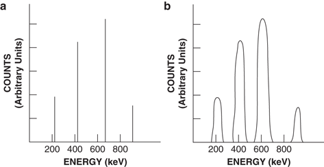

Fig. 8.2
γ-ray spectra. a An ideal spectrum would represent the different γ-rays as lines. b An actual spectrum showing the spread of the photopeak that is due to statistical fluctuations in the pulse formation
1.
Because 20–30 light photons are produced for every keV of γ-ray energy absorbed, there is a statistical variation in the number of light photons produced by the absorption of a given γ-ray energy in the detector. Also, statistically all light photons produced may not strike the photocathode.
2.
As already stated, 7–10 light photons are required to release 1–3 photoelectrons from the photocathode. Therefore, the number of photoelectrons that one γ-ray will produce may vary from one event to another.
3.
The number of electrons released from the successive dynodes by impingement of each electron from the previous dynode varies from 2 to 4, and therefore pulse heights from the PM tube will vary from one γ-ray to the next of the same energy.
All of the preceding statistical fluctuations in generating a pulse cause a spread in the photopeak (see Fig. 8.2b). A typical spectrum of the 662-keV γ-ray of 137Cs is shown in Fig. 8.3.
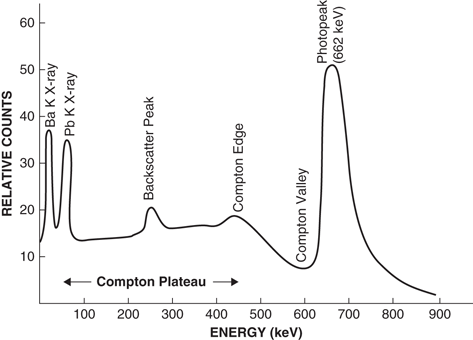

Fig. 8.3
A typical spectrum of the 662-keV γ-ray of 137Cs illustrating the photopeak, Compton plateau, Compton edge, Compton valley, backscatter, characteristic lead K x-ray, and barium K x-ray peaks
Compton Valley, Edge, and Plateau
When γ-rays interact with the NaI(Tl) detector via Compton scattering and scattered photons escape from the detector, the Compton electrons result in pulse heights that are smaller than that of the photopeak. The Compton electrons, however, can have variable energies from zero to E max , where E max is the kinetic energy of those electrons that are produced by the 180° Compton backscattering of the γ-ray photons in the detector. At relatively high photon energy, E max is given by the photon energy minus 256 keV (Eq. 6.3). Thus, the γ-ray spectrum will show a continuum of pulses corresponding to Compton electron energies between zero and E max . The peak at E max is called the Compton edge , and the portion of the spectrum below the Compton edge down to about zero energy is called the Compton plateau (see Fig. 8.3). The portion of the spectrum between the photopeak and the Compton edge is called the Compton valley , which results from multiple Compton scattering of a γ-ray in the detector yielding a narrow range of pulses in this region.
Stay updated, free articles. Join our Telegram channel

Full access? Get Clinical Tree


