Secondary Magnetic Resonance Imaging Magnets
Objectives
At the completion of this chapter, the student should be able to do the following:
• Identify shim coils and their purpose.
• Understand the shape and positioning of the three sets of gradient coils.
• Describe quadrature detection and its relevance to magnetic resonance (MR) signal detection.
• Discuss the difference between homogeneous and inhomogeneous radiofrequency (RF) probes.
• List the advantages and disadvantages of surface coil and phased array coil imaging.
Key Terms
On the one hand, magnetic resonance imaging (MRI) requires a uniform static magnetic field (B0) to produce a strong, coherent free induction decay (FID) signal. On the other hand, precisely fashioned gradient magnetic fields are required to deliberately spoil the homogeneity in order to provide spatial location information. The gradient magnetic fields are produced by secondary electromagnetic coils that are usually of the resistive type but can be superconducting.
In addition to the gradient coils that produce the gradient magnetic fields, there are shim coils in some high-field MRI systems. There also is an integrated radiofrequency (RF) coil, which is often referred to as “the body coil.” These secondary coils are positioned inside the bore of the cylinder of the gantry.
Indeed, the gradient coils and shim coils are designed to produce precise magnetic fields, which are superimposed on the primary static magnetic field. The body coil most typically is used to transmit RF energy into the patient, but sometimes may be used to receive the induced MRI signal from the patient too.
Shim Coils
Shimming is the process of making the B0 field uniform throughout the imaging volume. The shimmed volume will determine the volume of the static magnetic field suitable for imaging. The shimming process often involves placing steel bars in the magnet at precise positions in trays located along the inside of the magnet bore. Primary shimming of a magnet is usually perfomed at the factory. The MRI system installation engineer will likely do some fine tuning of the magnet’s shim at the site.
Room temperature coils may also be used to improve the B0 field unformity within the patient for particular procedures that require high magnetic field homogeneity. On systems operating at 1.5 T and below, this procedure only requires a DC offset of the current applied to the gradient coil. At 3 T and higher, separate coils are installed that adjust the higher functional orders of the magnet field. These are the shim coils.
 Magnetic field uniformity is termed homogeneity.
The Parts per Million Scale
The specification of magnetic field homogeneity as parts per million (ppm) is borrowed from nuclear magnetic resonance (NMR) spectroscopy. This allows field homogeneity to be expressed independent of field strength. If a 1.0 T magnet were perfectly homogeneous throughout the imaging volume, it would be stated as ±0 ppm. A homogeneity of ±1 ppm is a variation of ±1 µT throughout the imaging volume of a 1.0 T magnet (1 T = 106 µT). A homogeneity of ±5 ppm in a 1.5 T magnet would be ±7.5 µT.
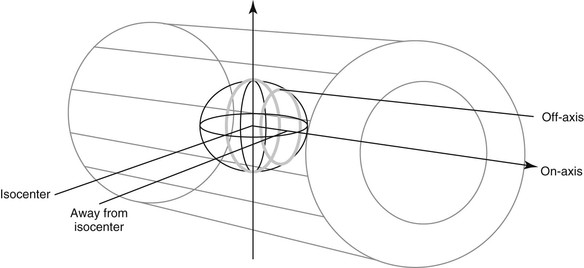
 Magnetic field homogeneity is specified as the ppm over a specific spherical volume.
Acceptable homogeneity over a 20 cm spherical volume is approximately 20 ppm with permanent magnets but only 1 ppm with superconducting magnets. The spherical volume is usually specified in terms of the diameter of the spherical volume or DSV.
For a 1.5 T field, the proton Larmor frequency is 63 MHz. If field homogeneity of 10 ppm is achieved, the resonance frequency in the shimmed volume will be 63 MHz ± 630 Hz. For a 0.5 T system operating the same way, 10 ppm homogeneity means the proton Larmor frequency is 21 MHz ± 210 Hz.
Shimming the Magnet
The imaging volume in an MRI system generally consists of a cylinder with a diameter of approximately 60 cm and a length along the Z-axis of 50 to 70 cm. A conventional six-coil superconducting magnet will normally produce a magnetic field with homogeneity of approximately ±5 ppm.
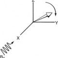
When determining the B0 magnetic field homogeneity, the installation engineer will typically use a small probe containing a tiny sample of water to measure the resonance frequency and map the magnetic field. A special jig is used to position the small probe at precise locations within the magnet bore.
Once the measurements are performed, then the homogeneity can be modified by placing steel shims in trays located in the bore of the magnet. The magnetic field can be mapped again and this procedure is repeated until satisfactory magnetic field homogeneity is achieved. Figure 11-1 is a diagram that shows the geometry of this measurement.
Once the magnet has been properly shimmed, the procedure is not repeated unless operating techniques or the site environment changes greatly. With high-speed functional imaging techniques and chemical shift–sensitive fat suppression, better B0 homogeneity is required.
Current superconducting magnets are designed and manufactured according to precise specifications. Gross shimming is performed at the factory with the installation engineer completing only minor corrections. What used to take up to 2 weeks now requires just hours.
 Shimming is the process of making the B0 field homogeneous.
An actively shielded magnet incorporates superconducting shim coils in the cryostat with the primary magnet. This seems to be the most effective shim design of all. Field homogeneity of less than ±1 ppm is attainable with superconducting shim coils.
During installation of an MRI system the magnet is brought up to field, and the homogeneity of the B0 field is optimized with the bore clear of gradients or RF coils. For superconducting electromagnets, this homogeneity may be accomplished with the aid of superconducting coils within the cryostat itself.
Room temperature or resistive shim coils are configured to alter the magnetic field on the basis of spherical coordinates. The “first order” terms are the familiar x, y, and z directions. Second order terms include x2, y2, z2, xy, yz, and so on. These “higher order” terms are required only for extremely high-homogeneity applications, such as spectroscopy.
The most common method for application-specific shimming in conventional MRI systems is to offset the baseline currents of the X, Y, and Z gradient coils. This method can usually achieve the desired degree of field homogeneity with the standard hardware.
Shimming using only the gradient coils produces adequate results partly due to the superior homogeneity of modern superconducting magnets. However, for higher field systems that are used for spectroscopy studies, in which a higher degree of homogeneity is required, an independent set of room temperature shim coils may be necessary.
During prescan calibration, additional shimming may be required because of patient size, shape, and magnetic susceptibility. The patient may reduce the field homogeneity due to the differences in magnetic susceptibility among different tissues. For SE imaging, such prescan shimming often is not required. However, at high B0 with fast imaging and especially for magnetic resonance (MR) spectroscopy, prescan shimming may be necessary. Such prescan shimming is computer controlled and requires little technologist time.
Gradient Coils
If room temperature shim coils are used, another cylinder is positioned inside the cylinder on which the shim coils are wound. The gradient coils are positioned on this second cylinder. If room temperature shims are not used, the gradient coils are just inside the bore of the primary magnet, near the walls of the housing.
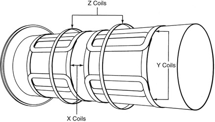
There are three sets of gradient coils, one each for the X, Y, and Z directions. Figure 11-2 shows the configuration of such coils. Gradient coils are not coils of wire in the normal sense. Instead, they are broad, thick, copper conducting bands (Figure 11-3).
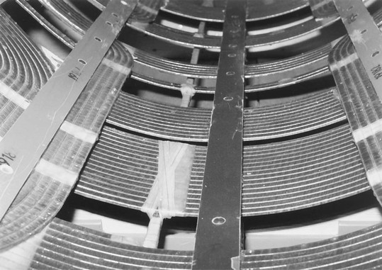
These bands are referred to as conductors and typically measure 10 mm wide and 4 mm thick. The large size is necessary to reduce resistance and carry the intense electric current (up to 30 A) required to generate the gradient magnetic fields (up to 40 mT/m). Gradient magnetic fields are measured in millitesla per meter, and when fast imaging is required, bigger is better.
These coils must be able to switch on and off rapidly. Switching times of less than 500 µs are necessary for many MRI applications. Advanced gradient coils, such as those used for echo planar imaging, can produce gradient fields of up to 40 mT/m, with switching times of as little as 50 µs.
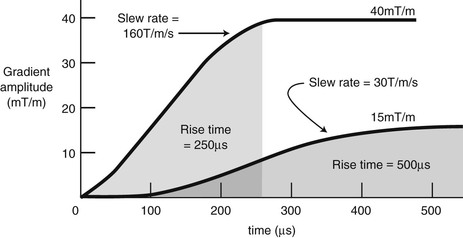
 The maximum rate of rise to maximum gradient amplitude is the slew rate. The time required to switch gradient coils from 10% to 90% of the maximum rated gradient strength is known as the rise time.
A typical slew rate curve is shown in Figure 11-4. This representation shows that the maximum gradient field, 40 mT/m, is obtained in a rise time of 250 µs. Therefore the slew rate is 160 T/m/s.


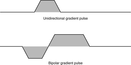
Because the current in the gradient coils cannot be brought to the required amplitude instantaneously, the waveforms used are generally trapezoidal, as shown in Figure 11-5.
For routine SE imaging, slew rate is important because it limits the minimum time-to-echo (TE) that is available. For fast imaging, slew rate is exceptionally important because it is the limiting specification for short repetition time (TR), short TE, and total imaging time.
The switching of the gradient coils produces the “thump, thump, thump” in the imaging aperture that is heard by the patient. When a gradient pulse begins, the electric charges accelerate in the gradient coil. Accelerating electric charges in a magnetic field will experience a force that is at right angles to both the direction of current flow and the magnetic field. When the gradient is switched off, the conductor will experience a force in the opposite direction. The alternate pushing and pulling on the conductors of the gradient coils produces noises in the same way that loudspeakers make sounds.
At low gradient pulsing rates a thumping sound is produced, but at the higher gradient pulsing rates used for MRI a nearly pure tone can be produced. These sounds are of adequate quality that a few demented researchers have been inspired to develop musical arrangements that can be played on MRI scanners.
Related posts:


Stay updated, free articles. Join our Telegram channel

Full access? Get Clinical Tree


