Magnetic Resonance Imaging Hardware
Objectives
At the completion of this chapter, the student should be able to do the following:
Key Terms
The basic physics of magnetic resonance imaging (MRI) have been covered in the previous chapters, and the equipment used in the process is discussed in this and the following two chapters.
An MRI system contains three major components, each of which is usually in a separate room and consists of several subsystems. The major components are the gantry, the operating console, and the system electronics cabinets. With the covers on, an MRI system resembles a computed tomography (CT) imaging or a positron emission tomography (PET) system. However, when you take the covers off, most of the similarities end. The principal components of an MRI system are shown in a block diagram in Figure 9-1.
 Magnet, operating console, and system electronics are the three principal components of an MRI system.
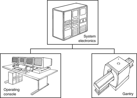
The gantry contains the main magnet and several other electromagnetic devices essential to producing MR images. With the exception of the table, there are no moving parts in the MRI gantry. The user interface of the operating console often resembles the manufacturer’s CT and nuclear medicine consoles, and although many of the control designations are similar, they also serve different functions.
The MRI system electronics include a powerful and fast signal acquisition computer, radio frequency amplifiers, gradient power supplies, frequency synthesizers, a pulse sequencing system, and digital image processing systems. The system electronics are often located in an adjacent, air conditioned room.
Each of the three types of MRI magnet systems—superconducting electromagnet, resistive electromagnet, and permanent magnet—uses similar computers, and the operating consoles have similar functional controls that appear the same. However, the gantries are completely different and each has a distinctive appearance. Because most MRI systems in use today are superconducting, the discussion in this chapter focuses more on that specific type.
The Gantry
The gantry can be intimidating, especially after the patient is placed on the examination couch and moved into the patient aperture. The patient then hears the resounding thump, thump, thump of the gradient coils, suggesting that this is indeed a big and intimidating machine. The MRI system is not a machine that has moving parts; rather it is an imaging system with no moving parts. However, the gantry does have many subsystems and several different electromagnetic coils.
Superconducting Magnetic Resonance Imaging System
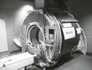
Figure 9-2 shows a typical superconducting MRI magnet in cross section. Superconducting MRI magnets are approximately 3 m across by 3 m high, with a length that ranges from 1.4 to 1.6 m. The massive size is due principally to the need to have the primary magnetic coils at a super-cooled temperature or cryogenic state. This cryogenic state is maintained by putting both the coils and the cryogens in insulating chambers.
 Cryogens are liquefied gases that produce supercold temperatures near absolute zero. Liquid helium is the cryogen that is used primarily to cool MRI magnet coils.
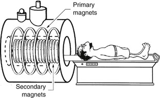
The gantry of a superconducting MRI system can be considered to have three subassemblies: the patient couch, the primary electromagnet assembly, and the various secondary electromagnets (Figure 9-3). The secondary electromagnets, used for generating the pulsed gradient and RF magnetic fields, are at room temperature, unlike the primary electromagnet, which is immersed in liquid helium.
The patient couch performs the two functions of support and position. The couch should, at a minimum, be able to accept patients who weigh up to 150 kg (~330 lb) at near floor level and raise the patient with a power assist to the level of the gantry patient aperture. From this position outside the gantry, the couch should be capable of moving to the imaging position under power assist to within ±1 mm.
Precise positioning is essential during examination. The imaging volume in superconducting magnets is approximately a 40 cm diameter sphere. In order to image extended sections of the body, such as a full spine, the couch must move in coordination with the scanning protocol to position the patient in the sweet spot, which is called the isocenter of the magnet.
This precision is obtained with specialty gears and electronic registers. Each revolution of the smallest drive gear corresponds to a 1 mm movement of the couch. Each revolution also activates an electronic counter so that the couch position can be visually displayed. Table 9-1 lists minimum acceptable specifications for the patient couch.
TABLE 9-1
Minimum Specifications for an MRI Patient-Positioning Couch
| Descriptor | Performance Standard |
| Patient capacity | 130 kg |
| Lift speed | 1 cm/s |
| Translation speed | 10 cm/s |
| Position accuracy | ±1 mm |
MRI, Magnetic resonance imaging.
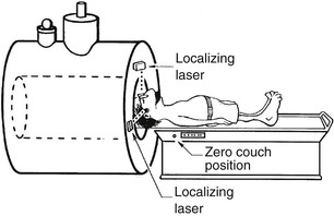
At installation, the service engineer adjusts the two or three positioning laser lights to intersect at a point on the axis of the MRI gantry (Figure 9-4). Usually, this position is then set at zero on the couch position indicator.
The primary electromagnet assembly is not visible. It is enclosed within a decorative plastic housing. Even with the housing removed, the primary electromagnet assembly cannot be seen because it is deep within the chambers of the cryostat. The innermost chamber of the cryostat houses an aluminum cylinder around which the superconducting wire is wound (Figure 9-5).
 The cryostat is a large insulating container in which liquid helium and the superconducting magnet coils reside.

Similarly, the secondary magnetic coils are not visible. They are also covered by a thick plastic liner inside the magnet bore. The relative position of these magnetic coils in the gantry is shown in Figure 9-6.
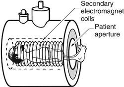
There are three sets of secondary magnetic coils, and they are independent. Nearest to the patient is the radiofrequency (RF) coil. The RF coil produces a magnetic field that oscillates at the resonant frequency of the hydrogen nucleus. The RF coil is designed to produce a magnetic field that is perpendicular to the primary magnetic field. This RF coil, often referred to as the “integrated body coil,” is a separate, removable assembly and therefore is not cryogenic but remains in place during all system operations and is kept at room temperature (Figure 9-7).
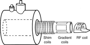
The secondary magnetic coils located closest to the patient aperture are the gradient coils, which are also at room temperature. These coils are large electrical conductors that produce the pulsed gradient magnetic fields. They are switched on and off rapidly. This current switching results in the conductor being subjected to a force, called the Lorentz force, that is at right angles to both the direction of current flow and the primary magnetic field, and this force causes the thumping sound that is commonly heard during scanning. This is the same prinicple under which loudspeakers operate, so we may think of the MRI system as a low-fidelity loudspeaker.
Between the gradient coils and the primary electromagnet assembly for earlier systems, shim coils were positioned to make the B0 field more homogeneous (uniform field intensity). Usually the shim coils were at room temperature, but in advanced MRI systems, they were in the cryostat.
Currently, shim coils are typically found only in MRI systems operating at 3 tesla or higher because of their expense and the desire to save the additional bore space that they occupy. In MRI systems at lower field strengths, long bars of ferromagnetic metals (called shim stock) are placed in trays along the inside of the magnet and used with gradient magnetic field offsets to obtain excellent B0 homogeneity.
Resistive Electromagnet Imaging System
The patient couch of a resistive electromagnet imaging system appears the same as that of a superconducting MRI system and will have similar performance characteristics. The coils are wound in four to six rings, each containing a coil of wire conducting a large electrical current, that ranges from 30 to 50 amperes (A) depending on the size of the magnet and B0 field strength required. The two large coils produce the B0 magnetic field, whereas the two smaller coils on each end help to extend the length of the field and make it uniform.
The secondary electromagnets of a resistive magnet imaging system are often wound in a flat plate that is put onto the pole caps of the magnet. This subassembly defines the patient aperture. Typically, the RF coil system is a separate operator-interchangeable assembly.
Resistive electromagnet MRI systems are rapidly disappearing from the scene. A few remaining 0.2-T and 0.5-T magnets may be resistive with an iron core. These magnets look like large C-arms and produce a vertical (floor-to-ceiling) B0 field.
Permanent Magnet Imaging System
The subassemblies of a permanent magnet imaging system are not visible because of a decorative housing. There is no hint of how the subassemblies appear except for the RF coils, which are identifiable and operator interchangeable.
The cutaway view of the permanent magnet MRI gantry in Figure 9-8
Related posts:

Stay updated, free articles. Join our Telegram channel

Full access? Get Clinical Tree


